Page 4669 of 5135

A85921
5mm
(0.20 in.)
A85914
SST
A8592215 mm (0.59 in.)
A87961
SST
14−128−
ENGINE MECHANICAL PARTIAL ENGINE ASSY (1CD −FTV)(From September,
2003)
AVENSIS Supplement (RM1045E)
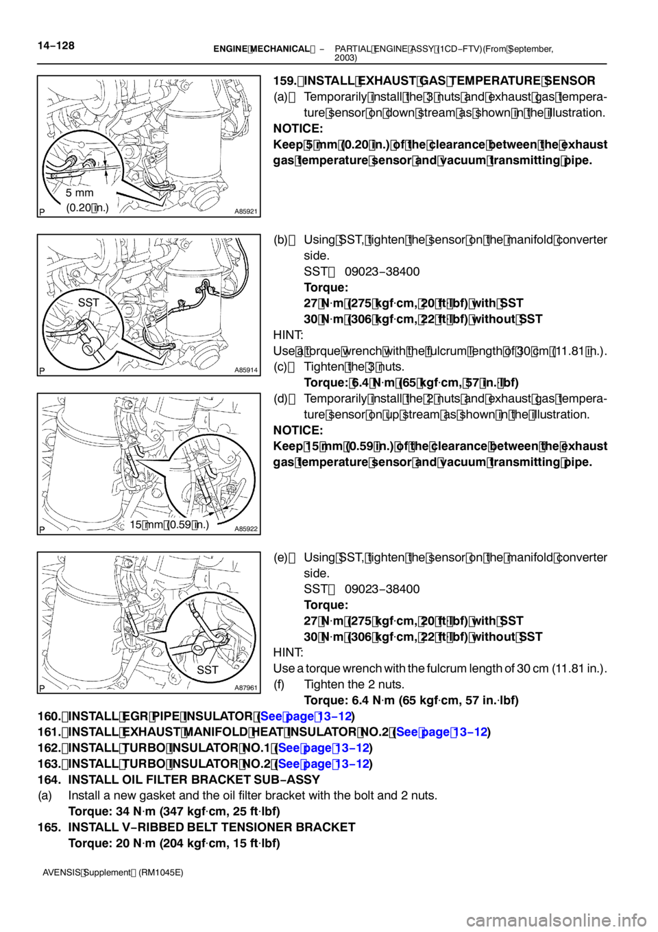
159. INSTALL EXHAUST GAS TEMPERATURE SENSOR
(a) Temporarily install the 3 nuts and exhaust gas tempera- ture sensor on down stream as shown in the illustration.
NOTICE:
Keep 5 mm (0.20 in.) of the clearance between the exhaust
gas temperature sensor and vacuum transmitting pipe.
(b) Using SST, tighten the sensor on the manifold converter
side.
SST 09023 −38400
Torque:
27 N �m (275 kgf �cm, 20 ft �lbf) with SST
30 N �m (306 kgf �cm, 22 ft �lbf) without SST
HINT:
Use a torque wrench with the fulcrum length of 30 cm (11.81 in.).
(c) Tighten the 3 nuts.
Torque: 6.4 N �m (65 kgf �cm, 57 in. �lbf)
(d) Temporarily install the 2 nuts and exhaust gas tempera- ture sensor on up stream as shown in the illustration.
NOTICE:
Keep 15 mm (0.59 in.) of the clearance between the exhaust
gas temperature sensor and vacuum transmitting pipe.
(e) Using SST, tighten the sensor on the manifold converter side.
SST 09023 −38400
Torque:
27 N �m (275 kgf �cm, 20 ft �lbf) with SST
30 N �m (306 kgf �cm, 22 ft �lbf) without SST
HINT:
Use a torque wrench with the fulcrum length of 30 cm (11.81 in.).
(f) Tighten the 2 nuts.
Torque: 6.4 N �m (65 kgf �cm, 57 in. �lbf)
160. INSTALL EGR PIPE INSULATOR (See page 13 −12)
161. INSTALL EXHAUST MANIFOLD HEAT INSULATOR NO.2 (See page 13 −12)
162. INSTALL TURBO INSULATOR NO.1 (See page 13 −12)
163. INSTALL TURBO INSULATOR NO.2 (See page 13 −12)
164. INSTALL OIL FILTER BRACKET SUB −ASSY
(a) Install a new gasket and the oil filter bracket with the bolt and 2 nuts.
Torque: 34 N �m (347 kgf �cm, 25 ft �lbf)
165. INSTALL V −RIBBED BELT TENSIONER BRACKET
Torque: 20 N �m (204 kgf �cm, 15 ft �lbf)
Page 4675 of 5135

A87967
Upward90_
Clamp
Bolt
Turbocharger Side:
Air Hose No. 2 Side:
Front 90
_ Clamp Bolt
20.4_
14
−134
−
ENGINE MECHANICAL PARTIAL ENGINE ASSY (1CD −FTV)(From September,
2003)
AVENSIS Supplement (RM1045E)
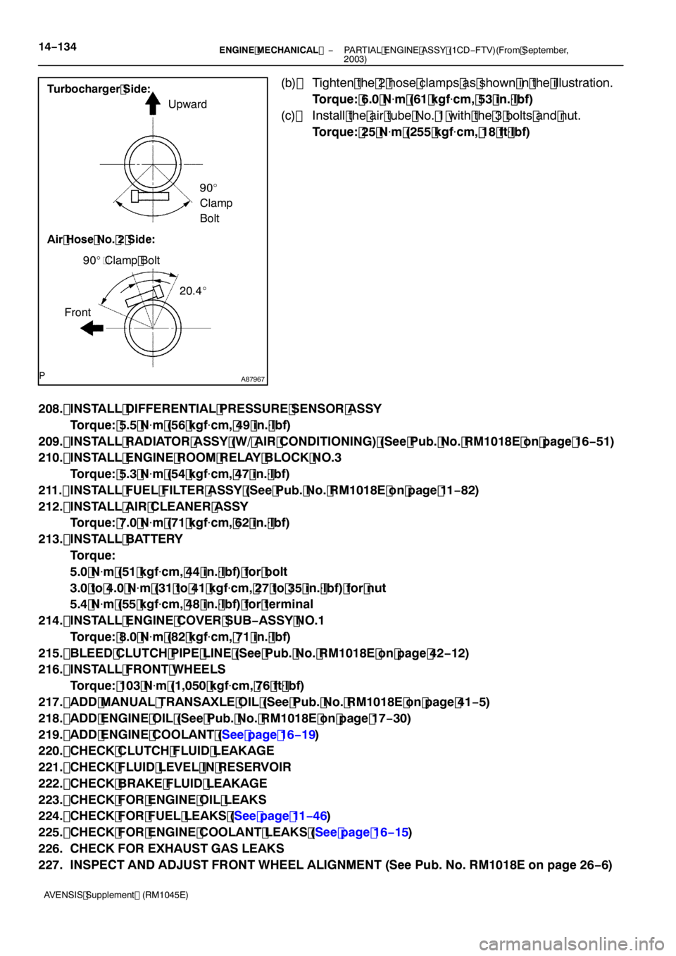
(b) Tighten the 2 hose clamps as shown in the illustration. Torque: 6.0 N �m (61 kgf �cm, 53 in. �lbf)
(c) Install the air tube No. 1 with the 3 bolts and nut. Torque: 25 N �m (255 kgf �cm, 18 ft �lbf)
208. INSTALL DIFFERENTIAL PRESSURE SENSOR ASSY Torque: 5.5 N �m (56 kgf �cm, 49 in. �lbf)
209. INSTALL RADIATOR ASSY (W/ AIR CONDITIONING) (See Pub. No. RM1018E on page 16 −51)
210. INSTALL ENGINE ROOM RELAY BLOCK NO.3
Torque: 5.3 N �m (54 kgf �cm, 47 in. �lbf)
211. INSTALL FUEL FILTER ASSY (See Pub. No. RM1018E on page 11 −82)
212. INSTALL AIR CLEANER ASSY Torque: 7.0 N �m (71 kgf �cm, 62 in. �lbf)
213. INSTALL BATTERY Torque:
5.0 N�m (51 kgf �cm, 44 in. �lbf) for bolt
3.0 to 4.0 N �m (31 to 41 kgf �cm, 27 to 35 in. �lbf) for nut
5.4 N �m (55 kgf �cm, 48 in. �lbf) for terminal
214. INSTALL ENGINE COVER SUB −ASSY NO.1
Torque: 8.0 N �m (82 kgf �cm, 71 in. �lbf)
215. BLEED CLUTCH PIPE LINE (See Pub. No. RM1018E on page 42 −12)
216. INSTALL FRONT WHEELS
Torque: 103 N �m (1,050 kgf �cm, 76 ft �lbf)
217. ADD MANUAL TRANSAXLE OIL (See Pub. No. RM1018E on page 41 −5)
218. ADD ENGINE OIL (See Pub. No. RM1018E on page 17 −30)
219. ADD ENGINE COOLANT (See page 16 −19)
220. CHECK CLUTCH FLUID LEAKAGE
221. CHECK FLUID LEVEL IN RESERVOIR
222. CHECK BRAKE FLUID LEAKAGE
223. CHECK FOR ENGINE OIL LEAKS
224. CHECK FOR FUEL LEAKS (See page 11 −46)
225. CHECK FOR ENGINE COOLANT LEAKS (See page 16 −15)
226. CHECK FOR EXHAUST GAS LEAKS
227. INSPECT AND ADJUST FRONT WHEEL ALIGNMENT (See Pub. No. RM1018E on page 26 −6)
Page 4685 of 5135

141ND−01
A57063
Measure Point for Belt
Deflection and Tension
Alternator
Crankshaft Compressor
P/SP/S
Alternator Crankshaft
A/C Equipped
A/C Not Equipped
−
ENGINE MECHANICAL ENGINE (1CD−FTV)(From September, 2003)
14 −87
AVENSIS Supplement (RM1045E)
ENGINE (1CD −FTV)(From September, 2003)
INSPECTION
1. INSPECT ENGINE COOLANT (See page 16 −15)
2. INSPECT ENGINE OIL (See page 17 −9)
3. INSPECT BATTERY (See Pub. No. RM1018E on page 19 −26)
4. INSPECT AIR CLEANER FILTER ELEMENT SUB −ASSY
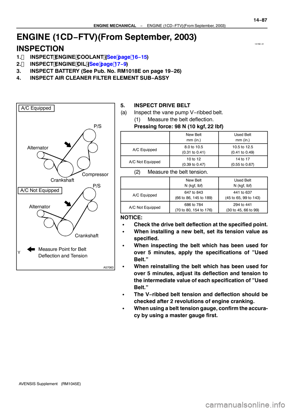
5. INSPECT DRIVE BELT
(a) Inspect the vane pump V −ribbed belt.
(1) Measure the belt deflection.
Pressing force: 98 N (10 kgf, 22 lbf)
New Belt
mm (in.)Used Belt mm (in.)
A/C Equipped8.0 to 10.5
(0.31 to 0.41)10.5 to 12.5
(0.41 to 0.49)
A/C Not Equipped10 to 12
(0.39 to 0.47)14 to 17
(0.55 to 0.67)
(2) Measure the belt tension.
New Belt
N (kgf, lbf)Used Belt
N (kgf, lbf)
A/C Equipped647 to 843
(66 to 86, 145 to 189)441 to 637
(45 to 65, 99 to 143)
A/C Not Equipped686 to 784
(70 to 80, 154 to 176)294 to 441
(30 to 45, 66 to 99)
NOTICE:
SCheck the drive belt deflection at the specified point.
SWhen installing a new belt, set its tension value as
specified.
SWhen inspecting the belt which has been used for
over 5 minutes, apply the specifications of ”Used
Belt.”
SWhen reinstalling the belt which has been used for
over 5 minutes, adjust its deflection and tension to
the intermediate value of each specification of ”Used
Belt.”
SThe V −ribbed belt tension and deflection should be
checked after 2 revolutions of engine cranking.
SWhen using a belt tension gauge, confirm the accura-
cy by using a master gauge first.
Page 5067 of 5135

A78516
A93669
14–10–
ENGINE MECHANICAL PARTIAL ENGINE ASSY (1ZZ–FE/3ZZ–FE)(From
February, 2004)
AVENSIS REPAIR MANUAL SUPPLEMENT
(RM1098E)
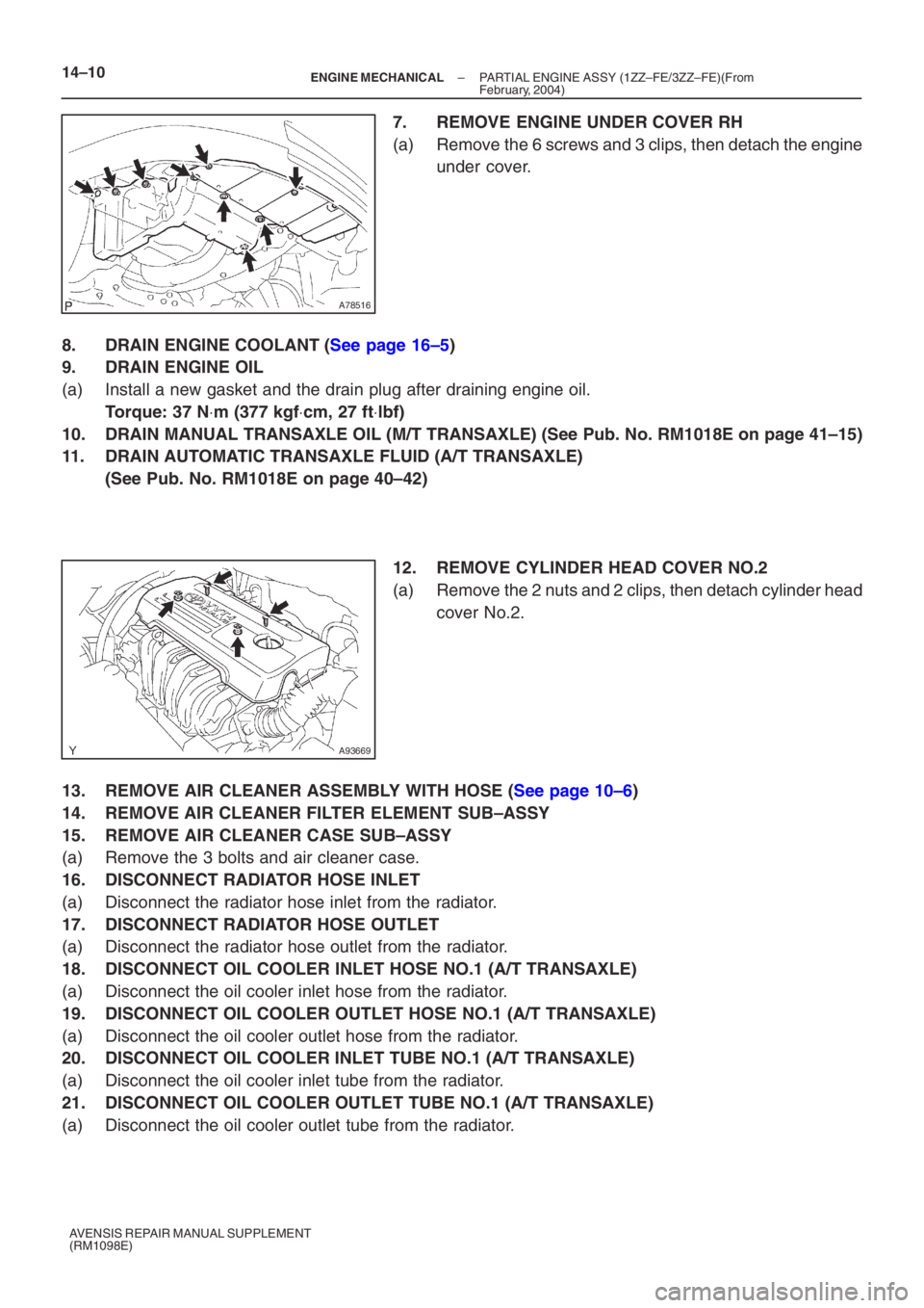
7. REMOVE ENGINE UNDER COVER RH
(a) Remove the 6 screws and 3 clips, then detach the engine under cover.
8. DRAIN ENGINE COOLANT (See page 16–5)
9. DRAIN ENGINE OIL
(a) Install a new gasket and the drain plug after draining engine oil.
Torque: 37 N ⋅m (377 kgf ⋅cm, 27 ft ⋅lbf)
10. DRAIN MANUAL TRANSAXLE OIL (M/T TRANSAXLE) (See Pub. No. RM1018E on p\
age 41–15)
11. DRAIN AUTOMATIC TRANSAXLE FLUID (A/T TRANSAXLE)
(See Pub. No. RM1018E on page 40–42)
12. REMOVE CYLINDER HEAD COVER NO.2
(a) Remove the 2 nuts and 2 clips, then detach cylinder head
cover No.2.
13. REMOVE AIR CLEANER ASSEMBLY WITH HOSE (See page 10–6)
14. REMOVE AIR CLEANER FILTER ELEMENT SUB–ASSY
15. REMOVE AIR CLEANER CASE SUB–ASSY
(a) Remove the 3 bolts and air cleaner case.
16. DISCONNECT RADIATOR HOSE INLET
(a) Disconnect the radiator hose inlet from the radiator.
17. DISCONNECT RADIATOR HOSE OUTLET
(a) Disconnect the radiator hose outlet from the radiator.
18. DISCONNECT OIL COOLER INLET HOSE NO.1 (A/T TRANSAXLE)
(a) Disconnect the oil cooler inlet hose from the radiator.
19. DISCONNECT OIL COOLER OUTLET HOSE NO.1 (A/T TRANSAXLE)
(a) Disconnect the oil cooler outlet hose from the radiator.
20. DISCONNECT OIL COOLER INLET TUBE NO.1 (A/T TRANSAXLE)
(a) Disconnect the oil cooler inlet tube from the radiator.
21. DISCONNECT OIL COOLER OUTLET TUBE NO.1 (A/T TRANSAXLE)
(a) Disconnect the oil cooler outlet tube from the radiator.