Page 275 of 5135
 ECM Connector
E13
EVP1 (+)
±
DIAGNOSTICS SFI SYSTEM(1ZZ±FE/3ZZ±FE)
05±95
AVENSIS REPAIR MANUAL (RM1018E)
1PERFORM ACTIVE TEST BY HAND±HELD TEST")
A79090VSV is ONVSV is OFF
E
F E
F
A18294
E01 (±) ECM Connector
E13
EVP1 (+)
±
DIAGNOSTICS SFI SYSTEM(1ZZ±FE/3ZZ±FE)
05±95
AVENSIS REPAIR MANUAL (RM1018E)
1PERFORM ACTIVE TEST BY HAND±HELD TESTER(VSV FOR EVAP)
(a)Select the ACTIVE TEST mode on the hand±held tester.
(b)Disconnect the vacuum hose from the VSV for EVAP.
(c)Start the engine.
(d)When the VSV for EVAP is operated by the hand±held
tester, apply the disconnected hose to your finger to
check the suction.
Result:
VSV is ON: Disconnected port sucks.
VSV is OFF: Disconnected port does not suck.
OKCHECK FOR INTERMITTENT PROBLEMS
NG
2INSPECT ECM(CHECK VOLTAGE)
(a)Turn the ignition switch ON.
(b)Measure the voltage between the terminals of the E13 ECM connector.
Standard:
Symbols (Terminal No.)Specified condition
EVP1 (E13±12) ± E01 (E13±7)8 to 14 V
OKCHECK AND REPLACE ECM
NG
3INSPECT VACUUM SWITCHING VALVE ASSY NO.1
NGREPLACE VACUUM SWITCHING VALVE ASSY NO.1
OK
4CHECK FUSE(EFI No.2) (See page 05±45)
NG CHECK FOR SHORT IN ALL HARNESS AND COMPONENTS CONNECTED FUSE
OK
Page 277 of 5135

A66053
Engine Room R/B No.4EFI Relay
�����
�
A79070
Engine Room R/B No.4EFI No.2 Fuse
1
2
��\b��A52933
Wire Harness Side
Vacuum Switching Valve Connector
V5
±
DIAGNOSTICS SFI SYSTEM(1ZZ±FE/3ZZ±FE)
05±97
AVENSIS REPAIR MANUAL (RM1018E)
6CHECK HARNESS AND CONNECTOR(EFI RELAY ± VSV FOR EVAP)
(a)Remove the EFI relay from the engine room R/B No.4.
(b)Remove the EFI No.2 fuse from the engine room R/B
No.4.
(c)Disconnect the VSV connector.
(d)Check for continuity between the wire harness side con- nectors.
Standard (Check for open):
Symbols (Terminal No.)Specified condition
EFI relay (3) ± EFI No.2 fuse (1)ContinuityEFI No.2 fuse (2) ± VSV (V5±1)Continuity
Standard (Check for short):
Symbols (Terminal No.)Specified condition
EFI relay (3) or EFI No.2 fuse (1) ± Body groundNocontinuityEFI No.2 fuse (2) or VSV (V5±1) ± Body groundNo continuity
NOTICE:
Do not insert the tester leads hard in the procedure (c), the
holder may be damaged.
NGREPAIR OR REPLACE HARNESS OR CONNECTOR
OK
CHECK FOR ECM POWER SOURCE CIRCUIT (See page 05±124)
Page 310 of 5135
A79100
I13
Ignition Switch
45
B±RB±Y
6
1
ST
2
6Fuse
Block
B±W
B±R B±R
1
1
IP1 IE4
(*1)
(*2)
B±R
1
2
1
1A 1AM2Engine
Room
R/B No.1
and
Engine
Room
J/B No.1
B±GB±Y
55
ST
Relay 51
32
55J13J12 BB
CA9
6N1
Neutral
Start
SwitchB±Y
(*4)
ECM
STA B±Y9
E12 B±W
(*3)
B±Y
(*3)
A J13 J12
J12
Junction
Connector
Engine
Room
J/B No.4 4A 1
1
4B
B±G
FL MAIN
BatteryB±R
IJDriver
Side R/B
BW±B
Driver
Side J/B DJ 2
DA 9
W±B B
S4
S511
Stater IK1
7*1: LHD
*2: RHD
*3: A/T
*4: M/T 05±136
± DIAGNOSTICSSFI SYSTEM (1ZZ±FE/3ZZ±FE)
AVENSIS REPAIR MANUAL (RM1018E)
WIRING DIAGRAM
Page 320 of 5135
A79096
Driver Side J/B
IGN Fuse
A66055
Engine Room R/B No.1
IG2 Fuse
B16200
± DIAGNOSTICSSFI SYSTEM (1ZZ±FE/3ZZ±FE)
05±127
AVENSIS REPAIR MANUAL (RM1018E)
4 CHECK FUSE(IGN FUSE)
(a) Remove the IGN fuse from the driver side J/B.
(b) Check for continuity in the IGN fuse.
Standard: Continuity
NG CHECK FOR SHORT IN ALL HARNESSES AND
COMPONENTS CONNECTED FUSE
OK
5 CHECK FUSE(IG2 FUSE)
(a) Remove the IG2 fuse from the engine room R/B No.1.
(b) Check for continuity in the IG2 fuse.
Standard: Continuity
NG CHECK FOR SHORT IN ALL HARNESSES AND
COMPONENTS CONNECTED FUSE
OK
6 INSPECT IG2 RELAY
(a) Remove the IG2 relay from the engine room R/B No.4.
(b) Inspect the IG2 relay.
Standard:
Terminal No.Specified condition
1 ± 2Continuity
No Continuity
3 ± 5Continuity
(Apply battery voltage Terminals 1 and 2)
NG REPLACE IG2 RELAY
OK
Page 321 of 5135
MREL (+)
A66054
Engine Room R/B No.1
EFI Fuse
05±128
± DIAGNOSTICSSFI SYSTEM (1ZZ±FE/3ZZ±FE)
AVENSIS REPAIR MANUAL (RM1018E)
7 INSPECT")
B50489Ignition Switch
I13
A18294ECM Connecter
E12E9
E1 (±)MREL (+)
A66054
Engine Room R/B No.1
EFI Fuse
05±128
± DIAGNOSTICSSFI SYSTEM (1ZZ±FE/3ZZ±FE)
AVENSIS REPAIR MANUAL (RM1018E)
7 INSPECT IGNITION OR STARTER SWITCH ASSY
(a) Measure the resistance between the connector terminals
shown in the chart below.
SwitchTerminal No.Resisitance
LOCKAll Terminals1M� or more
ACC1±31� or less
ON1±2, 1±3, 2±3, 5±61� or less
START4±5, 4±6, 5±6, 1±21� or less
NG REPLACE IGNITION OR STARTER SWITCH
ASSY
OK
CHECK AND REPAIR HARNESS AND CONNECTOR (BATTERY ± IGNITION SWITCH, IGNITION
SWITCH ± ECM)
8 INSPECT ECM(MREL VOLTAGE)
(a) Turn the ignition switch ON.
(b) Measure the voltage between the terminals of the E9 and
E12 ECM connector.
Standard:
Symbols (Terminal No.)Specified condition
MREL (E9±8) ± E1 (E12±7)9 to 14 V
NG CHECK AND REPLACE ECM
OK
9 CHECK FUSE(EFI FUSE)
(a) Remove the EFI fuse from the engine room R/B No.1.
(b) Check for continuity in the EFI fuse.
Standard: Continuity
NG CHECK FOR SHORT IN ALL HARNESSES AND
COMPONENTS CONNECTED FUSE
OK
Page 322 of 5135
������
�
A79065
Engine Room R/B No.4
EFI No.1 Fuse
B16200
± DIAGNOSTICSSFI SYSTEM (1ZZ±FE/3ZZ±FE)
05±129
AVENSIS REPAIR MANUAL (RM1018E)
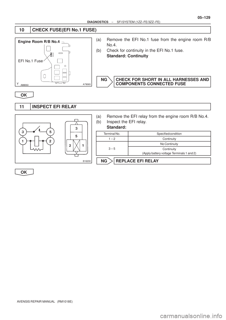
10 CHECK FUSE(EFI No.1 FUSE)
(a) Remove the EFI No.1 fuse from the engine room R/B
No.4.
(b) Check for continuity in the EFI No.1 fuse.
Standard: Continuity
NG CHECK FOR SHORT IN ALL HARNESSES AND
COMPONENTS CONNECTED FUSE
OK
11 INSPECT EFI RELAY
(a) Remove the EFI relay from the engine room R/B No.4.
(b) Inspect the EFI relay.
Standard:
Terminal No.Specified condition
1 ± 2Continuity
No Continuity
3 ± 5Continuity
(Apply battery voltage Terminals 1 and 2)
NG REPLACE EFI RELAY
OK
Page 323 of 5135

AVENSIS REPAIR MANUAL")
A66053
Engine Room R/B No.4
EFI Relay
������
�
A79066
Engine Room R/B No.4
EFI No.1 Fuse
1
2
A65748
MREL
E9
ECM Connector
+B
05±130
± DIAGNOSTICSSFI SYSTEM (1ZZ±FE/3ZZ±FE)
AVENSIS REPAIR MANUAL (RM1018E)
12 CHECK HARNESS AND CONNECTOR(EFI RELAY ± ECM, EFI RELAY ± BODY
GROUND)
(a) Check the harness and connector between the EFI relay
and ECM connector.
(1) Remove the EFI relay from the engine room R/B
No.4.
(2) Remove the EFI No.1 fuse from the engine room
R/B No.4.
(3) Disconnect the E9 ECM connector.
(4) Check for continuity between the wire harness side
connectors.
Standard (Check for open):
Symbols (Terminal No.)Specified condition
EFI relay (1) ± MREL (E9±8)
EFI relay (3) ± EFI No.1 fuse (1)Continuity
EFI No.1 fuse (2) ± +B (E9±1)
y
Standard (Check for short):
Symbols (Terminal No.)Specified condition
EFI relay (1) or MREL (E9±8) ± Body ground
EFI relay (3) or EFI No.1 fuse (1) ± Body groundNo continuity
EFI No.1 fuse (2) or +B (E9±1) ± Body ground
y
(b) Check the harness and connector between the EFI relay
and body ground.
(1) Remove the EFI relay from the engine room J/B
No.4.
(2) Check for continuity between the wire harness side
connector and the body ground.
Standard (Check for open):
Symbols (Terminal No.)Specified condition
EFI relay (2) ± Body groundContinuity
OK REPAIR OR REPLACE HARNESS OR
CONNECTOR
NG
CHECK AND REPAIR HARNESS AND CONNECTOR (TERMINAL +B OF ECM ± BATTERY POS-
ITIVE TERMINAL)
Page 324 of 5135
Heated Oxygen Sensor
EFI Relay
Heater
SensorOX1B HT1BECM
From
Battery EFI Fuse
O1B±
MREL
EFI No.2 Fuse
05±218
±
DIAGNOSTICS SFI SYSTEM(1AZ±")
���\b�A79115
Reference (Bank 1 Sensor 2 System Drawing)Heated Oxygen Sensor
EFI Relay
Heater
SensorOX1B HT1BECM
From
Battery EFI Fuse
O1B±
MREL
EFI No.2 Fuse
05±218
±
DIAGNOSTICS SFI SYSTEM(1AZ±FE)
AVENSIS REPAIR MANUAL (RM1018E)
DTCP0141/27OXYGEN SENSOR HEATER CIRCUIT MALFUNCTION (BANK 1 SENSOR 2)
DTCP0161/29OXYGEN SENSOR HEATER CIRCUIT (BANK 2 SENSOR 2)
CIRCUIT DESCRIPTION
Refer to DTC P0136/27 on page 05±211.
HINT:
The ECM provides a pulse width modulated control circuit to adjust current \
through the heater. The heated
oxygen sensor heater circuit uses a relay on the B+ side of the circuit.
DTC No.DTC Detection ConditionTrouble Area
P0141/27
Heated current is 0.2 A or less when heater operates
(1 trip detection logic)�Open or short in heater circuit of heated oxygen sensor
� Heated oxygen sensor heater
P0141/27
P0161/29When heater operates, heated current exceeds 2 A
(1 trip detection logic)
yg
�EFI relay
� ECM
HINT:
�Bank 1 refers to the bank that includes cylinder No.1.
�Bank 2 refers to the bank that does not include cylinder No.1.
�Sensor 1 refers to the sensor closest to the engine assembly.
�Sensor 2 refers to the sensor farthest away from the engine assembly.
WIRING DIAGRAM
Refer to DTC P0136/27 on page 05±211.
INSPECTION PROCEDURE
HINT:
�If different DTCs that are related to a different system are output simultaneously while terminal E2 is
used as a ground terminal, terminal E2 may be open.
�Read freeze frame data using �
\f
���
\f�� �\f��\f�� Freeze frame data records the engine conditions
when a malfunction is detected. When troubleshooting, it is useful for d\
etermining whether the vehicle
was running or stopped, the engine was warmed up or not, the air±fuel ra\
tio was lean or rich, etc. at
the time of the malfunction.
05C6Y±01

(*2)
B±R
1
2
1
1A 1AM2Engine
Room
R/B No.1
and
Engine
Room
J/B No.1
B±GB±Y
55
ST
Relay 51
32
55J13J12")

05±127
AVENSIS REPAIR MANUAL (RM1018E)
4 CHECK FUSE(IGN FUSE)
(a) Remove the I")