Page 430 of 5135

AVENSIS REPAIR MANUAL (RM1018E)
(a)Checking the DTCs using the hand±held tester. (1)Connect the hand±held tester to the DL")
A76859
Hand±Held Tester
DLC3
05±298
±
DIAGNOSTICS SFI SYSTEM(1AZ±FSE)
AVENSIS REPAIR MANUAL (RM1018E)
(a)Checking the DTCs using the hand±held tester. (1)Connect the hand±held tester to the DLC3.
(2)Turn the ignition switch ON and switch the hand±held tester main switch ON.
(3)Use the hand±held tester to check the DTCs and freeze frame data and note them down (for operat-
ing instructions, see the hand±held tester's instruc-
tion book).
(4)See page 05±309 to confirm the details of the DTCs.
HINT:
In the event that 2 or more DTCs are detected, the CHK ENG
lamp will indicate the smaller number DTC first.
(b) Clearing the DTCs using the hand±held tester. (1) Connect the hand±held tester to the DLC3.
(2) Turn the ignition switch ON.
(3) When operating the hand±held tester to erase thecodes, the DTCs and freeze frame data will be
erased. (See the hand±held tester's instruction
book for operating instructions.)
(c) Clearing the DTCs not using the hand±held tester. (1) Disconnect the battery terminal or remove the EFIand THROTTLE fuses from the engine room R/B
No. 1 for more than 60 seconds.
3. DTC CHECK (Check Mode)
HINT:
Hand±held tester only:
Compared to the normal mode, the check mode has more sens-
ing ability to detect malfunctions.
Furthermore, the same diagnostic items which are detected in
the normal mode can also be detected in the check (test) mode.
(a) Procedure for check mode using the hand±held tester.
(1) Check the initial conditions
�Battery positive voltage 11 V or more.
�Throttle valve fully closed.
�Transmission in the ºPº or ºNº position.
�Air conditioning switched OFF.
(2) Turn the ignition switch OFF.
(3) Connect the hand±held tester to the DLC3.
(4) Turn the ignition switch ON and switch the hand±
held tester main switch ON.
Page 431 of 5135

05±299
AVENSIS REPAIR MANUAL (RM1018E)
(5) Switch the hand±held tester from the normal mode
to the check (test) mode. The CHK E")
A76900
ON
OFF
0.13 sec.0.13 sec.
± DIAGNOSTICSSFI SYSTEM (1AZ±FSE)
05±299
AVENSIS REPAIR MANUAL (RM1018E)
(5) Switch the hand±held tester from the normal mode
to the check (test) mode. The CHK ENG blinks in
0.13 sec. intervals as shown in the illustration.
NOTICE:
If the hand±held tester switches the ECM from the normal
mode to the check mode or vice±versa, or if the ignition
switch is turned from ON to ACC or OFF during the check
mode, the DTC and freeze frame data will be erased.
(6) Start the engine. (The CHK ENG goes off after the
engine start.)
(7) Simulate the conditions of the malfunction de-
scribed by the customer.
NOTICE:
Leave the ignition switch ON until you have checked the
DTC, etc.
(8) After simulating the malfunction conditions, use the
hand±held tester diagnosis selector to check the
DTCs and freeze frame data, etc.
HINT:
Be sure not to turn the ignition switch OFF, because the diagno-
sis system is changed from the check mode to the normal mode
and will result in all of the DTCs and freeze frame data being
erased.
(9) After checking the DTC, inspect the applicable cir-
cuit.
(b) Clearing the DTCs using the hand±held tester.
(1) Connect the hand±held tester to the DLC3.
(2) Turn the ignition switch ON.
(3) When operating the hand±held tester to erase the
codes, the DTCs and freeze frame data will be
erased. (See the hand±held tester's instruction
book for operating instructions.)
(c) Clearing the DTCs not using the hand±held tester.
(1) Disconnect the battery terminal or remove the EFI
and THROTTLE fuses from the engine room R/B
No. 1 for more than 60 seconds.
Page 453 of 5135
A76870
ECM
STA
E129
B±Y
IJW±BJ12
B B J13
J/C W±B 1 5
32 1AM2 2
B±G
B±R1
S51S4
Starter
Battery7
IK1
FL MAIN 4B 4A
Engine Room
J/B No. 4
BB 55
55 1
11A
B±GB±R
IE41
(LHD)IP11
(RHD)B±R
Engine
Room
R/B No. 1
Engine
Room
J/B No.1
Driver
Side R/BST
Relay
2DJ
9DA Driver
Side J/B B±R
B±RI13
Ignition Switch
45B±Y
B±Y
6
2ST 1
6 Fuse
Block
B±WB±YB±Y B±Y
J12 A C J13
A
J12 1
1
(M/T)
B±W
(A/T)
N1
Neutral Start SW96B±Y
(A/T) 05±278
± DIAGNOSTICSSFI SYSTEM (1AZ±FE)
AVENSIS REPAIR MANUAL (RM1018E)
STARTER SIGNAL CIRCUIT
CIRCUIT DESCRIPTION
When the engine is cranked, the intake air flow becomes slow, so fuel vaporization is poor. A rich mixture
is therefore necessary in order to achieve good startability. While the engine is being cranked, the battery
voltage is applied to terminal STA of the ECM. The starter signal is mainly used to increase the fuel injection
volume for the starting injection control and after±start injection control.
WIRING DIAGRAM
05C7B±01
Page 459 of 5135

AVENSIS REPAIR MANUAL (RM1018E)
INSPECTION PROCEDURE
1INSPECT ECM(#1, #2, #3 OR")
A18294
#4#3#2#1E01
ECM Connector
E13
B16200
A79096
Driver Side J/BIGN Fuse
05±274
±
DIAGNOSTICS SFI SYSTEM(1AZ±FE)
AVENSIS REPAIR MANUAL (RM1018E)
INSPECTION PROCEDURE
1INSPECT ECM(#1, #2, #3 OR #4 VOLTAGE)
(a)Turn the ignition switch ON.
(b)Measure the voltage between the terminals of the E13 ECM connector.
Standard:
Symbols (Terminal No.)Specified condition
#1 (E13±1) ± E01 (E13±7)
#2 (E13±2) ± E01 (E13±7)9to14V#3 (E13±3) ± E01 (E13±7)9 to 14 V
#4 (E13±4) ± E01 (E13±7)
OKGo to step 7
NG
2INSPECT FUEL INJECTOR ASSY(CHECK RESISTANCE) (See page 11±22)
NG REPLACE FUEL INJECTOR ASSY
OK
3 INSPECT IG2 RELAY
(a) Remove the IG2 relay from the engine room R/B No.4.
(b) Inspect the IG2 relay. Standard:
Terminal No.Specified condition
1 ± 2Continuity
No Continuity
3 ± 5Continuity
(Apply battery voltage Terminals 1 and 2)
NG REPLACE IG2 RELAY
OK
4 CHECK FUSE(IGN FUSE)
(a) Remove the IGN fuse from the driver side J/B.
(b) Check for continuity in the IGN fuse. Standard: Continuity
NG CHECK FOR SHORT IN ALL HARNESS AND COMPONENTS CONNECTED FUSE
Page 461 of 5135
A66267
IG2 Wire Harness Side
Ignition Switch Connector
I13
A79103
Driver Side J/B
IGN Fuse12
������A79064
Engine Room R/B No.4
IG2 Relay
05±276
± DIAGNOSTICSSFI SYSTEM (1AZ±FE)
AVENSIS REPAIR MANUAL (RM1018E)
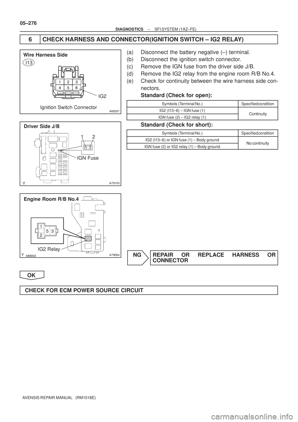
6 CHECK HARNESS AND CONNECTOR(IGNITION SWITCH ± IG2 RELAY)
(a) Disconnect the battery negative (±) terminal.
(b) Disconnect the ignition switch connector.
(c) Remove the IGN fuse from the driver side J/B.
(d) Remove the IG2 relay from the engine room R/B No.4.
(e) Check for continuity between the wire harness side con-
nectors.
Standard (Check for open):
Symbols (Terminal No.)Specified condition
IG2 (I13±6) ± IGN fuse (1)ContinuityIGN fuse (2) ± IG2 relay (1)Continuity
Standard (Check for short):
Symbols (Terminal No.)Specified condition
IG2 (I13±6) or IGN fuse (1) ± Body groundNo continuityIGN fuse (2) or IG2 relay (1) ± Body groundNo continuity
NG REPAIR OR REPLACE HARNESS OR
CONNECTOR
OK
CHECK FOR ECM POWER SOURCE CIRCUIT
Page 489 of 5135
A54396
+B
Wire Harness Side
Mass Air Flow Meter Connector
A6
A66053
Engine Room R/B No. 4
EFI Relay
±
DIAGNOSTICS SFI SYSTEM(1AZ±FSE)
05±341
AVENSIS REPAIR MANUAL (RM1018E)
7CHECK HARNESS AND CONNECTOR(EFI RELAY ± MASS AIR FLOW METER)
(a)Inspect the EFI No. 2 fuse.
(1)Remove the EFI No. 2 fuse from the engine room
R/B No. 4.
(2)Check for continuity in the EFI No. 2 fuse.
Standard: Continuity
(b)Disconnect the A6 mass air flow meter connector.
(c)Remove the EFI relay from the engine room R/B No. 4.
(d)Check for continuity between the wire harness side con- nectors.
Standard (Check for open):
Symbols (Terminal No.)Specified condition
+B (A6±1) ± EFI relay (3)Continuity
Standard (Check for short):
Symbols (Terminal No.)Specified condition
+B (A6±1) or EFI relay (3) ± Body groundNo continuity
NGREPAIR OR REPLACE HARNESS OR CONNECTOR
OK
CHECK FOR ECM POWER SOURCE CIRCUIT (See page 05±502)
Page 491 of 5135
Heated Oxygen Sensor
EFI Relay
Heater
SensorOX1A HT1A
Duty
Control
ECM
From
Battery EFI Fuse
E2
EFI No. 2
Fuse
MREL
OX HT
E1
+B
±
DIAGNOSTICS SFI S")
A72920
Reference (Bank 1 Sensor 1 System Drawing)Heated Oxygen Sensor
EFI Relay
Heater
SensorOX1A HT1A
Duty
Control
ECM
From
Battery EFI Fuse
E2
EFI No. 2
Fuse
MREL
OX HT
E1
+B
±
DIAGNOSTICS SFI SYSTEM(1AZ±FSE)
05±331
AVENSIS REPAIR MANUAL (RM1018E)
CIRCUIT DESCRIPTION
Refer to DTC P0130 on page 05±363.
HINT:
The ECM provides a pulse width modulated control circuit to adjust current \
through the heater. The heated
oxygen sensor heater circuit uses a relay on the B+ side of the circuit.
DTC No.DTC Detection ConditionTrouble Area
P0031
P0037Heated current is 0.2 A or less when heater operates with +B >
10.5 V and < 11.5 V (1 trip detection logic)�Open in heater circuit of heated oxygen sensor
� Heated oxygen sensor heater
� EFI relay
P0037
P0051
P0057Heated current is 0.25 A or less when heater operates with +B
� 11.5 V (1 trip detection logic)
EFI relay
�EFI fuse
� EFI No. 2 fuse
� ECM
P0032
P0038
P0052
P0058
Heated current exceeds 2 A when heater operates.
(1 trip detection logic)�Short in heater circuit of heated oxygen sensor
� Heated oxygen sensor heater
� ECM
HINT:
�Bank 1 refers to the No. 1 and No. 4 cylinders.
�Bank 2 refers to the No. 2 and No. 3 cylinders.
�Sensor 1 refers to the sensor closest to the engine assembly.
�Sensor 2 refers to the sensor farthest away from the engine assembly.
WIRING DIAGRAM
Refer to DTC P0130 on page 05±363.
INSPECTION PROCEDURE
HINT:
�If different DTCs related to different systems that have terminal E2 as the ground terminal are output
simultaneously, terminal E2 may be open.
�Read freeze frame data using the hand±held tester. Freeze frame data records the engine conditions
when a malfunction is detected. When troubleshooting, it is useful for deter\
mining whether the vehicle
was running or stopped, the engine was warmed up or not, the air±fuel ra\
tio was lean or rich, etc. at
the time of the malfunction.
Page 494 of 5135

A66290
Wire Harness Side
B1S1
B1S2
B2S1B2S2 H7
H9
H8
H10
Heated Oxygen Sensor Connector HT
HT
+B+B
A81695
HT1A
HT2BHT2A
HT1B
E12
ECM Connector
A66053
Engine Room R/B No. 4
EFI Relay
05±334
± DIAGNOSTICSSFI SYSTEM (1AZ±FSE)
AVENSIS REPAIR MANUAL (RM1018E)
4 CHECK HARNESS AND CONNECTOR(HEATED OXYGEN SENSOR ± ECM,
HEATED OXYGEN SENSOR ± EFI RELAY)
(a) Check the harness and connector between the ECM and
heated oxygen sensor connectors.
(1) Disconnect the H7, H8, H9 or H10 heated oxygen
sensor connector.
(2) Disconnect the E12 ECM connector.
(3) Check for continuity between the wire harness side
connectors.
Standard (Check for open):
Symbols (Terminal No.)Specified condition
HT (H7±1) ± HT1A (E12±5)
HT (H8±1) ± HT1B (E12±25)ContinuityHT (H9±1) ± HT2A (E12±4)Continuity
HT (H10±1) ± HT2B (E12±33)
Standard (Check for short):
Symbols (Terminal No.)Specified condition
HT (H7±1) or HT1A (E12±5) ± Body ground
HT (H8±1) or HT1B (E12±25) ± Body groundNo continuityHT (H9±1) or HT2A (E12±4) ± Body groundNo continuity
HT (H10±1) or HT2B (E12±33) ± Body ground
(b) Check the harness and connector between the heated
oxygen sensor connector and EFI relay.
(1) Inspect the EFI No.2 fuse.
�Remove the EFI No.2 fuse from the engine
room R/B No. 4.
�Check for continuity in the EFI No.2 fuse.
Standard: Continuity
(2) Disconnect the H7, H8, H9 or H10 heated oxygen
sensor connector.
(3) Remove the EFI relay from the engine room R/B No.
4.
(4) Check for continuity between the wire harness side
connectors.
Standard (Check for open):
Symbols (Terminal No.)Specified condition
+B (H7±2) ± EFI relay (3)
+B (H8±2) ± EFI relay (3)Continuity+B (H9±2) ± EFI relay (3)Continuity
+B (H10±2) ± EFI relay (3)
Standard (Check for short):
Symbols (Terminal No.)Specified condition
+B (H7±2) or EFI relay (3) ± Body ground
+B (H8±2) or EFI relay (3) ± Body groundNo continuity+B (H9±2) or EFI relay (3) ± Body groundNo continuity
+B (H10±2) or EFI relay (3) ± Body ground
IP11
(RHD)B±R
Engine
Ro")

05±341
AVENSIS REPAIR MANUAL (RM1018E)
7CHECK HARNESS AND CON")