Page 226 of 5135
05±58
±
DIAGNOSTICS SFI SYSTEM(1ZZ±FE/3ZZ±FE)
AVENSIS REPAIR MANUAL (RM1018E)
5CHECK FUSE(EFI No.2) (See page 05±45)
NGCHECK FOR SHORT IN ALL HARNESS AND COMPONENTS CONNECTED FUSE
OK
6CHECK HARNESS AND CONNECTOR(HEATED OXYGEN SENSOR ± ECM) (See page 05±45)
NGREPAIR OR REPLACE HARNESS OR CONNECTOR
OK
7CHECK HARNESS AND CONNECTOR(EFI RELAY ± HEATED OXYGEN SENSOR) (See page 05±45)
NGREPAIR OR REPLACE HARNESS OR
CONNECTOR
OK
8CHECK AIR INDUCTION SYSTEM
(a)Check for vacuum leaks in air induction system. NGREPAIR OR REPLACE AIR INDUCTION SYSTEM
OK
9CHECK FUEL PRESSURE (See page 11±5)
(a) Check the fuel pressure (high or low pressure). NG REPAIR OR REPLACE FUEL SYSTEM
OK
10INSPECT FUEL INJECTOR ASSY(INJECTION AND VOLUME) (See page 11±8)
NG REPLACE FUEL INJECTOR ASSY
OK
REPLACE HEATED OXYGEN SENSOR
11 PERFORM CONFIRMATION DRIVING PATTERN
GO
Page 232 of 5135
A79112
+BE2
Heated Oxygen Sensor
H7 HT
OX
A73938
+B
E2
Heated Oxygen Sensor
H17 HT
OX
������
� �
A79069
Engine Room R/B No.4 EFI No.2 Fuse
±
DIAGNOSTICS SFI SYSTEM(1ZZ±FE/3ZZ±FE)
05±49
AVENSIS REPAIR MANUAL (RM1018E)
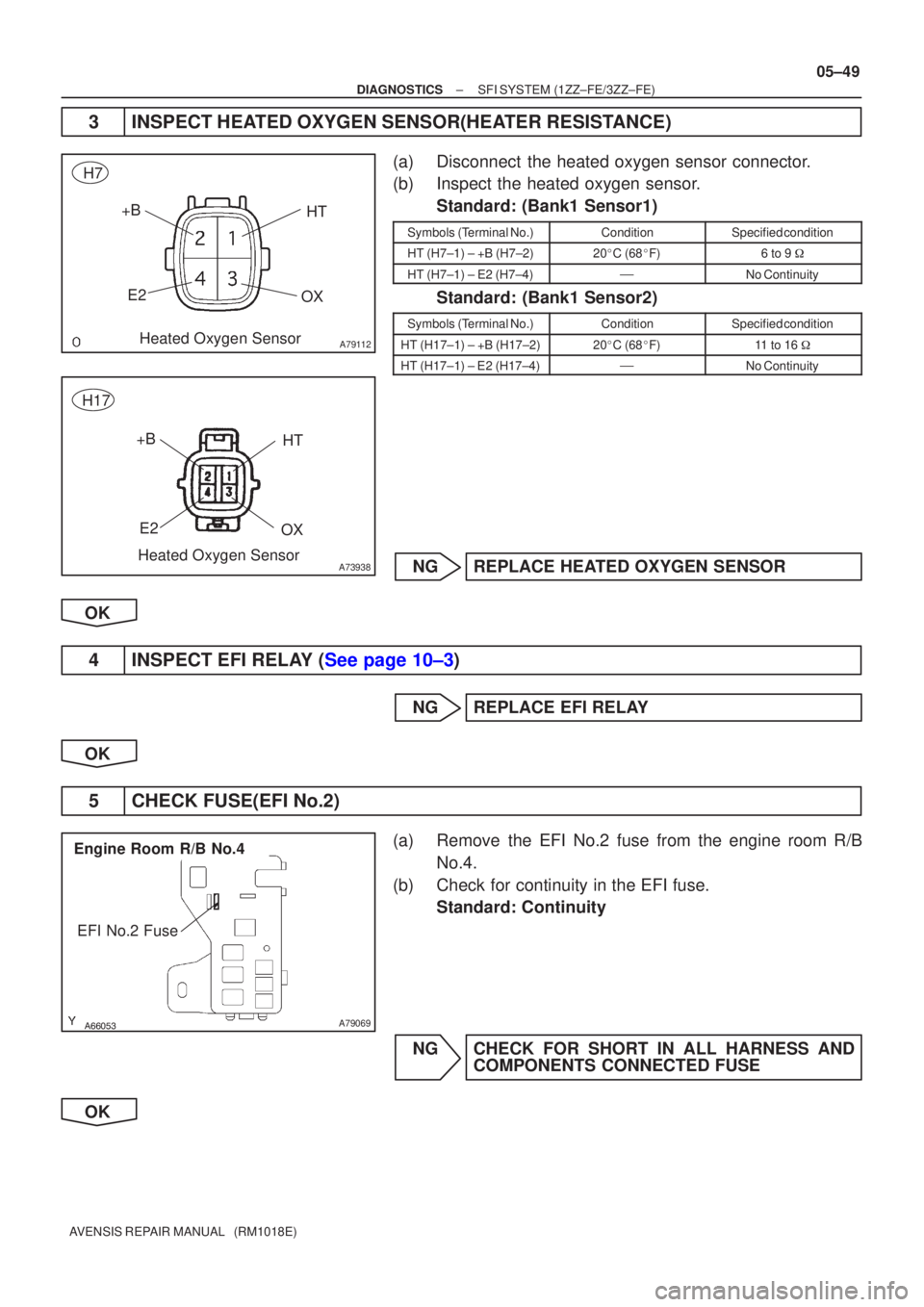
3INSPECT HEATED OXYGEN SENSOR(HEATER RESISTANCE)
(a)Disconnect the heated oxygen sensor connector.
(b)Inspect the heated oxygen sensor.
Standard: (Bank1 Sensor1)
Symbols (Terminal No.)ConditionSpecified condition
HT (H7±1) ± +B (H7±2)20�C (68 �F)6 to 9 �
HT (H7±1) ± E2 (H7±4)�No Continuity
Standard: (Bank1 Sensor2)
Symbols (Terminal No.)ConditionSpecified condition
HT (H17±1) ± +B (H17±2)20�C (68 �F)11 to 16 �
HT (H17±1) ± E2 (H17±4)�No Continuity
NGREPLACE HEATED OXYGEN SENSOR
OK
4INSPECT EFI RELAY (See page 10±3)
NG REPLACE EFI RELAY
OK
5 CHECK FUSE(EFI No.2)
(a) Remove the EFI No.2 fuse from the engine room R/B No.4.
(b) Check for continuity in the EFI fuse. Standard: Continuity
NG CHECK FOR SHORT IN ALL HARNESS AND COMPONENTS CONNECTED FUSE
OK
Page 234 of 5135

A66053
Engine Room R/B No.4
EFI Relay
������
�
A79070
Engine Room R/B No.4
EFI No.2 Fuse 1
2
A79114
OX+B
E2 HT
Heated Oxygen Sensor Connector Wire Harness Side
H7
OX+B
E2 HT
Heated Oxygen Sensor Connector Wire Harness Side
H17
A73939
± DIAGNOSTICSSFI SYSTEM (1ZZ±FE/3ZZ±FE)
05±51
AVENSIS REPAIR MANUAL (RM1018E)
7 CHECK HARNESS AND CONNECTOR(EFI RELAY ± HEATED OXYGEN SENSOR)
(a) Remove the EFI relay from the engine room R/BNo.4.
(b) Remove the EFI No.2 fuse from the engine room R/B
No.4.
(c) Disconnect the heated oxygen sensor connector.
(d) Check for continuity between the wire harness side con-
nectors.
Standard (Check for open):
Symbols (Terminal No.)Specified condition
EFI relay (3) ± EFI No.2 fuse (1)Continuity
Standard (Check for short):
Symbols (Terminal No.)Specified condition
EFI relay (3) or EFI No.2 fuse (1) ± Body groundNo continuity
Standard (Check for open): (Bank1 Sensor1)
Symbols (Terminal No.)Specified condition
EFI No.2 fuse (2) ± +B (H7±2)Continuity
Standard (Check for short): (Bank1 Sensor1)
Symbols (Terminal No.)Specified condition
EFI No.2 fuse (2) or +B (H7±2) ± Body groundNo continuity
Standard (Check for open): (Bank1 Sensor2)
Symbols (Terminal No.)Specified condition
EFI No.2 fuse (2) ± +B (H17±2)Continuity
Standard (Check for short): (Bank1 Sensor2)
Symbols (Terminal No.)Specified condition
EFI No.2 fuse (2) or +B (H17±2) ± Body groundNo continuity
NG REPAIR OR REPLACE HARNESS OR
CONNECTOR
OK
Page 252 of 5135
A66054
Engine Room R/B No.1EFI Fuse
A18294
BATT (+)E1 (±)
ECM Connector
E9E12
05±120
±
DIAGNOSTICS SFI SYSTEM(1ZZ±FE/3ZZ±FE)
AVENSIS REPAIR MANUAL (RM1018E)
1CHECK FUSE(EFI FUSE)
(a)Remove the EFI fuse from the engine room R/B No.1.
(b)Check for continuity in the EFI fuse. Standard: Continuity
NGCHECK FOR SHORT IN ALL HARNESSES AND COMPONENTS CONNECTED FUSE
OK
2INSPECT ECM(CHECK VOLTAGE)
(a)Turn the ignition switch ON.
(b)Measure the voltage between the terminals of the E9 and E12 ECM connector.
Standard:
Symbols (Terminal No.)Specified condition
BATT (E9±3) ± E1 (E12±7)8 to 14 V
OKCHECK AND REPLACE ECM (See page 01±32)
NG
Page 253 of 5135
A65748
E9
ECM Connector
BATT
������A79078
Engine Room R/B No.1
EFI Fuse
2
1
± DIAGNOSTICSSFI SYSTEM (1ZZ±FE/3ZZ±FE)
05±121
AVENSIS REPAIR MANUAL (RM1018E)
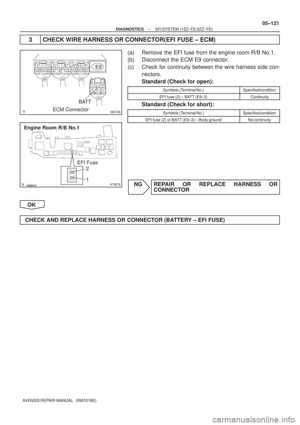
3 CHECK WIRE HARNESS OR CONNECTOR(EFI FUSE ± ECM)
(a) Remove the EFI fuse from the engine room R/B No.1.
(b) Disconnect the ECM E9 connector.
(c) Check for continuity between the wire harness side con-
nectors.
Standard (Check for open):
Symbols (Terminal No.)Specified condition
EFI fuse (2) ± BATT (E9±3)Continuity
Standard (Check for short):
Symbols (Terminal No.)Specified condition
EFI fuse (2) or BATT (E9±3) ± Body groundNo continuity
NG REPAIR OR REPLACE HARNESS OR
CONNECTOR
OK
CHECK AND REPLACE HARNESS OR CONNECTOR (BATTERY ± EFI FUSE)
Page 267 of 5135

05±109
AVENSIS REPAIR MANUAL (RM1018E")
A54393
+B
Ignition Coil and Igniter Connector
Wire Harness Side
I1
I2I3I4
������A79064IG2 Relay
Engine Room R/B No.4
±
DIAGNOSTICS SFI SYSTEM(1ZZ±FE/3ZZ±FE)
05±109
AVENSIS REPAIR MANUAL (RM1018E)
6CHECK HARNESS AND CONNECTOR(IG2 RELAY ± IGNITION COIL)
(a)Disconnect the ignition coil and igniter connector.
(b)Remove the IG2 relay from the engine room R/B No.4.
(c)Check for continuity between the wire harness side con-
nectors.
Standard (Check for open):
Symbols (Terminal No.)Specified condition
+B (I1±1) ± IG2 relay (3)
+B (I2±1) ± IG2 relay (3)Continuity+B (I3±1) ± IG2 relay (3)Continuity
+B (I4±1) ± IG2 relay (3)
Standard (Check for short):
Symbols (Terminal No.)Specified condition
+B (I1±1) or IG2 relay (3) ± Body ground
+B (I2±1) or IG2 relay (3) ± Body groundNocontinuity+B (I3±1) or IG2 relay (3) ± Body groundNo continuity
+B (I4±1) or IG2 relay (3) ± Body ground
NGREPLACE HARNESS OR CONNECTOR
OK
7CHECK FUSE(IGN FUSE) (See page 05±124)
NG CHECK FOR SHORT IN ALL HARNESSES AND COMPONENTS CONNECTED FUSE
OK
Page 268 of 5135
A66267
IG2 Wire Harness Side
Ignition Switch Connector
I13
A79103
Driver Side J/B
IGN Fuse12
������A79064
Engine Room R/B No.4
IG2 Relay
05±110
± DIAGNOSTICSSFI SYSTEM (1ZZ±FE/3ZZ±FE)
AVENSIS REPAIR MANUAL (RM1018E)
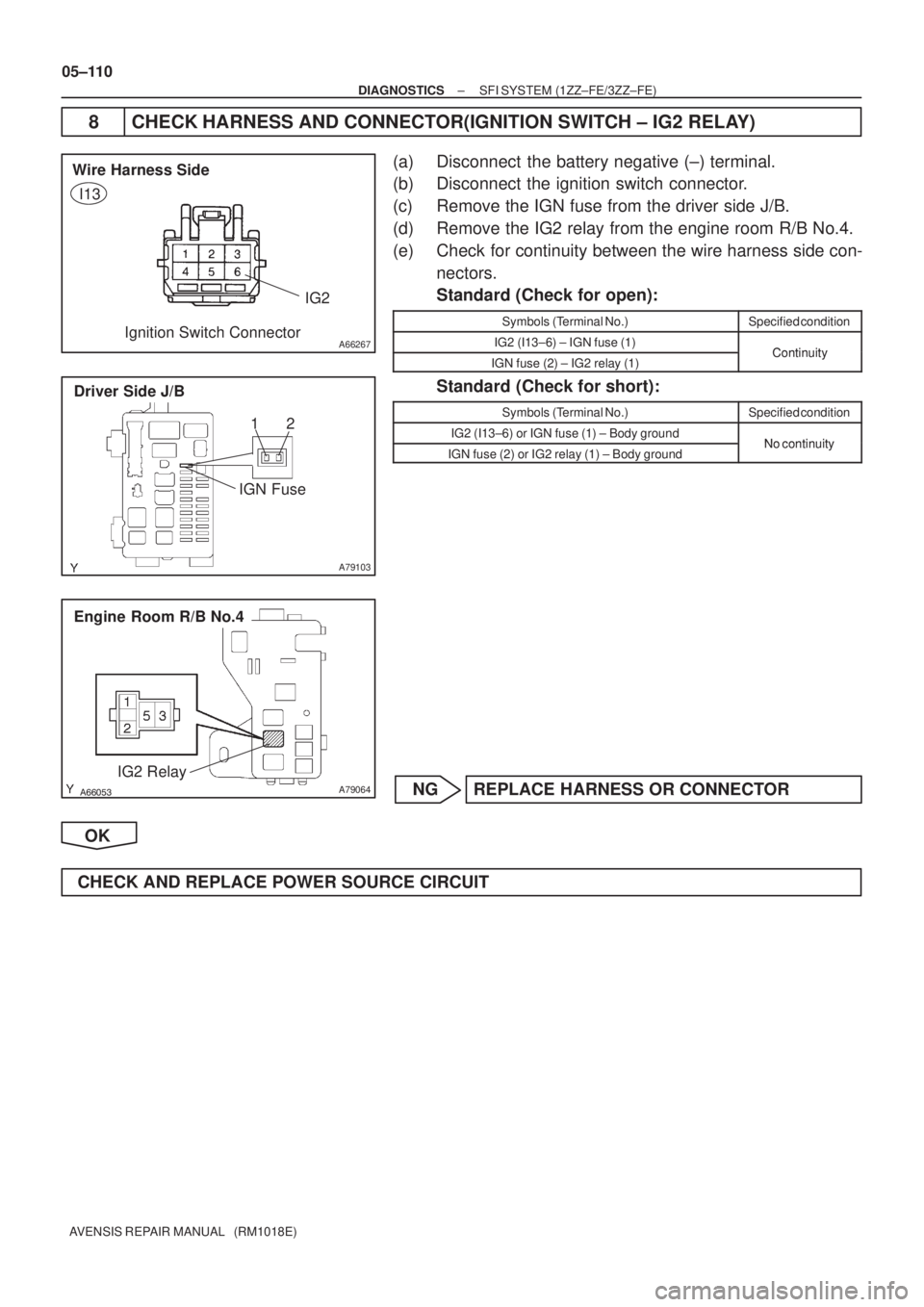
8 CHECK HARNESS AND CONNECTOR(IGNITION SWITCH ± IG2 RELAY)
(a) Disconnect the battery negative (±) terminal.
(b) Disconnect the ignition switch connector.
(c) Remove the IGN fuse from the driver side J/B.
(d) Remove the IG2 relay from the engine room R/B No.4.
(e) Check for continuity between the wire harness side con-
nectors.
Standard (Check for open):
Symbols (Terminal No.)Specified condition
IG2 (I13±6) ± IGN fuse (1)ContinuityIGN fuse (2) ± IG2 relay (1)Continuity
Standard (Check for short):
Symbols (Terminal No.)Specified condition
IG2 (I13±6) or IGN fuse (1) ± Body groundNo continuityIGN fuse (2) or IG2 relay (1) ± Body groundNo continuity
NG REPLACE HARNESS OR CONNECTOR
OK
CHECK AND REPLACE POWER SOURCE CIRCUIT
Page 269 of 5135

A79101
2 VISC DUTY1
GND 3
I10
ISC Valve
G±R5
E13 R")
A58697
Intake Air
Chamber
Throttle Valve
To Cylinder
ISC Valve
Valve
ECM
Signal From
Air
Cleaner
From
Terminal 2 of
EFI No.1 Fuse
(See Page 05±124)
A79101
2 VISC DUTY1
GND 3
I10
ISC Valve
G±R5
E13 RSDECM
B±R 12
EA1 B±R
W±B7
E13 E01
W±B
EG
05±100
±
DIAGNOSTICS SFI SYSTEM (1ZZ±FE/3ZZ±FE)
AVENSIS REPAIR MANUAL (RM1018E)
DTC P0505 IDLE CONTROL SYSTEM MALFUNCTION
CIRCUIT DESCRIPTION
The rotary solenoid type of the idle speed control (ISC) valve is
located under the throttle body and intake air bypassing the
throttle valve is directed to the ISC valve through the passage.
In this way the intake air volume bypassing the throttle valve is
regulated, controls the engine speed.
The ECM operates the ISC valve only to perform idle±up and
provide feedback for the target idling speed.
DTC No.DTC Detecting ConditionTrouble Area
P0505Idle speed continues to vary greatly from target speed
(1 trip detection logic)
� Open or short in ISC valve circuit
� ISC valve is stuck or closed
� PCV hose
� A/C switch circuit
� Air induction system
� ECM
WIRING DIAGRAM
INSPECTION PROCEDURE
HINT:
Read freeze frame data using \f�� �� ����\b� \f��\f�
� Freeze frame data records the engine conditions when
a malfunction is detected. When troubleshooting, it is useful for determi\
ning whether the vehicle was running
or stopped, the engine was warmed up or not, the air±fuel ratio was lea\
n or rich, etc. at the time of the mal-
function.
05B46±02

AVENSIS REPAIR MANUAL (RM1018E)
5CHECK FUSE(EFI No.2) (See page 05±45)
NGCHECK FOR SHORT IN ALL HARNESS AND COMPONENTS CONNECTED FUSE
OK
6CHECK HAR")
E1 (±)
ECM Connector
E9E12
05±120
±
DIAGNOSTICS SFI SYSTEM(1ZZ±FE/3ZZ±FE)
AVENSIS REPAIR MANUAL (RM1018E)
1CHECK FUSE(EFI FUSE)
(a)Remove the")