Page 326 of 5135
������
�
A79069
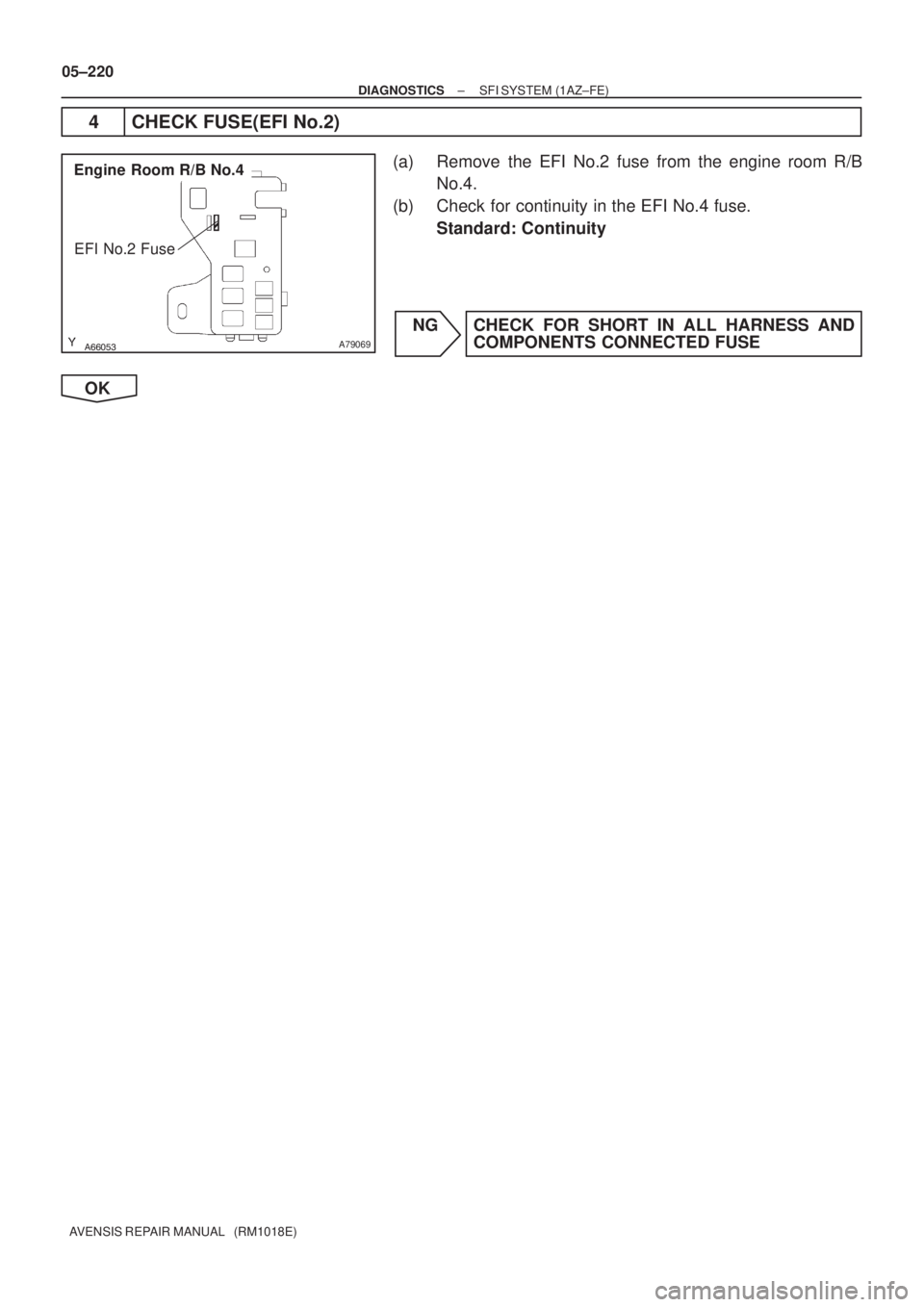
Engine Room R/B No.4
EFI No.2 Fuse
05±220
± DIAGNOSTICSSFI SYSTEM (1AZ±FE)
AVENSIS REPAIR MANUAL (RM1018E)
4 CHECK FUSE(EFI No.2)
(a) Remove the EFI No.2 fuse from the engine room R/B
No.4.
(b) Check for continuity in the EFI No.4 fuse.
Standard: Continuity
NG CHECK FOR SHORT IN ALL HARNESS AND
COMPONENTS CONNECTED FUSE
OK
Page 327 of 5135

A79118
Wire Harness SideBank 1
Sensor 2
Bank 2
Sensor 2 H8
H10
Heated Oxygen Sensor Connector +B
HT
A65744
HT2B
E10
ECM Connector
HT1B
������
� �
A79070
Engine Room R/B No.4
1 2
EFI No.2 Fuse
A66053
Engine Room R/B No.4
EFI Relay
±
DIAGNOSTICS SFI SYSTEM(1AZ±FE)
05±221
AVENSIS REPAIR MANUAL (RM1018E)
5CHECK HARNESS AND CONNECTOR(HEATED OXYGEN SENSOR ± ECM,
HEATED OXYGEN SENSOR ± EFI RELAY)
(a)Check the harness and connector between the ECM and
heated oxygen sensor connectors.
(1)Disconnect the H8 or H10 heated oxygen sensorconnector.
(2)Disconnect the E10 ECM connector.
(3)Check for continuity between the wire harness side connectors.
Standard (Check for open):
Symbols (Terminal No.)Specified condition
HT (H8±1) ± HT1B (E10±4)ContinuityHT (H10±1) ± HT2B (E10±3)Continuity
Standard (Check for short):
Symbols (Terminal No.)Specified condition
HT (H8±1)or HT1B (E10±4) ± Body groundNocontinuityHT (H10±1)or HT2B (E10±3) ± Body groundNo continuity
(b)Check the harness and connector between the heated oxygen sensor connector and EFI relay.
(1)Disconnect the H8 or H10 heated oxygen sensorconnector.
(2)Remove the EFI No.2 fuse from the engine room
R/B No.4.
(3)Remove the EFI relay from the engine room R/B No.4.
(4)Check for continuity between the wire harness side connectors.
Standard (Check for open):
Symbols (Terminal No.)Specified condition
+B (H8±2) ± EFI No.2 fuse (2)
+B (H10±2) ± EFI No.2 fuse (2)Continuity
EFI No.2 fuse (1) ± EFI relay (3)
y
Standard (Check for short):
Symbols (Terminal No.)Specified condition
+B (H8±2) or EFI No.2 fuse (2) ± Body ground
+B (H10±2) or EFI No.2 fuse (2) ± Body groundNo continuity
EFI No.2 fuse (1) or EFI relay (3) ± Body ground
y
NGREPAIR OR REPLACE HARNESS OR CONNECTOR
OK
CHECK AND REPLACE ECM (See page 01±32)
Page 333 of 5135

B16200
A79118
Wire Harness Side
Bank 1
Sensor 2
Bank 2
Sensor 2H8
H10
Heated Oxygen Sensor ConnectorOX
HT
A65747
HT1BHT2B
E12E10
ECM Connector
OX1BOX2B
������A79115
Heated Oxygen Sensor
EFI Relay
Heater
Sensor
OX1B HT1B
Duty
Control ECM
From
Battery
EFI Fuse
O1B±
MREL Reference (Bank 1 Sensor 2 System Drawing)
EFI No.2 Fuse 05±216
± DIAGNOSTICSSFI SYSTEM (1AZ±FE)
AVENSIS REPAIR MANUAL (RM1018E)
4 INSPECT EFI RELAY
(a) Remove the EFI relay from the engine room R/B No.4.
(b) Inspect the EFI relay.
Standard:
Terminal No.Specified condition
1 ± 2Continuity
No Continuity
3 ± 5Continuity
(Apply battery voltage Terminals 1 and 2)
NG REPLACE EFI RELAY
OK
5 CHECK HARNESS AND CONNECTOR(HEATED OXYGEN SENSOR ± ECM)
(a) Disconnect the H8 or H10 heated oxygen sensor connec-
tor.
(b) Disconnect the E10 and E12 ECM connector.
(c) Check for continuity between the wire harness side con-
nectors.
Standard (Check for open):
Symbols (Terminal No.)Specified condition
OX (H8±3) ± OX1B (E12±21)
HT (H8±1) ± HT1B (E10±4)ContinuityOX (H10±3) ± OX2B (E12±29)Continuity
HT (H10±1) ± HT2B (E10±3)
Standard (Check for short):
Symbols (Terminal No.)Specified condition
OX (H8±3) or OX1B (E12±21) ± Body ground
HT (H8±1) or HT1B (E10±4) ± Body groundNo continuityOX (H10±3) or OX2B (E12±29) ± Body groundNo continuity
HT (H10±1) or HT2B (E10±3) ± Body ground
Page 356 of 5135

A66053
Engine Room R/B No.4EFI Relay
������
�
A79066
Engine Room R/B No.4EFI No.1 Fuse
1
2
A54396Mass Air Flow Meter Connector
Wire Harness Side
+B
A6
A18294
EVG
ECM Connector E12
05±190
±
DIAGNOSTICS SFI SYSTEM(1AZ±FE)
AVENSIS REPAIR MANUAL (RM1018E)
5CHECK HARNESS AND CONNECTOR(MASS AIR FLOW METER ± EFI RELAY)
(a)Remove the EFI relay from the engine room R/B No.4.
(b)Remove the EFI No.1 fuse from the engine room R/B No.4.
(c)Disconnect the mass air flow meter connector.
(d)Check for continuity between the wire harness side con- nectors.
Standard (Check for open):
Symbols (Terminal No.)Specified condition
EFI relay (3) ± EFI No.1 fuse (1)ContinuityEFI No.1 fuse (2) ± +B (A6±1)Continuity
Standard (Check for short):
Symbols (Terminal No.)Specified condition
EFI relay (3) or EFI No.1 fuse (1) ± Body groundNocontinuityEFI No.1 fuse (2) or +B (A6±1) ± Body groundNo continuity
NOTICE:
Do not insert the tester leads hard in the procedure (c), the
holder may be damaged.
NGREPAIR OR REPLACE HARNESS OR CONNECTOR
OK
CHECK FOR ECM POWER SOURCE CIRCUIT (See page 05±257)
6 INSPECT ECM(SENSOR GROUND)
(a) Check for continuity between the terminal of the E12 ECM connector and the body ground.
Standard:
Symbols (Terminal No.)Specified condition
EVG (E12±32) ± Body groundContinuity
NG CHECK AND REPLACE ECM (See page 01±32)
OK
Page 359 of 5135

05±193
AVENSI")
A66053
Engine Room R/B No.4EFI Relay
������
�
A79066
Engine Room R/B No.4EFI No.1 Fuse
1
2
A54396Mass Air Flow Meter Connector
Wire Harness Side
+B
A6
±
DIAGNOSTICS SFI SYSTEM(1AZ±FE)
05±193
AVENSIS REPAIR MANUAL (RM1018E)
4CHECK HARNESS AND CONNECTOR(MASS AIR FLOW METER ± EFI RELAY)
(a)Remove the EFI relay from the engine room R/B No.4.
(b)Remove the EFI No.1 fuse from the engine room R/B
No.4.
(c)Disconnect the mass air flow meter connector.
(d)Check for continuity between the wire harness side con- nectors.
Standard (Check for open):
Symbols (Terminal No.)Specified condition
EFI relay (3) ± EFI No.1 fuse (1)ContinuityEFI No.1 fuse (2) ± +B (A6±1)Continuity
Standard (Check for short):
Symbols (Terminal No.)Specified condition
EFI relay (3) or EFI No.1 fuse (1) ± Body groundNocontinuityEFI No.1 fuse (2) or +B (A6±1) ± Body groundNo continuity
NOTICE:
Do not insert the tester leads hard in the procedure (c), the
holder may be damaged.
NGREPAIR OR REPLACE HARNESS OR CONNECTOR
OK
CHECK FOR ECM POWER SOURCE CIRCUIT (See page 05±257)
Page 360 of 5135
A/F Sensor
A/F Relay
Heater
Sensor A1A+ HA1A
Duty
Control
ECM
From
Battery A/F Fuse
A1A±
MREL
05±182
±
DIAGNOSTICS SFI SYSTEM(1AZ±FE)
AVENSIS REP")
B62793
Reference (Bank 1 Sensor 1 System Drawing)A/F Sensor
A/F Relay
Heater
Sensor A1A+ HA1A
Duty
Control
ECM
From
Battery A/F Fuse
A1A±
MREL
05±182
±
DIAGNOSTICS SFI SYSTEM(1AZ±FE)
AVENSIS REPAIR MANUAL (RM1018E)
DTCP0031/21OXYGEN (A/F) SENSOR HEATER CONTROL CIRCUIT LOW (BANK 1 SENSOR 1)
DTCP0032/21OXYGEN (A/F) SENSOR HEATER CONTROL CIRCUIT HIGH (BANK 1 SENSOR 1)
DTCP0051/28OXYGEN (A/F) SENSOR HEATER CONTROL CIRCUIT LOW (BANK 2 SENSOR 1)
DTCP0052/28OXYGEN (A/F) SENSOR HEATER CONTROL CIRCUIT HIGH (BANK 2 SENSOR 1)
CIRCUIT DESCRIPTION
Refer to DTC P2237/21 on page 05±248.
HINT:
�These DTCs are related to the air fuel raito (A/F) sensor, although the caption is the heated oxygen
sensor.
�The ECM provides a pulse width modulated control circuit to adjust curre\
nt through the heater. The
heated oxygen sensor heater circuit uses a relay on the B+ side of the c\
ircuit.
DTC No.DTC Detection ConditionTrouble Area
P0031/21
P0051/28Heated current is 0.8 A or less when heater operates
(1 trip detection logic)�Open or short in heater circuit of A/F sensor
� A/F sensor heater
P0032/21
P0052/28When the heater operates, heated current exceeds 19.7 A
(1 trip detection logic)�A/F relay
� ECM
HINT:
�Bank 1 refers to the bank that includes cylinder No.1.
�Bank 2 refers to the bank that does not include cylinder No.1.
�Sensor 1 refers to the sensor closest to the engine assembly.
�Sensor 2 refers to the sensor farthest away from the engine assembly.
05C6T±01
Page 378 of 5135
A76869
Engine Room R/B No.1
Engine Room J/B No.1
EFI
12
1 1A1
B±G
4A
4B 11
Engine
Room J/B No.4
B±G
FL MAIN
Battery
EFBR B±Y
IE3
IO1 77
(LHD)(RHD)B±Y3
E9 BATTECM
E1 7
E12
A66054
Engine Room R/B No.1
EFI Fuse
05±262
± DIAGNOSTICSSFI SYSTEM (1AZ±FE)
AVENSIS REPAIR MANUAL (RM1018E)
ECM BACK±UP POWER SOURCE CIRCUIT
CIRCUIT DESCRIPTION
While the ignition switch is OFF, the battery positive voltage is supplied to terminal BATT of the ECM for the
DTCs memory and air±fuel ratio adaptive control value memory, etc.
WIRING DIAGRAM
INSPECTION PROCEDURE
1 CHECK FUSE(EFI FUSE)
(a) Remove the EFI fuse from the engine room R/B No.1.
(b) Check for continuity in the EFI fuse.
Standard: Continuity
NG CHECK FOR SHORT IN ALL HARNESSES AND
COMPONENTS CONNECTED FUSE
OK
05C78±01
Page 379 of 5135
E1 (±)
ECM Connector
E9E12
A65748
E9
ECM Connector
BATT
������A79078
Engine Room R/B No.1 EFI Fuse2
1
±
DIAGNOSTICS SFI SYSTEM(1AZ±FE)
05±263
AVENSIS REPAIR MANUAL (RM1018E)
2INSP")
A18294
BATT (+)E1 (±)
ECM Connector
E9E12
A65748
E9
ECM Connector
BATT
������A79078
Engine Room R/B No.1 EFI Fuse2
1
±
DIAGNOSTICS SFI SYSTEM(1AZ±FE)
05±263
AVENSIS REPAIR MANUAL (RM1018E)
2INSPECT ECM(BATT VOLTAGE)
(a)Turn the ignition switch ON.
(b)Measure the voltage between the terminals of the E9 and
E12 ECM connector.
Standard:
Symbols (Terminal No.)Specified condition
BATT (E9±3) ± E1 (E12±7)8 to 14 V
OKCHECK AND REPLACE ECM (See page 01±32)
NG
3 CHECK HARNESS AND CONNECTOR(ECM ± EFI FUSE, EFI FUSE ± BATTERY)
(a) Check the harness and connector between the EFI fuse and ECM.
(1) Remove the EFI fuse from the engine room R/B.
(2) Disconnect the E9 ECM connector.
(3) Check for continuity between the wire harness sideconnectors.
Standard (Check for open):
Symbols (Terminal No.)Specified condition
EFI fuse (2) ± BATT (E9±3)Continuity
Standard (Check for short):
Symbols (Terminal No.)Specified condition
EFI fuse (2) or BATT (E9±3) ± Body groundNo continuity
(b) Check the harness and connector between the EFI fuse and battery.
(1) Remove the EFI fuse from the engine room R/B.
(2) Disconnect the battery positive terminal.
(3) Check for continuity between the wire harness sideconnectors.
Standard (Check for open):
Symbols (Terminal No.)Specified condition
Battery positive terminal ± EFI fuse (1)Continuity
Standard (Check for short):
Symbols (Terminal No.)Specified condition
Battery positive terminal or EFI fuse (1) ± Body groundNo continuity
NG REPAIR OR REPLACE HARNESS OR CONNECTOR
OK
CHECK AND REPLACE ENGINE ROOM RELAY BLOCK
(RHD)B±Y3
E9 BATTECM
E1 7
E12
A66054
Engine Room R/B N")