Page 592 of 5135

A79096
Driver Side J/B
IGN Fuse
A66267
Ignition Coil Connector
Wire Harness Side
IG2 I13
������A79064IG2 Relay
Engine Room R/B No. 4
������A81706
IG2 Fuse
Engine Room R/B No. 1
2
1
± DIAGNOSTICSSFI SYSTEM (1AZ±FSE)
05±511
AVENSIS REPAIR MANUAL (RM1018E)
7 CHECK HARNESS AND CONNECTOR(IGNITION SWITCH ± IG2 RELAY, IG2 FUSE
± IG2 RELAY)
(a) Check harness and connector between the IG2 relay and
ignition switch.
(1) Inspect the IGN fuse.
�Remove the IGN fuse from the driver side J/B.
�Check for continuity in the IGN fuse.
Standard: Continuity
�Reinstall the IGN fuse.
(2) Disconnect the I13 ignition switch connector.
(3) Remove the IG2 relay.
(4) Check for continuity between the wire harness side
connectors.
Standard (Check for open):
Symbols (Terminal No.)Specified condition
IG2 (I13±6) ± IG2 relay (1)Continuity
Standard (Check for short):
Symbols (Terminal No.)Specified condition
IG2 (I13±6) or IG2 relay (1) ± Body groundNo continuity
(b) Check harness and connector between the IG2 relay and
the IG2 fuse.
(1) Inspect the IG2 fuse.
�Remove the IG2 fuse from the engine room
R/B No. 1.
�Check for continuity in the IG2 fuse.
Standard: Continuity
(2) Remove the IG2 relay from the engine room R/B
No. 4.
(3) Check for continuity between the wire harness side
connectors.
Standard (Check for open):
Symbols (Terminal No.)Specified condition
IG2 fuse (2) ± IG2 relay (5)Continuity
Standard (Check for short):
Symbols (Terminal No.)Specified condition
IG2 fuse (2) or IG2 relay (5) ± Body groundNo continuity
NG REPAIR OR REPLACE HARNESS OR
CONNECTOR
OK
Page 596 of 5135
MREL (+)
05±504
±
DIAGNOSTICS SFI SYSTEM(1AZ±FSE)
AVENSIS REPAIR MANUAL (RM1018E)
4CHECK F")
A79096
Driver Side J/BIGN Fuse
B50489Ignition Switch
I13
Component Side
A67446ECM Connecter
E11E9
E1 (±)MREL (+)
05±504
±
DIAGNOSTICS SFI SYSTEM(1AZ±FSE)
AVENSIS REPAIR MANUAL (RM1018E)
4CHECK FUSE(IGN FUSE)
(a)Remove the IGN fuse from the driver side J/B.
(b)Check for continuity in the IGN fuse. Standard: Continuity
NGCHECK FOR SHORT IN ALL HARNESSES AND COMPONENTS CONNECTED FUSE
OK
5INSPECT IGNITION OR STARTER SWITCH ASSY
(a)Measure the resistance between the connector terminals shown in the chart below.
SwitchTerminal No.Resistance
LOCKAll Terminals1 M� or more
ACC1±31 � or less
ON1±2, 1±3, 2±3, 5±61 � or less
START4±5, 4±6, 5±6, 1±21 � or less
NGREPLACE IGNITION OR STARTER SWITCH
ASSY
OK
CHECK AND REPAIR HARNESS AND CONNECTOR(BATTERY ± IGNITION SWITCH, IGNITION
SWITCH ± ECM)
6INSPECT ECM(MREL VOLTAGE)
(a)Turn the ignition switch ON.
(b)Measure the voltage between the specified terminals of the E9 and E11 ECM connectors.
Standard:
Symbols (Terminal No.)Specified condition
MREL (E9±8) ± E1 (E11±1)9 to 14 V
NGCHECK AND REPLACE ECM (See page 01±32)
OK
Page 597 of 5135
A66054
Engine Room R/B No. 1
EFI Fuse
B16200
������
� �
A79065
Engine Room R/B No. 4
EFI No.1 Fuse
± DIAGNOSTICSSFI SYSTEM (1AZ±FSE)
05±505
AVENSIS REPAIR MANUAL (RM1018E)
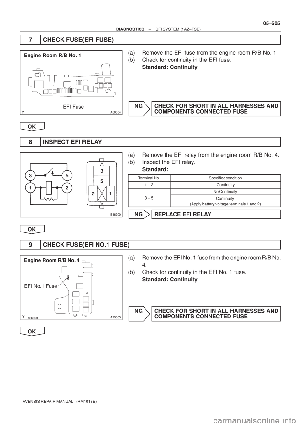
7 CHECK FUSE(EFI FUSE)
(a) Remove the EFI fuse from the engine room R/B No. 1.
(b) Check for continuity in the EFI fuse.
Standard: Continuity
NG CHECK FOR SHORT IN ALL HARNESSES AND
COMPONENTS CONNECTED FUSE
OK
8 INSPECT EFI RELAY
(a) Remove the EFI relay from the engine room R/B No. 4.
(b) Inspect the EFI relay.
Standard:
Terminal No.Specified condition
1 ± 2Continuity
No Continuity
3 ± 5Continuity
(Apply battery voltage terminals 1 and 2)
NG REPLACE EFI RELAY
OK
9 CHECK FUSE(EFI NO.1 FUSE)
(a) Remove the EFI No. 1 fuse from the engine room R/B No.
4.
(b) Check for continuity in the EFI No. 1 fuse.
Standard: Continuity
NG CHECK FOR SHORT IN ALL HARNESSES AND
COMPONENTS CONNECTED FUSE
OK
Page 598 of 5135

AVENSIS REPA")
A66053
Engine Room R/B No. 4
EFI Relay
������
�
A79066
Engine Room R/B No. 4
EFI No.1 Fuse
1
2
A67445
MREL
E9
ECM Connector+B
Wire Harness Side
05±506
± DIAGNOSTICSSFI SYSTEM (1AZ±FSE)
AVENSIS REPAIR MANUAL (RM1018E)
10 CHECK HARNESS AND CONNECTOR(EFI RELAY ± ECM, EFI RELAY ± BODY
GROUND)
(a) Check harness and connector between the EFI relay and
the ECM connector.
(1) Remove the EFI relay from the engine room R/B No.
4.
(2) Remove the EFI No.1 fuse from the engine room
R/B No. 4.
(3) Disconnect the E9 ECM connector.
(4) Check for continuity between the wire harness side
connectors.
Standard (Check for open):
Symbols (Terminal No.)Specified condition
EFI relay (1) ± MREL (E9±8)
EFI relay (3) ± EFI No. 1 fuse (1)Continuity
EFI No. 1 fuse (2) ± +B (E9±1)
y
Standard (Check for short):
Symbols (Terminal No.)Specified condition
EFI relay (1) or MREL (E9±8) ± Body ground
EFI relay (3) or EFI No. 1 fuse (1) ± Body groundNo continuity
EFI No. 1 fuse (2) or +B (E9±1) ± Body ground
y
(b) Check harness and connector between the EFI relay and
the body ground.
(1) Remove the EFI relay from the engine room R/B No.
4.
(2) Check for continuity between the wire harness side
connector and the body ground.
Standard (Check for open):
Symbols (Terminal No.)Specified condition
EFI relay (2) ± Body groundContinuity
OK REPAIR OR REPLACE HARNESS OR
CONNECTOR
NG
CHECK AND REPAIR HARNESS AND CONNECTOR(TERMINAL +B OF ECM ± BATTERY POSITIVE
TERMINAL)
Page 609 of 5135

E1 (±)
E10E11
ECM Connector
05±488
±
DIAGNOSTICS SFI SYSTEM(1AZ±FSE)
AVENSIS REPAIR MANUAL (RM1018E)
INSPECTION PROCEDURE
HINT:
Read fre")
A82233
THROTTLE Fuse
Engine Room R/B No. 1
A67446
+BM (+)
E1 (±)
E10E11
ECM Connector
05±488
±
DIAGNOSTICS SFI SYSTEM(1AZ±FSE)
AVENSIS REPAIR MANUAL (RM1018E)
INSPECTION PROCEDURE
HINT:
Read freeze frame data using the hand±held tester. Freeze frame data records the engine conditions when
a malfunction is detected. When troubleshooting, it is useful for determi\
ning whether the vehicle was running
or stopped, the engine was warmed up or not, the air±fuel ratio was lea\
n or rich, etc. at the time of the mal-
function.
1CHECK FUSE(THROTTLE FUSE)
(a)Remove the THROTTLE fuse from the engine room R/B No. 1.
(b)Check for continuity in the THROTTLE fuse. Standard: Continuity
NGCHECK FOR SHORT IN ALL HARNESSES AND COMPONENTS CONNECTED FUSE
OK
2INSPECT ECM(+BM VOLTAGE)
(a)Check the voltage between the specified terminals of the E10 and E11 ECM connectors.
Standard:
Symbols (Terminal No.)Specified condition
+BM (E10±6) ± E1 (E11±1)9 to 14 V
OKCHECK AND REPLACE ECM (See page 01±32)
NG
Page 610 of 5135

05±489
AVENSIS REPAIR MANUAL (RM1018E)
3 CHECK HARNESS AND CONNECTOR(ECM ± THROTTLE FUSE")
A82234
Engine Room R/B No. 1
THROTTLE Fuse
A67404
+BM
E10
ECM Connector
± DIAGNOSTICSSFI SYSTEM (1AZ±FSE)
05±489
AVENSIS REPAIR MANUAL (RM1018E)
3 CHECK HARNESS AND CONNECTOR(ECM ± THROTTLE FUSE, THROTTLE FUSE
± BATTERY)
(a) Check the harness and the connector between the
THROTTLE fuse and the ECM.
(1) Remove the THROTTLE fuse from the engine room
R/B No. 1.
(2) Disconnect the E10 ECM connector.
(3) Check for continuity between the wire harness side
connectors.
Standard (Check for open):
Symbols (Terminal No.)Specified condition
THROTTLE fuse (2) ± +BM (E10±6)Continuity
Standard (Check for short):
Symbols (Terminal No.)Specified condition
THROTTLE fuse (2) or +BM (E10±6) ± Body groundNo continuity
(b) Check the harness and the connector between the
THROTTLE fuse and the battery.
(1) Remove the THROTTLE fuse from the engine room
R/B No. 1.
(2) Disconnect the battery positive terminal.
(3) Check for continuity between the wire harness side
connectors.
Standard (Check for open):
Symbols (Terminal No.)Specified condition
Battery positive terminal ± THROTTLE fuse (1)Continuity
Standard (Check for short):
Symbols (Terminal No.)Specified condition
Battery positive terminal or THROTTLE fuse (1)
± Body groundNo continuity
NG REPAIR OR REPLACE HARNESS OR
CONNECTOR
OK
CHECK AND REPLACE ENGINE ROOM RELAY BLOCK
Page 615 of 5135

A81699SCV
E13ECM Connector
A56870
Wire Harness Side
VSV for IACV Connector
V6
A66053
Engine Room R/B No. 4EFI Relay
A56870
Wire Harness Side
VSV for IACV Connector
V6
05±482
±
DIAGNOSTICS SFI SYSTEM(1AZ±FSE)
AVENSIS REPAIR MANUAL (RM1018E)
4CHECK HARNESS AND CONNECTOR(ECM ± VSV FOR IACV)
(a)Disconnect the V6 VSV for IACV connector.
(b)Disconnect the E13 ECM connector.
(c)Check for continuity between the wire harness side con- nectors.
Standard (Check for open):
Symbols (Terminal No.)Specified condition
VSV for IACV (V6±2) ± SCV (E13±5)Continuity
Standard (Check for short):
Symbols (Terminal No.)Specified condition
VSV for IACV (V6±2) or SCV (E13±5) ± Body groundNo continuity
NGREPAIR OR REPLACE HARNESS OR CONNECTOR
OK
5CHECK HARNESS AND CONNECTOR(EFI RELAY ± VSV FOR IACV)
(a)Inspect the EFI No. 2 fuse. (1)Remove the EFI No. 2 fuse from the engine roomR/B No. 4.
(2)Check the continuity of the EFI No. 2 fuse.
Standard: Continuity
(b)Remove the EFI relay from the engine room R/B No. 4.
(c)Disconnect the V6 VSV for IACV connector.
(d)Check for continuity between the wire harness side con- nector.
Standard (Check for open):
Symbols (Terminal No.)Specified condition
VSV for IACV (V6±1) ± EFI relay (3)Continuity
Standard (Check for short):
Symbols (Terminal No.)Specified condition
VSV for IACV (V6±1) or EFI relay (3) ± Body groundNo continuity
NGREPAIR OR REPLACE HARNESS OR CONNECTOR
OK
CHECK FOR ECM POWER SOURCE CIRCUIT (See page 05±502)
Page 627 of 5135

AVENSIS REPAIR MANUAL (RM1018E) P0380
(05±622)
Glow Plug/Heater Circuit ºAº
� Open or short in glow plug circuit
� Glow fuse
� Glow relay
� Glow plug")
05±546
±
DIAGNOSTICS ECD SYSTEM (1CD±FTV)
AVENSIS REPAIR MANUAL (RM1018E) P0380
(05±622)
Glow Plug/Heater Circuit ºAº
� Open or short in glow plug circuit
� Glow fuse
� Glow relay
� Glow plug
� ECM
��
P0400
(05±629)Exhaust Gas Recirculation Flow� EGR valve assy
� EGR passage��
P0403
(05±629)Exhaust Gas Recirculation Con-
trol Circuit
EGR assage
� Open or short in EGR circuit
� ECM��
P0488
(05±633)Exhaust Gas Recirculation
Throttle Position Control Range/
Performance� Open or short in intake shutter circuit
� Open or short in fully opened switch circuit
� Intake shutter
� ECM
��
P0500
(05±640)Vehicle Speed Sensor ºAº
� Open or short in speed sensor circuit
� Speed sensor
� Combination meter
� ECM
� Skid control ECU
��
P0504
(05±643)Brake Switch ºAº/ºBº Correlation
� Short in stop lamp switch signal circuit
� Stop lamp switch
� ECM
��
P0560
(05±647)System Voltage� Open in back±up power source circuit
� ECM��
P0606
(05±650)ECM/PCM Processor
� ECM
��
P0607
(05±650)Control Module Performance
� ECM
��
P0622
(05±651)Generator Field ºFº Terminal Cir-
cuit
� Open in generator circuit
� Generator
� Drive belt
� ECM
��
P0627
(05±655)Fuel Pump Control Circuit / Open
� Open or shot in suction control valve circuit
� Suction control valve
� ECM
��
P1229
(05±563)Fuel Pump System
� Short in supply pump (suction control valve) circuit
� Suction control valve
� ECM
��
P1238
(05±658)Injector Malfunction
� Injector
� EDU (P0200 is set simultaneously)
� Open or short in engine wire (P0200 is set simultaneously)
� Connector connection (P0200 is set simultaneously)
� Compression pressure
� Valve clearance
� Valve timing
� ECM
��
P1251
(05±612)Turbo/Super Charger Overboost
Condition (Too High)
� VRV
� Open or short in VRV circuit
� Turbocharger
� EGR valve
� Vacuum hose
� ECM
��
P1271
(05±663)Fuel Regulator Circuit Malfunc-
tion (EDU Drive)
� Open or short in pressure discharge valve circuit
� Open or short in pressure discharge valve it self
� EDU
� ECM
��
P1272
(05±663)Fuel Pressure Regulator Mal-
function
� Open or short in pressure discharge valve circuit (P1271 is set
simultaneously)
� Pressure discharge valve
� Supply pump
� ECM
��