Page 1187 of 5135
I36137
+
P1
I37732
1 23 4
5 67 8
±P1
05±1172
±
DIAGNOSTICS COMBUSTION TYPE POWER HEATER SYSTEM
AVENSIS REPAIR MANUAL (RM1018E)
1CHECK FUSE(PWR HTR)
(a)Remove the PWR HTR from the engine room J/B or R/B No.1.
(b)Check that the continuity exists of PWR HTR fuse. NGREPAIR OR REPLACE FUSE
OK
2INSPECT POWER HEATER ECU(+)
(a)Remove the power heater ECU with connectors being connected.
(b)Turn the ignition switch to ON.
(c)Measure the voltage between terminal º+º of the power heater ECU and body ground.
Standard: 10 to 14 V
NGREPAIR OR REPLACE WIRE HARNESS
OK
3CHECK HARNESS AND CONNECTOR(POWER HEATER ECU ± BODY GROUND)
(a)Check for an open or short circuit in harness and connec- tor between the power heater ECU and body ground
(See page 01±32).
NG REPAIR OR REPLACE WIRE HARNESS
OK
PROCEED TO NEXT CIRCUIT INSPECTION SHOWN IN PROBLEM SYMPTOMS TABLE
Page 1190 of 5135
05C7X±01
I36096
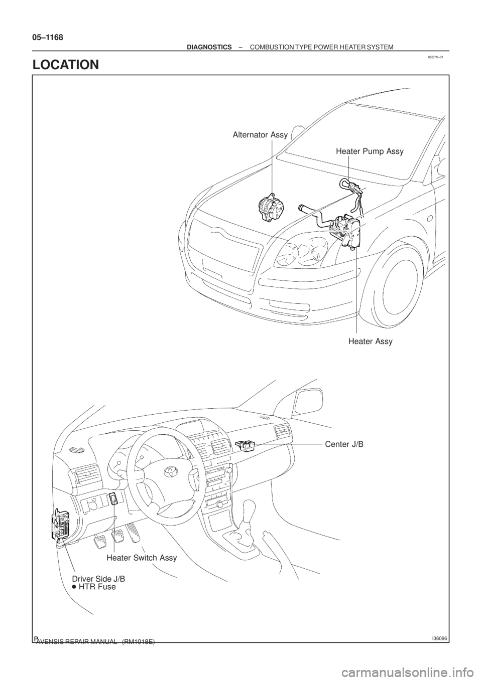
Heater Pump Assy Alternator Assy
Heater Assy
Center J/B
Heater Switch Assy
Driver Side J/B
� HTR Fuse
05±1168
± DIAGNOSTICSCOMBUSTION TYPE POWER HEATER SYSTEM
AVENSIS REPAIR MANUAL (RM1018E)
LOCATION
Page 1194 of 5135
I35431
Buner Motor
Glow Plug
Surface Sensor
Temp.Control Sensor
Flame Sensor13
Power
Heater
ECU
Connector BTerminal L
of AlternatorBattery
Metering Pump
Fuse (20 A)
Vehicle Side SW 14
9
12
5
6
3
4
1
2BR
G
L±Y
L B±R
Y
L±WR
1
2
3
4 5
6
7
8W±B Connector A
IG
R±G
R±L (*1)
R±Y (*2)
R±B
W±R (*1)
Y±R (*2)
*1: TMC Made
*2: TMUK Made
± DIAGNOSTICSCOMBUSTION TYPE POWER HEATER SYSTEM
05±1165
AVENSIS REPAIR MANUAL (RM1018E)
2. DESCRIPTION OF DISPLAY AND BUTTONS
(a) AF: Current Value Malfunction (Blinking at current failure)
Diag: DTC (Example: 064 Flame sensor break)
Memory Clear button: Deletion of faulty memory (Press both buttons together for longer than 2 sec.)
> Button: Scroll up of faulty memory (The past 5 codes can be stored.)
< Button: Scroll down of faulty memory (The past 5 codes can be stored.)
3. FAULTY MEMORY
(a) The ECU is able to store upto 5 pieces of faulty memory. If it is full, the new data is written over F5.
4. WIRING DIAGRAM
Page 1198 of 5135
I35396
R±W (*2) R±W (*2, *1) G±Y (*1)
W±B (*1)
W±B
(*1) R±W (*3, *1)
R±W (*3)
R±W (*2)CB1
CK 12 Center J/BP5
Power Heater SWA/C Control Assembly
A1611
J/C
J26H
J27F3IG
IN 6
E2
A
A J16
J/C
Driver Side J/B
DC6
From
HTR Fuse
ILHOTGASIN
*1: 1CD±FTV
*2: LHD
*3: RHD
± DIAGNOSTICSAIR CONDITIONING SYSTEM
05±1159
AVENSIS REPAIR MANUAL (RM1018E)
HOT GAS HEATER SWITCH CIRCUIT
CIRCUIT DESCRIPTION
Hot gas heater performs only when its switch turns to ON and fulfill the following 6 conditions.
�Hot gas heater switch is ON.
�Recirculation damper position is FRS.
�Blower motor switch is in the position other than OFF.
�Ambient temperature varies according to the following condition;
A/C switch ONBelow ±1.5�C (32�F)
A/C switch OFFBelow 8�C (46�F)
�Air mix damper position is MAX HOT.
�Water temperature is 70�C (158�F) or less.
WIRING DIAGRAM
05C7S±01
Page 1200 of 5135
I35380
R±W
(*2)J26 J26HH
IE111
IE218
A157
MGV A/C Control Assembly
R±W
(*2)R±W R±B R±Y J/CC4
Condenser
Assembly
12
Driver Side J/B
DC6
DB5
R±W
(*1)
From
HTR Fuse
*1: LHD
*2: RHD
± DIAGNOSTICSAIR CONDITIONING SYSTEM
05±1157
AVENSIS REPAIR MANUAL (RM1018E)
HOT GAS HEATER MAGNETIC VALVE CIRCUIT
CIRCUIT DESCRIPTION
For the hot gas heater, it is necessary to fulfill the following 6 conditions.
�Hot gas heater switch is ON.
�Recirculation damper position is FRS.
�Blower motor switch is in the position other than OFF.
�Ambient temperature varies according to the following condition;
A/C switch ONBelow ±1.5�C (32�F)
A/C switch OFFBelow 8�C (46�F)
�Air mix damper position is MAX HOT.
�Water temperature is 70�C (158�F) or less.
WIRING DIAGRAM
05C7R±01
Page 1202 of 5135
I35397
R±W (*1)1
CB A15 RECR±Y A21
Air Inlet Control
Servo Motor
5 A/C Control Assembly
3 Center J/B
Driver Side J/B
From
HTR Fuse J266
CER±W (*1)
+
1
R±W (*2)
A15 FRS P±B6
R±W (*2)
J26 HHJ/C
2
R±W (*2)
R±W (*2)
DC6
*1: LHD
*2: RHD
± DIAGNOSTICSAIR CONDITIONING SYSTEM
05±1153
AVENSIS REPAIR MANUAL (RM1018E)
RECIRCULATION DAMPER SERVOMOTOR CIRCUIT
CIRCUIT DESCRIPTION
The recirculation damper servomotor is controlled by the A/C amplifier and moves the air inlet damper to the
desired position.
WIRING DIAGRAM
05C7Q±01
Page 1206 of 5135
I35381
R±W
R±WR±W HF
J26 J27
IK2 IK2A15 SOL+ RR J/CC3
Compressor
Assembly
38A/C Control Assembly
(*2)
(*2)
R±W
(*1)21
Center J/B
R±W
(*1)1
CB9
CJ
Driver Side J/B
6
DCFrom
HTR
Fuse
*1: LHD
*2: RHD 2
± DIAGNOSTICSAIR CONDITIONING SYSTEM
05±1151
AVENSIS REPAIR MANUAL (RM1018E)
AIR CONDITIONER MAGNETIC VALVE CIRCUIT
CIRCUIT DESCRIPTION
The air conditioner magnetic valve is controlled by A/C amplifier.
WIRING DIAGRAM
05C7P±01
Page 1212 of 5135

INSPECTION PROCEDURE
1 CHECK FUSE(HTR FUSE)
(a) Remove the HTR fuse from the driver side J/B an")
E32993
I36144
HR
A16A15
± DIAGNOSTICSAIR CONDITIONING SYSTEM
05±1147
AVENSIS REPAIR MANUAL (RM1018E)
INSPECTION PROCEDURE
1 CHECK FUSE(HTR FUSE)
(a) Remove the HTR fuse from the driver side J/B and engine room J/B.
(b) Check for the continuity of HTR fuse.
NG REPLACE FUSE
OK
2 INSPECT HEATER RELAY
(a) Check for the continuity between each pair of terminals of
cooler relay assy, as shown in the chart.
Standard:
Terminal No.Specified condition
No continuity
3 ± 5Less than 1 �
(When battery voltage applied to terminals 1 and 2)
Less than 1 �
3 ± 4No continuity
(When battery voltage applied to terminals 1 and 2)
1 ± 2Approx. 1.3 k�
NG REPLACE HEATER RELAY
OK
3 CHECK HARNESS AND CONNECTOR(A/C AMPLIFIER ± BATTERY)
(a) Remove the A/C amplifier with connectors being con-
nected.
(b) Measure the voltage between terminal HR of A/C amplifi-
er and body ground when ignition switch is ON and OFF.
Standard:
Ignition switch positionBlower switch positionVoltage (V)
OFFOFF0
ONONBelow 1.0
ONOFF10 to 14
NG REPAIR OR REPLACE HARNESS OR
CONNECTOR
OK
PROCEED TO NEXT CIRCUIT INSPECTION SHOWN ON PROBLEM SYMPTOMS TABLE

1CHECK FUSE(PWR HTR)
(a)Remove the PWR HTR from the engine room")

Vehicle Side SW 14
9
12
5
6
3
4
1
2")
 R±W (*2, *1) G±Y (*1)
W±B (*1)
W±B
(*1) R±W (*3, *1)
R±W (*3)
R±W (*2)CB1
CK 12 Center J/BP5
Power Heater SWA/C Control Assembly
A1611
J/C
J26H
J27F3IG
IN 6
E2
A
A J16
J/C
Dri")
J26 J26HH
IE111
IE218
A157
MGV A/C Control Assembly
R±W
(*2)R±W R±B R±Y J/CC4
Condenser
Assembly
12
Driver Side J/B
DC6
DB5
R±W
(*1)
From
HTR Fuse
*1: LHD
*2: RHD
± DIAGNOSTICSA")
1
CB A15 RECR±Y A21
Air Inlet Control
Servo Motor
5 A/C Control Assembly
3 Center J/B
Driver Side J/B
From
HTR Fuse J266
CER±W (*1)
+
1
R±W (*2)
A15 FRS P±B6
R±W (*2)
J26 HHJ/C")

(*2)
R±W
(*1)21
Center J/B
R±W
(*1)1
CB9
CJ
Driver Side J/B
6
DCFrom
HTR
Fuse
*1: LHD
*2:")