Page 1573 of 5135
I35765
I14
Body ECUCombination Meter Assy
14
C10 1
IC1
P±B MPX2
P±B
MPX1 11
P 10
IC1 29
A13 20
A15
10 9
3 24
A16P±B MPX±
MPX+
PBLT A/C Control Assembly
F19 Front Passenger's
Seat Belt Warning LightECM
B10 Front Seat Inner Belt Assy
(Occupant Detection Sensor)
to GAUGE Fuse
*1: Except Automatic A/C
*2: Automatic A/C
*3: 1AZ±FSE
*4: 1AZ±FE, 1ZZ±FE, 3ZZ±FE
*5: 1CD±FTV
*6: Except 1AZ±FE21 29
E1029
(*5) (*3) (*4)MPX2
20 1823
13
C10
1 3
W±B (*6) G±Y B±PBEW
IG
PBEW
E8 7 4 6
L±R
BV A15 A13
A13
(*5) (*3) (*4) (*2) (*1)
(*1) (*2)
(*1) (*2)E9
MPX1
P P
(*6) 14
IM1
G±Y (*6)
W±B LHD Models:
22
(*6)
R±W(*6)
BU
IPW±B 6 9
CHCA W±B (*6)Center J/BE9
E10 E9 E9
± DIAGNOSTICSCOMBINATION METER
05±1525
AVENSIS REPAIR MANUAL (RM1018E)
Page 1577 of 5135
I35761
Combination Meter Assy
Fuse Block
Driver Side J/B
Center J/B
Ignition Switch
Engine Room J/B No.1 and R/B No.1
Engine Room R/B No.3FL MAIN
Battery
ALTAM2 DCC
J15
J/C AM1 IG1
AM2 IG2J/CJ/C
DOME
IGN
GAUGE1 IG1 Relay
AM1B±WC1120
22
21
5
W±B A
IL IP IJ IK B B±RIE4 IP111 B±R6 1
4 3
G±RG±YW±BW±BR±W J11
J26 J10 6 2 1
IE4 IP154
B±W218
7
5
9
1 DA
DB DH
DN1
ED11C11
C11
C11 W±R(*2) W±R
(*1) H
F F F
W±RJ26 6
B±W
(*2) (*1)
DH DH
DA 21 53J26 J26J8 J8CA
CA (*1) (*2)
(*1) (*2) (*1) (*2)
W±B 7
6
6 6
CA
CACD
CK
(*2)
(*1)
(*2) W±B
(*1) 1
11
2
1
2
1 1A
B
W3
33 1
2B±RR±W Diesel Engine Type (1CD±FTV):
B±W
*1: LHD Models
*2: RHD Models B±L
± DIAGNOSTICSCOMBINATION METER
05±1519
AVENSIS REPAIR MANUAL (RM1018E)
ENTIRE COMBINATION METER DOES NOT OPERATE
WIRING DIAGRAM
05C4L±01
Page 1578 of 5135
I35762
Combination Meter Assy
Fuse Block
Driver Side J/B
Center J/B
Ignition Switch
Engine Room J/B No.1 and R/B No.1
Engine Room J/B No.3FL MAIN
ALTAM2 DCC
J15
J/C AM1 IG1
AM2 IG2J/CJ/C
DOME
IGN
GAUGE1 IG1 Relay
AM1B±WC1120
22
21
5
W±B A
IL IP IJ IK B±RIE4 IP111 B±R6 1
4 3
G±RG±YW±BW±BR±W J11
J26 J10 6 2 1
IE4 IP154
B±W
2
18
7
5
9
1 DA
DB DH
DN1C11
C11
C11 W±R(*2) W±R
(*1) H
F F F
W±R
J26 6
B±W
(*2) (*1)
DH DH
DA 21 53J26 J26J8
J8CA
CA (*1) (*2)
(*1) (*2)(*1) (*2)
W±B 7
6
6 6
CA
CACD
CK
(*2)
(*1)
(*2) W±B
(*1) 1
11
2
1
2
1
1A
B±G
B±G4A1
4B 1
2B±RR±W Gasoline Engine Type:
4D11B±G
Battery B±W
*1: LHD Models
*2: RHD Models 05±1520
± DIAGNOSTICSCOMBINATION METER
AVENSIS REPAIR MANUAL (RM1018E)
Page 1579 of 5135
I34628
C11±5C11±20
C11±22
C11±21
± DIAGNOSTICSCOMBINATION METER
05±1521
AVENSIS REPAIR MANUAL (RM1018E)
INSPECTION PROCEDURE
1 INSPECT FUSE(GAUGE2, ECU±B)
(a) Check continuity in the GAUGE, DOME fuse.
NG REPLACE FUSE
OK
2 CHECK COMBINATION METER ASSY(POWER SOURCE AND GROUND CIRCUIT)
(a) Remove the combination meter assy.
(b) Check continuity.
(1) Check continuity between the terminal C11±5 of the
combination meter connector and the body ground.
Standard: Continuity.
(c) Check the voltage.
(1) Measure the voltage between the terminal C11±20
of the combination meter connector and the body
ground.
Standard voltage: 10 ± 14 V
(2) Turn the ignition switch to ON.
(3) Measure the voltage between the terminal C11±21,
22 of the combination meter connector and the
body ground.
Standard voltage: 10 ± 14 V
NG REPAIR OR REPLACE HARNESS OR
CONNECTOR
OK
CHECK AND REPLACE COMBINATION METER ASSY
Page 1607 of 5135
05±1562
±
DIAGNOSTICS POWER DOOR LOCK CONTROL SYSTEM
AVENSIS REPAIR MANUAL (RM1018E)
INSPECTION PROCEDURE
1 INSPECT WIRELESS DOOR LOCK OPERATION
(a) Check that the doors can be normally locked and unlocked by the wireless oper\
ation. NG GO TO WIRELESS DOOR CONTROL SYSTEM(See page 05±1568)
OK
2 INSPECT FUSE (ECU±B 2, DOOR)
(a)Inspect the ECU±B 2 and DOOR fuses (See page 68±1). NG REPLACE FUSE
OK
Page 1621 of 5135

±
DIAGNOSTICS POWER DOOR LOCK CONTROL SYSTEM
05±1549
AVENSIS REPAIR MANUAL (RM1018E)
INSPECTION PROCEDURE
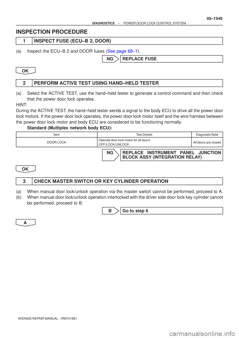
1 INSPECT FUSE (ECU±B 2, DOOR)
(a)Inspect the ECU±B 2 and DOOR fuses (See page 68±1).
NG REPLACE FUSE
OK
2 PERFORM ACTIVE TEST USING HAND±HELD TESTER
(a) Select the ACTIVE TEST, use the hand±held tester to generate a control command and then check that the power door lock operates.
HINT:
During the ACTIVE TEST, the hand±held tester sends a signal to the body ECU to drive all th\
e power door
lock motors. If the power door lock operates, the power door lock motor itse\
lf and the wire harness between
the power door lock motor and body ECU are considered to be functioning nor\
mally. Standard (Multiplex network body ECU):
ItemTest DetailsDiagnostic Note
DOOR LOCKOperate door lock motor for all doors
OFF/LOCK/UNLOCKAll doors are closed
NG REPLACE INSTRUMENT PANEL JUNCTION BLOCK ASSY (INTEGRATION RELAY)
OK
3 CHECK MASTER SWITCH OR KEY CYLINDER OPERATION
(a) When manual door lock/unlock operation via the master switch cannot be p\
erformed, proceed to A.
(b) When manual door lock/unlock operation interlocked with the driver side door\
lock key cylinder cannot be performed, proceed to B.
B Go to step 6
A
Page 1627 of 5135
05C8A±01
±
DIAGNOSTICS POWER DOOR LOCK CONTROL SYSTEM
05±1545
AVENSIS REPAIR MANUAL (RM1018E)
PROBLEM SYMPTOMS TABLE
SymptomSuspected AreaSee Page
All doors cannot be locked/unlocked at once
3. DOOR fuse
4. ECU±B 2 fuse
5. Power window regulator master switch assy
6. Front door lock assy LH, RH (Driver side)
7. Instrument panel J/B assy (Integration relay)
8. Wire harness
05±1546
Key lock±in prevention function does not work properly (Manual
operation and operation interlocked with key are active)
1. Unlock warning switch assy
2. Courtesy lamp switch assy LH, RH (Driver side)
3. Instrument panel J/B assy (Integration relay)
4. Wire harness
05±1555
w/ Double lock:
Double lock function does not operate properly
1. Wireless system
2. DOOR fuse
3. ECU±B 2 fuse
4. Front door lock assy LH, RH
5. Rear door lock assy LH, RH
6. Instrument panel J/B assy (Integration relay)
7. Wire harness
05±1560
Page 1640 of 5135

± DIAGNOSTICSENGINE IMMOBILISER SYSTEM
05±1603
AVENSIS REPAIR MANUAL (RM1018E)
3. CHECK DIAGNOSIS
(a) Using the hand±held tester, check for DTCs.
NOTICE:
Hand±held tester only:
When the diagnosis system is switched from normal mode to check mode, all the DTCs and freeze
frame data recorded in normal mode are erased. So before switching modes, always check the DTCs
and freeze frame data, and make a note of them.
(1) Prepare the hand±held tester.
(2) Connect the hand±held tester to the DLC3 under the instrument panel lower pad.
(3) Turn the ignition switch ON and push the hand±held tester switch ON.
(4) Use the hand±held tester to check for DTCs and freeze frame data, and make a note of them
(For operating instructions, see the hand±held tester instruction book).
(5) Confirm the details of the DTCs.
(b) Either of the following procedures will erase the DTCs and freeze frame data.
(1) Operating the hand±held tester to erase the codes (See the hand±held tester instruction book
for operating instructions).
(2) Disconnecting the battery terminals or ECU±B fuse.
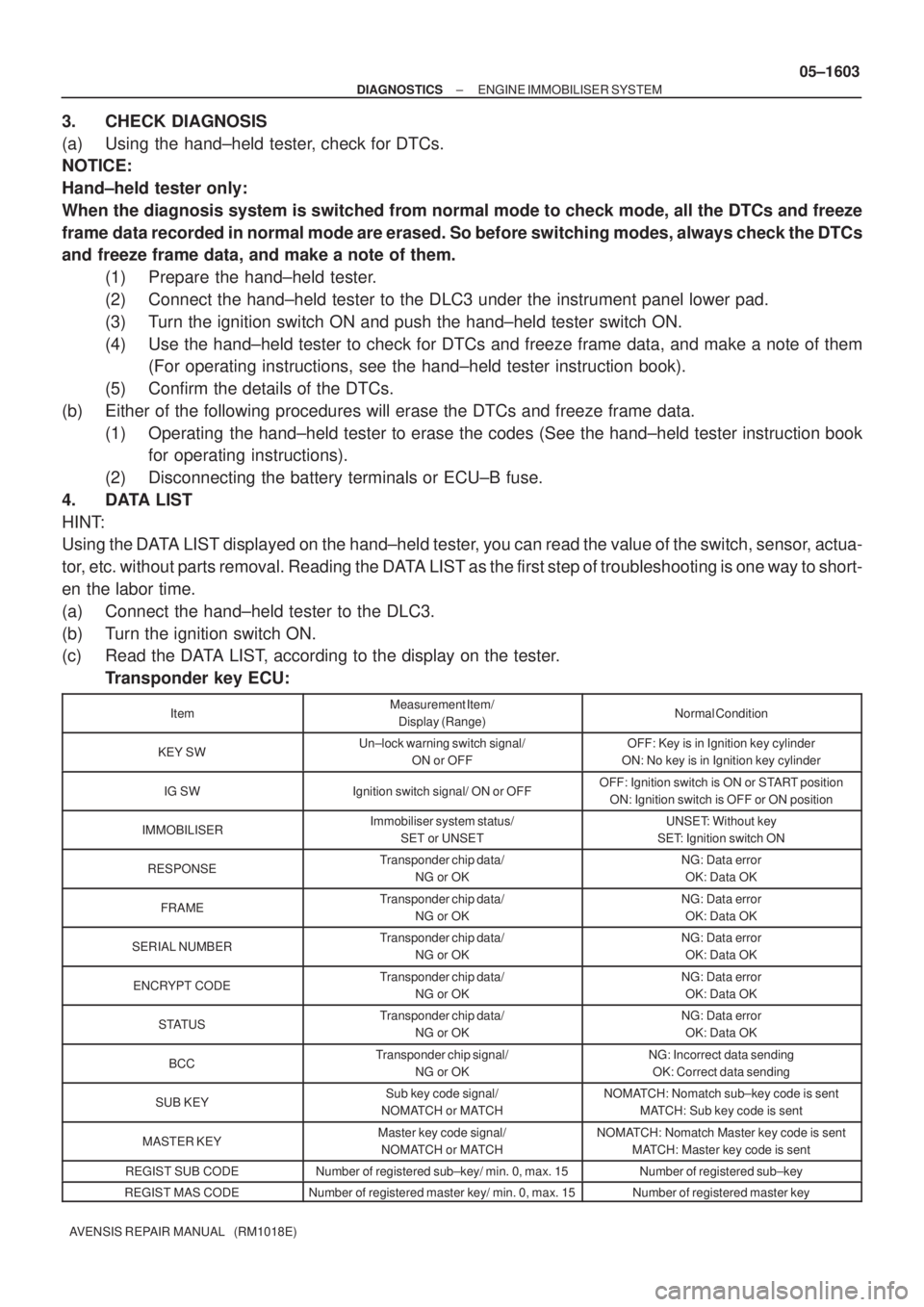
4. DATA LIST
HINT:
Using the DATA LIST displayed on the hand±held tester, you can read the value of the switch, sensor, actua-
tor, etc. without parts removal. Reading the DATA LIST as the first step of troubleshooting is one way to short-
en the labor time.
(a) Connect the hand±held tester to the DLC3.
(b) Turn the ignition switch ON.
(c) Read the DATA LIST, according to the display on the tester.
Transponder key ECU:
ItemMeasurement Item/
Display (Range)Normal Condition
KEY SWUn±lock warning switch signal/
ON or OFFOFF: Key is in Ignition key cylinder
ON: No key is in Ignition key cylinder
IG SWIgnition switch signal/ ON or OFFOFF: Ignition switch is ON or START position
ON: Ignition switch is OFF or ON position
IMMOBILISERImmobiliser system status/
SET or UNSETUNSET: Without key
SET: Ignition switch ON
RESPONSETransponder chip data/
NG or OKNG: Data error
OK: Data OK
FRAMETransponder chip data/
NG or OKNG: Data error
OK: Data OK
SERIAL NUMBERTransponder chip data/
NG or OKNG: Data error
OK: Data OK
ENCRYPT CODETransponder chip data/
NG or OKNG: Data error
OK: Data OK
STATUSTransponder chip data/
NG or OKNG: Data error
OK: Data OK
BCCTransponder chip signal/
NG or OKNG: Incorrect data sending
OK: Correct data sending
SUB KEYSub key code signal/
NOMATCH or MATCHNOMATCH: Nomatch sub±key code is sent
MATCH: Sub key code is sent
MASTER KEYMaster key code signal/
NOMATCH or MATCHNOMATCH: Nomatch Master key code is sent
MATCH: Master key code is sent
REGIST SUB CODENumber of registered sub±key/ min. 0, max. 15Number of registered sub±key
REGIST MAS CODENumber of registered master key/ min. 0, max. 15Number of registered master key