Page 2376 of 5135
1606N±03
A57065
21
��
± COOLINGCOOLING FAN SYSTEM (1CD±FTV)
16±41
AVENSIS REPAIR MANUAL (RM1018E)
COOLING FAN SYSTEM (1CD±FTV)
ON±VEHICLE INSPECTION
1. CHECK COOLING FAN OPERATION WITH LOW TEMPERATURE (Below 83�C (181�F))
(a) Turn the ignition switch ON.
(b) Check that the cooling fan stops.
(c) Disconnect the temperature detect switch connector.
(d) Connect the terminals on the temperature detect switch connector.
(e) Check that the cooling fan rotates.
If not, check the fuses, cooling fan relay and cooling fan, and check for a open circuit between the cooling
fan relay and temperature detect switch.
(f) Reconnect the temperature detect switch connector.
2. CHECK COOLING FAN OPERATION WITH HIGH TEMPERATURE (Above 93�C (199�F))
(a) Start the engine, and raise coolant temperature to above 93�C (199�F)
HINT:
Coolant temperature is the detected value by the temperature detect switch on the radiator lower tank.
(b) Check that the cooling fan rotates.
If not, replace the temperature detect switch.
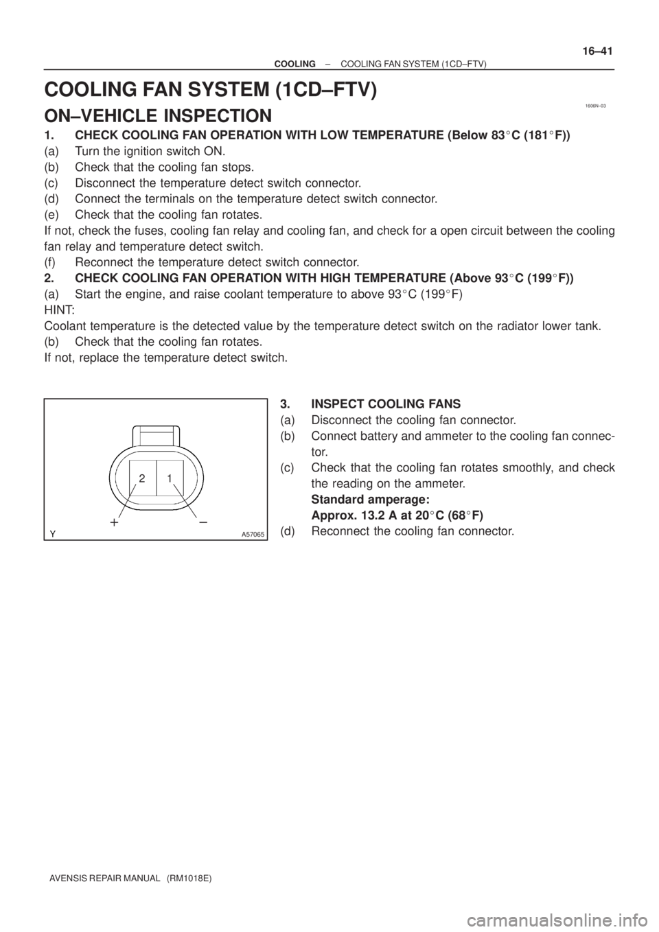
3. INSPECT COOLING FANS
(a) Disconnect the cooling fan connector.
(b) Connect battery and ammeter to the cooling fan connec-
tor.
(c) Check that the cooling fan rotates smoothly, and check
the reading on the ammeter.
Standard amperage:
Approx. 13.2 A at 20�C (68�F)
(d) Reconnect the cooling fan connector.
Page 2388 of 5135
1600R±12
± COOLINGCOOLING FAN SYSTEM (1AZ±FSE)
16±29
AVENSIS REPAIR MANUAL (RM1018E)
COOLING FAN SYSTEM (1AZ±FSE)
ON±VEHICLE INSPECTION
HINT:
It is normal that the cooling fan sometime rotates when the ignition switch is turned from ACC to ON.
1. CHECK COOLING FAN OPERATION WITH LOW TEMPERATURE (Below 83�C (181�F))
(a) Turn the ignition switch ON.
(b) Check that the cooling fan stops.
If not, check the cooling fan relay and engine coolant temperature sensor, and check for disconnection of
connectors or wire break between the cooling fan relay and engine coolant temperature sensor.
(c) Disconnect the engine coolant temperature sensor connector.
(d) Check that the cooling fan rotates.
If not, check the fuses, cooling fan relay, ECM and cooling fan, and check for a short circuit between the
cooling fan relay and engine coolant temperature sensor.
(e) Reconnect the engine coolant temperature sensor connector.
2. CHECK COOLING FAN OPERATION WITH HIGH TEMPERATURE (Above 100�C (212�F))
(a) Start the engine, and raise coolant temperature to above 100�C (212�F).
HINT:
Coolant temperature is the detected value by the engine coolant temperature sensor on the water outlet.
(b) Check that the cooling fan rotates.
If not, replace the engine coolant temperature sensor.
3. INSPECT COOLING FAN
(a) Disconnect the cooling fan connector.
(b) Connect battery and ammeter to the cooling fan connector.
(c) Check that the cooling fan rotates smoothly, and check the reading on the ammeter.
Standard amperage:
5.2 to 8.2 A at 20�C (68�F) (M/T)
8.3 to 11.3 A at 20�C (68�F) (A/T)
(d) Reconnect the cooling fan connector.
4. INSPECT COOLING FAN No.2 (With Air Conditioner)
(a) Disconnect the cooling fan connector.
(b) Connect battery and ammeter to the cooling fan connector.
(c) Check that the cooling fan rotates smoothly, and check the reading on the ammeter.
Standard amperage:
5.2 to 8.2 A at 20�C (68�F) (M/T)
8.3 to 11.3 A at 20�C (68�F) (A/T)
(d) Reconnect the cooling fan connector.
Page 2433 of 5135
190NQ±01
A81052
������������A82936
Type A
Type B
BlueWhite
Red Green DarkClear or
light yellow
B00543
± STARTING & CHARGINGCHARGING SYSTEM (1ZZ±FE/3ZZ±FE)
19±5
AVENSIS REPAIR MANUAL (RM1018E)
ON±VEHICLE INSPECTION
1. CHECK BATTERY ELECTROLYTE LEVEL
(a) Check the electrolyte quantity of each cell.
(1) If the electrolyte is under the low level, replace the battery (or add distilled water if possible) and
check the charging system.
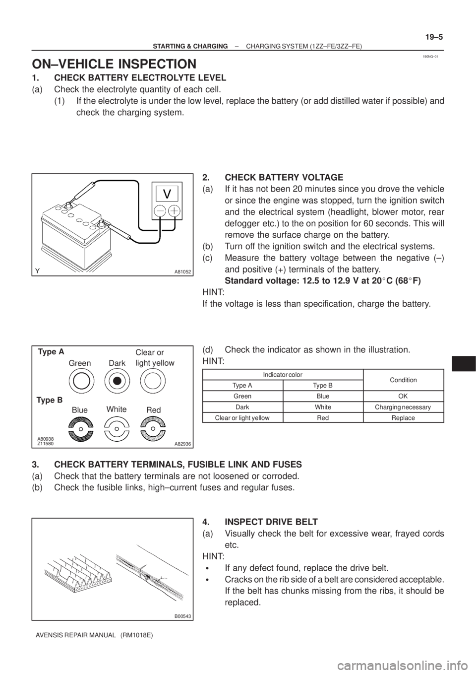
2. CHECK BATTERY VOLTAGE
(a) If it has not been 20 minutes since you drove the vehicle
or since the engine was stopped, turn the ignition switch
and the electrical system (headlight, blower motor, rear
defogger etc.) to the on position for 60 seconds. This will
remove the surface charge on the battery.
(b) Turn off the ignition switch and the electrical systems.
(c) Measure the battery voltage between the negative (±)
and positive (+) terminals of the battery.
Standard voltage: 12.5 to 12.9 V at 20�C (68�F)
HINT:
If the voltage is less than specification, charge the battery.
(d) Check the indicator as shown in the illustration.
HINT:
Indicator colorConditionType AType BCondition
GreenBlueOK
DarkWhiteCharging necessary
Clear or light yellowRedReplace
3. CHECK BATTERY TERMINALS, FUSIBLE LINK AND FUSES
(a) Check that the battery terminals are not loosened or corroded.
(b) Check the fusible links, high±current fuses and regular fuses.
4. INSPECT DRIVE BELT
(a) Visually check the belt for excessive wear, frayed cords
etc.
HINT:
�If any defect found, replace the drive belt.
�Cracks on the rib side of a belt are considered acceptable.
If the belt has chunks missing from the ribs, it should be
replaced.
Page 2435 of 5135
190NP±01
19±4
± STARTING & CHARGINGCHARGING SYSTEM (1ZZ±FE/3ZZ±FE)
AVENSIS REPAIR MANUAL (RM1018E)
CHARGING SYSTEM (1ZZ±FE/3ZZ±FE)
PRECAUTION
1. Check that the battery cables are connected to the correct terminals.
2. Disconnect the battery cables when the battery is given a quick charge.
3. Do not perform tests with a high voltage insulation resistance tester.
4. Never disconnect the battery while the engine is running.
5. Check that the charging cable is tightened on terminal B of the generator and the fuse box.
Page 2469 of 5135
190NN±01
A81051
A81052
������������A82936
Type A
Type B
BlueWhite
Red Green DarkClear or
light yellow 19±26
± STARTING & CHARGINGCHARGING SYSTEM (1CD±FTV)
AVENSIS REPAIR MANUAL (RM1018E)
ON±VEHICLE INSPECTION
1. CHECK BATTERY ELECTROLYTE LEVEL
(a) Check the electrolyte quantity of each cell.
(1) If the electrolyte is under the low level, replace the battery (or add distilled water if possible) and
check the charging system.
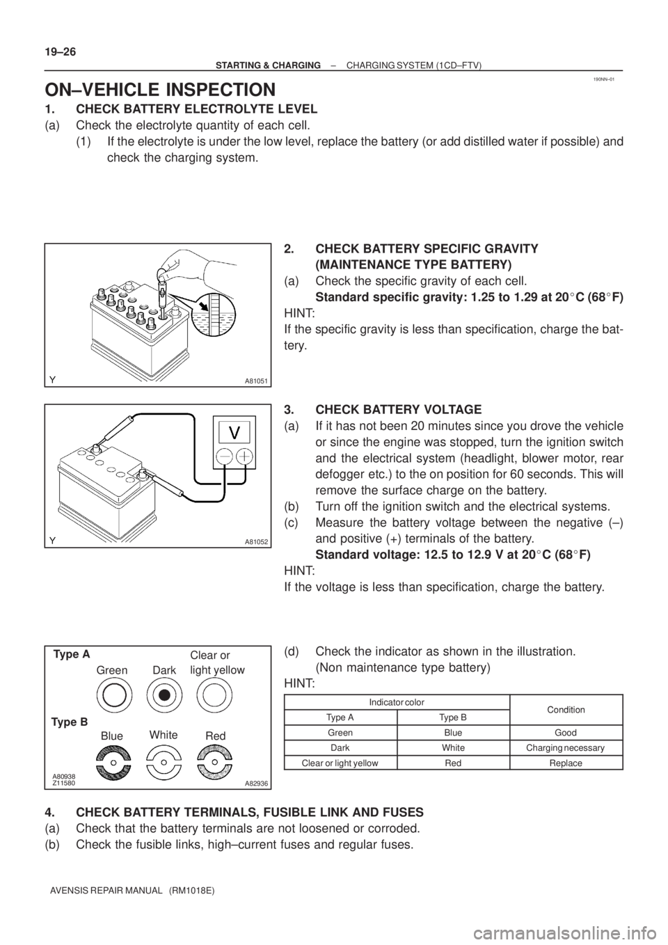
2. CHECK BATTERY SPECIFIC GRAVITY
(MAINTENANCE TYPE BATTERY)
(a) Check the specific gravity of each cell.
Standard specific gravity: 1.25 to 1.29 at 20�C (68�F)
HINT:
If the specific gravity is less than specification, charge the bat-
tery.
3. CHECK BATTERY VOLTAGE
(a) If it has not been 20 minutes since you drove the vehicle
or since the engine was stopped, turn the ignition switch
and the electrical system (headlight, blower motor, rear
defogger etc.) to the on position for 60 seconds. This will
remove the surface charge on the battery.
(b) Turn off the ignition switch and the electrical systems.
(c) Measure the battery voltage between the negative (±)
and positive (+) terminals of the battery.
Standard voltage: 12.5 to 12.9 V at 20�C (68�F)
HINT:
If the voltage is less than specification, charge the battery.
(d) Check the indicator as shown in the illustration.
(Non maintenance type battery)
HINT:
Indicator colorConditionType AType BCondition
GreenBlueGood
DarkWhiteCharging necessary
Clear or light yellowRedReplace
4. CHECK BATTERY TERMINALS, FUSIBLE LINK AND FUSES
(a) Check that the battery terminals are not loosened or corroded.
(b) Check the fusible links, high±current fuses and regular fuses.
Page 2472 of 5135
190NM±01
± STARTING & CHARGINGCHARGING SYSTEM (1CD±FTV)
19±25
AVENSIS REPAIR MANUAL (RM1018E)
CHARGING SYSTEM (1CD±FTV)
PRECAUTION
1. Check that the battery cables are connected to the correct terminals.
2. Disconnect the battery cables when the battery is given a quick charge.
3. Do not perform tests with a high voltage insulation resistance tester.
4. Never disconnect the battery while the engine is running.
5. Check that the charging cable is tightened on terminal B of the generator and the fuse box.
Page 2478 of 5135
190NT±01
A81052
������������A82936
Type A
Type B
BlueWhite
Red Green DarkClear or
light yellow
B00543
19±18
± STARTING & CHARGINGCHARGING SYSTEM (1AZ±FSE)
AVENSIS REPAIR MANUAL (RM1018E)
ON±VEHICLE INSPECTION
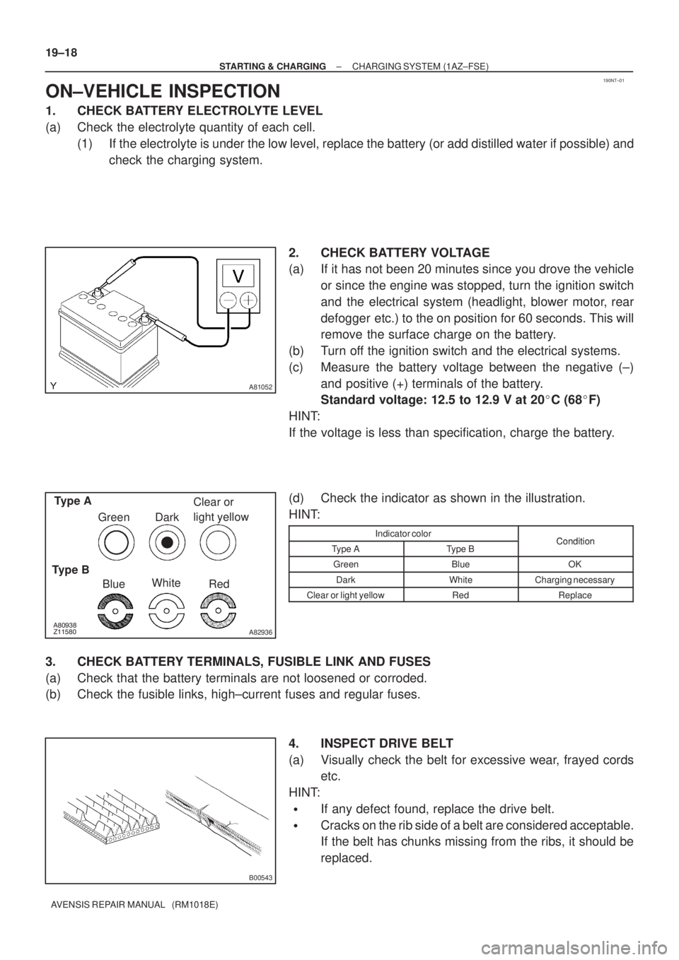
1. CHECK BATTERY ELECTROLYTE LEVEL
(a) Check the electrolyte quantity of each cell.
(1) If the electrolyte is under the low level, replace the battery (or add distilled water if possible) and
check the charging system.
2. CHECK BATTERY VOLTAGE
(a) If it has not been 20 minutes since you drove the vehicle
or since the engine was stopped, turn the ignition switch
and the electrical system (headlight, blower motor, rear
defogger etc.) to the on position for 60 seconds. This will
remove the surface charge on the battery.
(b) Turn off the ignition switch and the electrical systems.
(c) Measure the battery voltage between the negative (±)
and positive (+) terminals of the battery.
Standard voltage: 12.5 to 12.9 V at 20�C (68�F)
HINT:
If the voltage is less than specification, charge the battery.
(d) Check the indicator as shown in the illustration.
HINT:
Indicator colorConditionType AType BCondition
GreenBlueOK
DarkWhiteCharging necessary
Clear or light yellowRedReplace
3. CHECK BATTERY TERMINALS, FUSIBLE LINK AND FUSES
(a) Check that the battery terminals are not loosened or corroded.
(b) Check the fusible links, high±current fuses and regular fuses.
4. INSPECT DRIVE BELT
(a) Visually check the belt for excessive wear, frayed cords
etc.
HINT:
�If any defect found, replace the drive belt.
�Cracks on the rib side of a belt are considered acceptable.
If the belt has chunks missing from the ribs, it should be
replaced.
Page 2480 of 5135
190NS±01
± STARTING & CHARGINGCHARGING SYSTEM (1AZ±FSE)
19±17
AVENSIS REPAIR MANUAL (RM1018E)
CHARGING SYSTEM (1AZ±FSE)
PRECAUTION
1. Check that the battery cables are connected to the correct terminals.
2. Disconnect the battery cables when the battery is given a quick charge.
3. Do not perform tests with a high voltage insulation resistance tester.
4. Never disconnect the battery while the engine is running.
5. Check that the charging cable is tightened on terminal B of the generator and the fuse box.