Page 1661 of 5135
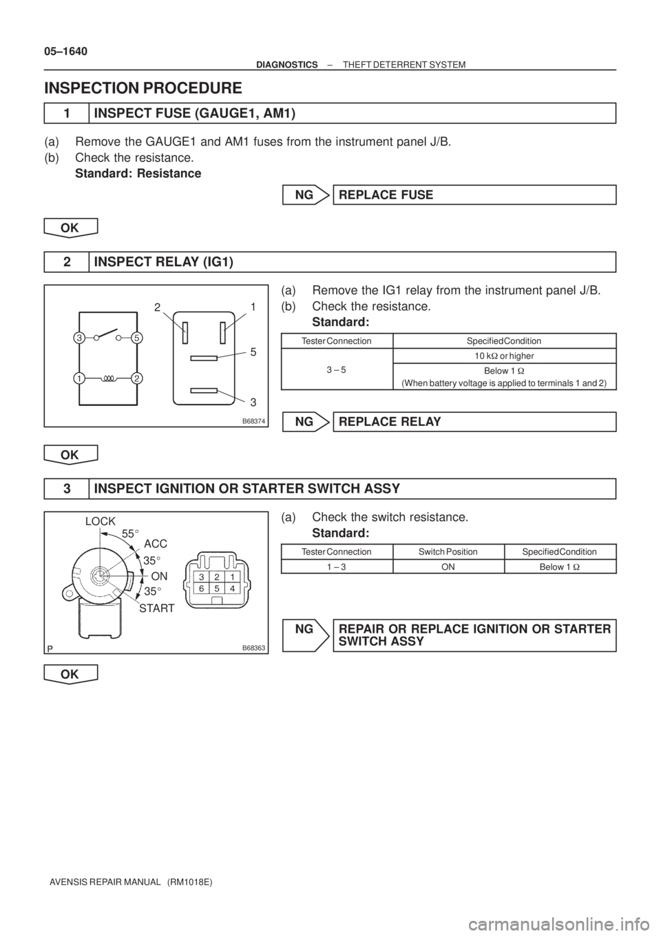
B68374
21
5
3
B68363
ACC LOCK
ON
START35� 35� 55�
05±1640
± DIAGNOSTICSTHEFT DETERRENT SYSTEM
AVENSIS REPAIR MANUAL (RM1018E)
INSPECTION PROCEDURE
1 INSPECT FUSE (GAUGE1, AM1)
(a) Remove the GAUGE1 and AM1 fuses from the instrument panel J/B.
(b) Check the resistance.
Standard: Resistance
NG REPLACE FUSE
OK
2 INSPECT RELAY (IG1)
(a) Remove the IG1 relay from the instrument panel J/B.
(b) Check the resistance.
Standard:
Tester ConnectionSpecified Condition
10 k�or higher
3 ± 5Below 1 �
(When battery voltage is applied to terminals 1 and 2)
NG REPLACE RELAY
OK
3 INSPECT IGNITION OR STARTER SWITCH ASSY
(a) Check the switch resistance.
Standard:
Tester ConnectionSwitch PositionSpecified Condition
1 ± 3ONBelow 1 �
NG REPAIR OR REPLACE IGNITION OR STARTER
SWITCH ASSY
OK
Page 1663 of 5135
B67693
+B1
E W±R B±W
1A5
3DCCEngine Room R/B 1IP1
B*
2
BatteryJ/C
IPW±B
29 Center J/B 6T6
Theft Warning ECU Assy
CG 6J26 W±R
J27 6 Fuse Block
DOME
B±W
34A
4B B±G*
1
B±G*1B*2
3.0W Engine
Room R/B
No. 3CA W±B9
*
1: Gasoline
*2: 1CD±FTV 2 1
1 2
1
1FH
2
Engine
Room J/B
No. 4
± DIAGNOSTICSTHEFT DETERRENT SYSTEM
05±1637
AVENSIS REPAIR MANUAL (RM1018E)
ECU POWER SOURCE CIRCUIT
CIRCUIT DESCRIPTION
This circuit provides power to operate the theft warning ECU.
WIRING DIAGRAM
05BAC±01
Page 1664 of 5135

INSPECTION PROCEDU")
B63408
Wire Harness Side
T6
Theft Warning ECU Assy
B63408
Wire Harness Side
T6
Theft Warning ECU Assy
05±1638
± DIAGNOSTICSTHEFT DETERRENT SYSTEM
AVENSIS REPAIR MANUAL (RM1018E)
INSPECTION PROCEDURE
1 INSPECT FUSE (DOME, DCC)
(a) Remove the DCC fuse from the engine room R/B.
(b) Remove the DOME fuse from the fuse block.
(c) Check the resistance.
Standard: Resistance
NG REPLACE FUSE
OK
2 CHECK THEFT WARNING ECU ASSY (POWER SOURCE)
(a) Disconnect the T6 ECU connector.
(b) Check the voltage between the wire harness side con-
nector and the body ground.
Standard:
Tester ConnectionSpecified Condition
T6±2 (+B1) ± Body ground10 to 14 V
NG REPAIR OR REPLACE HARNESS AND
CONNECTOR
OK
3 CHECK WIRE HARNESS (THEFT WARNING ECU ASSY ± BODY GROUND)
(a) Disconnect the T6 ECU connector.
(b) Check the resistance between the wire harness side con-
nector and the body ground.
Standard:
Tester ConnectionSpecified Condition
T6±29 (E) ± Body groundBelow 1 �
NG REPAIR OR REPLACE HARNESS AND
CONNECTOR
OK
REPLACE THEFT WARNING ECU ASSY
Page 1671 of 5135
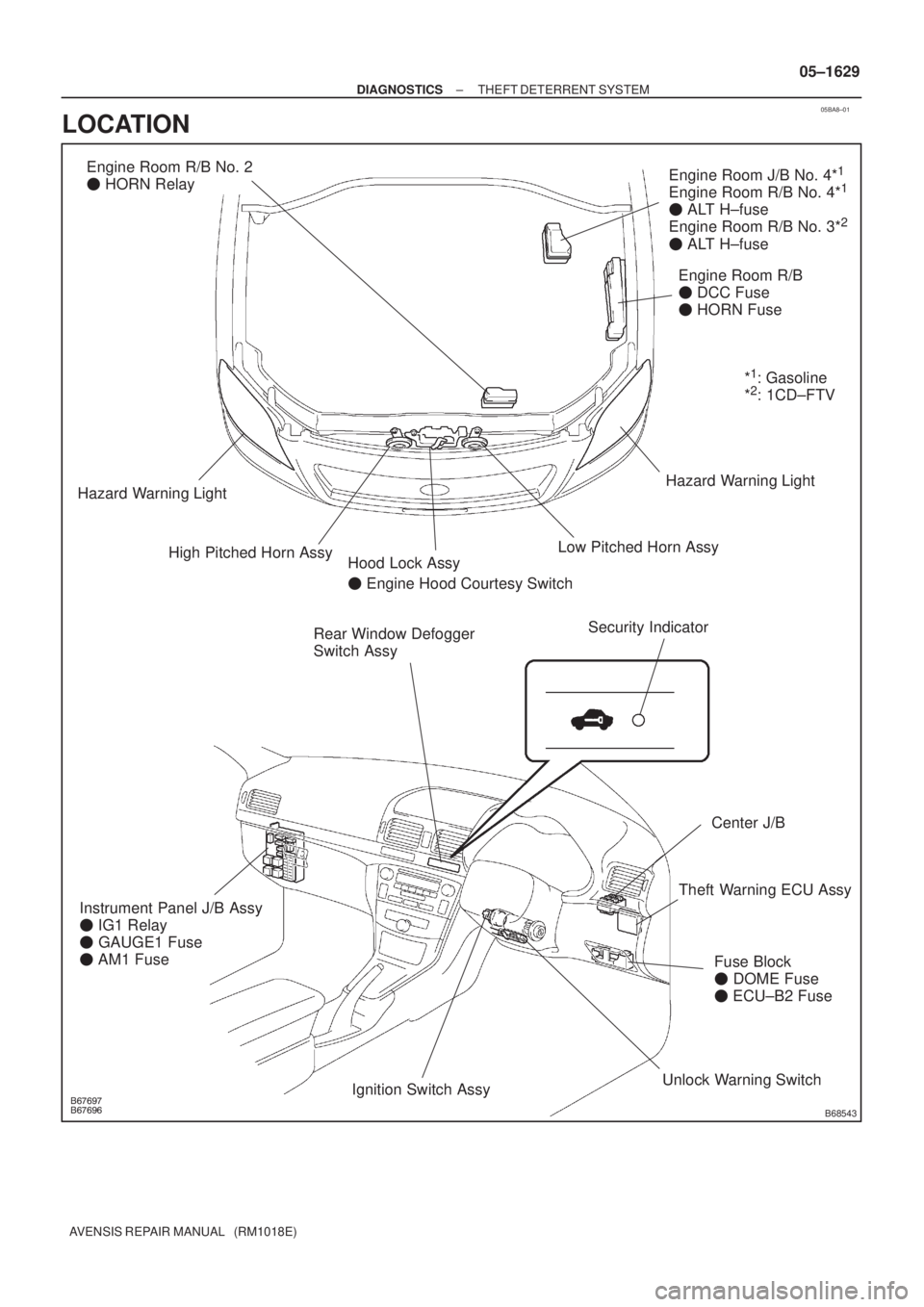
05BA8±01
������
������B68543
Rear Window Defogger
Switch AssyEngine Room R/B
� DCC Fuse
� HORN Fuse
Fuse Block
� DOME Fuse
� ECU±B2 Fuse
Center J/B
Security Indicator
Engine Room J/B No. 4*1
Engine Room R/B No. 4*1
� ALT H±fuse
Engine Room R/B No. 3*2
� ALT H±fuse
Engine Room R/B No. 2
� HORN Relay
High Pitched Horn AssyLow Pitched Horn AssyHazard Warning Light
Hazard Warning Light
Instrument Panel J/B Assy
� IG1 Relay
� GAUGE1 Fuse
� AM1 FuseHood Lock Assy
� Engine Hood Courtesy Switch
Theft Warning ECU Assy
Unlock Warning Switch
Ignition Switch Assy*
1: Gasoline
*2: 1CD±FTV
± DIAGNOSTICSTHEFT DETERRENT SYSTEM
05±1629
AVENSIS REPAIR MANUAL (RM1018E)
LOCATION
Page 1690 of 5135
B67807
Main
Battery 131
+B1MPX
E Theft Warning ECU Assy
B*
2
2H 5J/C
IP2 T6
W±R
B±G*
1
1A6
T6 IP1
B±W
CG B±W
1
*
1: Except 1CD±FTV
*2: 1CD±FTV BEAN
(SECURITY)
3W±B 1Combination Meter Assy
(Combination Meter ECU)
P±L
C1015
J27
J26F
W±R
6
1 DOME
2
T6 29
CA9
6
W±B *
2
B
*1
B±G
4A
4B
31
1
Engine Room J/B No. 4*1
Engine Room R/B
Engine Room
R/B No. 3*
2
Center J/B Fuse Block Assy
DCC 05±1690
± DIAGNOSTICSMULTIPLEX COMMUNICATION SYSTEM
AVENSIS REPAIR MANUAL (RM1018E)
WIRING DIAGRAM
Page 1694 of 5135
B67808
Battery 120
J17
J/C+BMPX±
A1110
ECU±B 2
34IC1
CG DCCA15
P±B
IE4
3A13 I14
W±R
IK6CF7
B±W2
2
Main6 1Instrument Panel J/B Assy
(Integration Relay)
P
1A10A/C Control Assy
(A/C ECU)
A13
29
P
MPX1
MPX+ 10
A159
E10 29
29 21
E9
E9 MPX2
A132 24
A16 CC
6
1
3B*
5
B*5
GND
A13 40 13
A16 W±B*7
W±B*6
CA
IP*
1: Except Automatic A/C
*2: Automatic A/C
*
3: 1AZ±FSE
*
4: 1AZ±FE, 1ZZ±FE, 3ZZ±FE
*5: 1CD±FTV
*
6: LHD
*7: RHD ECM*
2
*1
*1
*2 *3
*4 *5
*1
*2
*2 *1
Center J/B
W±R Fuse Block Assy
B±W
Engine Room R/B No. 3*5
Engine Room R/B
Center J/B
*3,
4
B±GEngine Room J/B No. 4*3,
4
B±G*3,
4
4B 4A
1
1 5
IP1
1
A
W±B*
7
W±B*6
*6*7
J15
J/C A 05±1686
± DIAGNOSTICSMULTIPLEX COMMUNICATION SYSTEM
AVENSIS REPAIR MANUAL (RM1018E)
WIRING DIAGRAM
Page 1723 of 5135
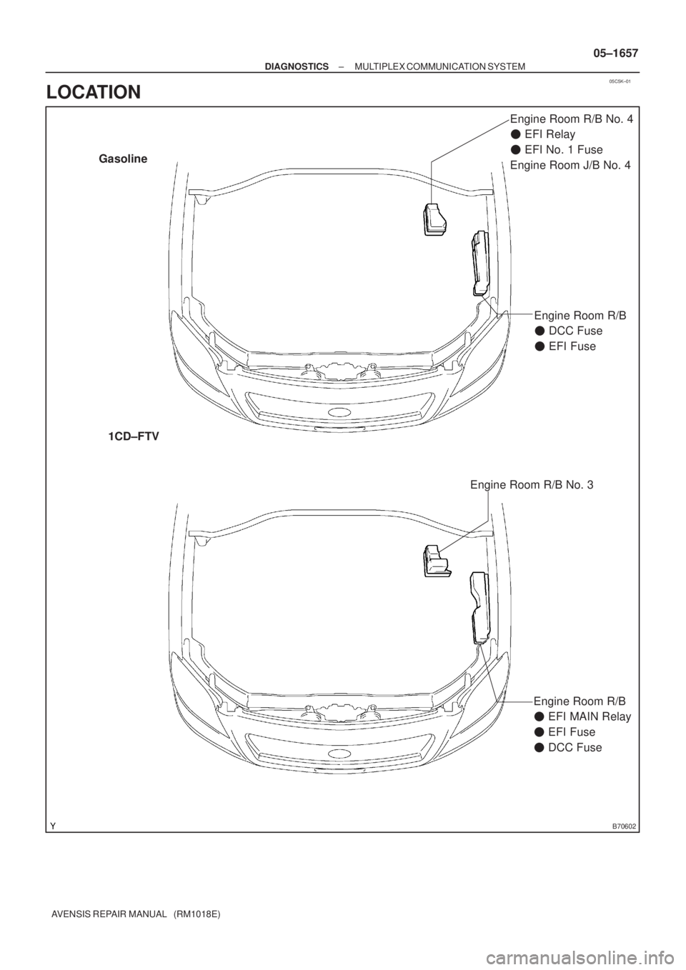
05C5K±01
B70602
Engine Room R/B No. 4
�EFI Relay
�EFI No. 1 Fuse
Engine Room J/B No. 4 Gasoline
1CD±FTV
Engine Room R/B
�DCC Fuse
�EFI Fuse
Engine Room R/B No. 3
Engine Room R/B
�EFI MAIN Relay
�EFI Fuse
�DCC Fuse
± DIAGNOSTICSMULTIPLEX COMMUNICATION SYSTEM
05±1657
AVENSIS REPAIR MANUAL (RM1018E)
LOCATION
Page 1724 of 5135
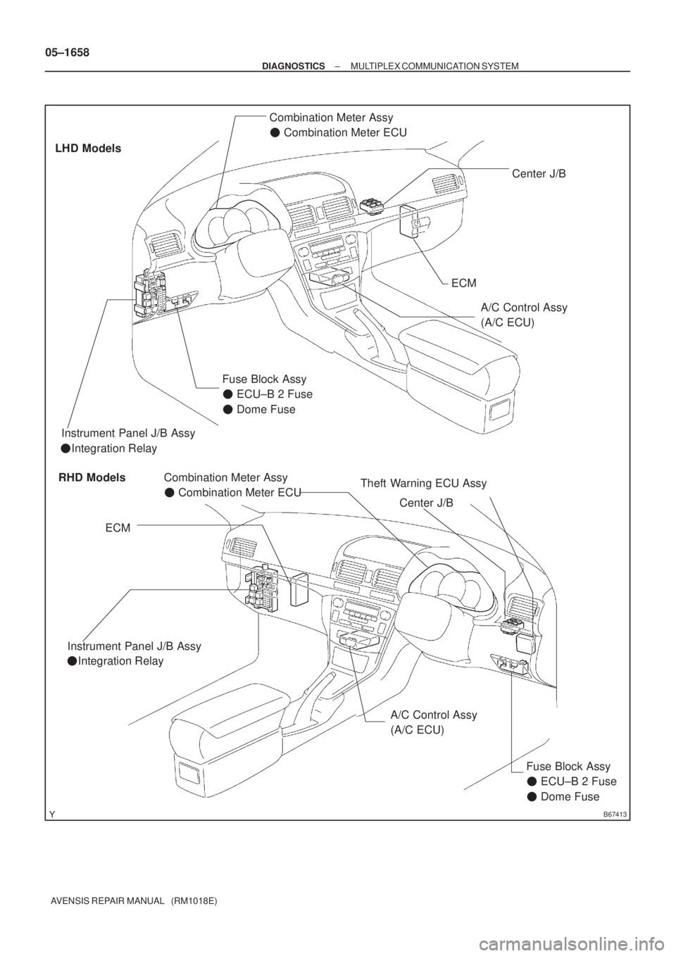
B67413
RHD Models LHD Models
�Integration Relay Instrument Panel J/B Assy
Instrument Panel J/B Assy
�Integration Relay
ECM
A/C Control Assy
(A/C ECU)
ECM
Theft Warning ECU Assy
A/C Control Assy
(A/C ECU) Combination Meter Assy
�Combination Meter ECU
Center J/B
Fuse Block Assy
�ECU±B 2 Fuse
�Dome Fuse
Combination Meter Assy
�Combination Meter ECU
Center J/B
Fuse Block Assy
�ECU±B 2 Fuse
�Dome Fuse
05±1658
± DIAGNOSTICSMULTIPLEX COMMUNICATION SYSTEM
AVENSIS REPAIR MANUAL (RM1018E)


3W±B 1Combination Meter Assy
(Com")

P
1A10A/C Control Assy
(A/C ECU)
A13
29
P")