Page 1495 of 5135
I34727
Center J/B
10
CB4
CEL±Y (*3)
L±Y (*4)
(*3) L±YFuse Block
66
21RAD No.2J/C
EE
J24 J25L±Y
(*4)N69Navigation ECU
B±W
B±W+B
Engine Room R/B No.1 and Engine Room J/B No.1
45
IF4 IF1 B±W
(*3) (*4) 1
1
12 1ADCC B (*2)
B±G (*1)
I13
Ignition SW
32
AM1 ACC
G±R34
11 DH
DH DNDB RAD No.1
AM1 GGRDriver Side J/B
FF FF
(*3) (*4)J8 J20
(*3) (*4)J8 J20GR18
N6ACC
B±L (*2) W (*2)
ED11
Engine Room R/B J/B
1
4A
1
4BALT
121
4D B±G (*1) B±G (*1)
B (*2)
B (*2)3
33ALT
12
FL MAIN
Battery
IP W (*2)W (*2)
Center J/B
W±B6
CA13
7
10 CF
CK
CHW±B (*3)
W±B
(*4)7
17 N5
N6SNSE
GND
*1: Gasoline
*2: 1CD±FTV*3: LHD
*4: RHDJ/C
Engine Room R/B No.3
W±B
± DIAGNOSTICSNAVIGATION SYSTEM
05±1467
AVENSIS REPAIR MANUAL (RM1018E)
POWER SOURCE CIRCUIT (NAVIGATION ECU)
WIRING DIAGRAM
05C3I±01
Page 1497 of 5135

B±G
(*1)
B±RDriver Side J/B
1
DH
DB DH
DH
DNDA
DB 3
5
1AM1
4
9
7 GAUGE1 1
2
53RAD No.1
IG1 RelayGR (*3)
HH F FJ/B
J9 J21 J8 J20
(*")
I34729
G±R
I13
Ignition SW
ACC
IG1
ST2 AM2
AM1
G±R
3
41
B±L (*2)
B±G
(*1)
B±RDriver Side J/B
1
DH
DB DH
DH
DNDA
DB 3
5
1AM1
4
9
7 GAUGE1 1
2
53RAD No.1
IG1 RelayGR (*3)
HH F FJ/B
J9 J21 J8 J20
(*3) (*4) (*3) (*4)GR (*4)
GR
GRFF
J8 J20
(*3) (*4)
W±BMulti±display
(CRT Display) Display
14
M1 ACC
R±WCenter J/B
73
CA CFR±W3
M1
M1 15IG
ST1 B±W
Fuse Block
B±Y
6
6
6612
12ST
RAD No.2
B±W L±Y
(*3)L±Y
(*3) Center J/B
49
CE CB
J/C
L±Y
(*4) L±Y (*4)EE
J24 J251
M1
M1+B1
GND1 W±B
W±B25
Center J/B
56
CG CA
W±B
IP IJ B±G
(*1) 1
4A
1
2 1
4D
1
4B B±G (*1)
B±G (*1)ALT Engine Room J/B
1
2ALT
3
3
3 1
ED1B
(*2) B±L
(*2)W
(*2)
B (*2)
B±W
45
IE4 IP1B±W Engine Room R/B No.1 and Engine Room J/B No.1
(*3) (*4)
1
1
IE4 IP1 B±R
B±R
Battery1
11 DCC
AM21 2
1 2B
(*2)
B±G
(*1) 1A
*1: Gasoline
*2: 1CD±FTV*3: LHD
*4: RHD
G±Y
G
2
5
Engine Room R/B No.3
FL
MAIN
± DIAGNOSTICSNAVIGATION SYSTEM
05±1465
AVENSIS REPAIR MANUAL (RM1018E)
POWER SOURCE CIRCUIT (MULTI±DISPLAY (CRT DISPLAY)
DISPLAY)
WIRING DIAGRAM
05C3H±01
Page 1499 of 5135

PROBLEM SYMPTOMS TABLE
SymptomSuspect AreaSee page
Black screen
1. RAD No.2 fuse
2. Power source circuit (multi±d")
05C3G±01
05±1464
±
DIAGNOSTICS NAVIGATION SYSTEM
AVENSIS REPAIR MANUAL (RM1018E)
PROBLEM SYMPTOMS TABLE
SymptomSuspect AreaSee page
Black screen
1. RAD No.2 fuse
2. Power source circuit (multi±display (CRT display)dis- play)
3. AVC±LAN circuit01±5
05±1465
05±1471
Navigation screen display nothing
1. RAD No.2 fuse
2. Power source circuit (navigation ECU)
3. AVC±LAN circuit01±5
05±1467
05±1471
Navigation screen is not stabilized
(Synchronous error)1. RAD No.2 fuse
2. Power source circuit (navigation ECU)
3. Navigation screen is not stabilized (Synchronous error)01±5
05±1467
05±1475
Color on navigation screen is unusual
(RGB signal error)
1. RAD No.2 fuse
2. Power source circuit (navigation ECU)
3. Color on navigation screen is unusual (RGB signal er-
ror)01±5
05±1467
05±1477
Front speaker (driver side) only is not heard±05±1479
Map disc cannot be inserted1. RAD No.2 fuse
2. Power source circuit (navigation ECU)01±5
05±1467
Current position cannot be displayed on screen
(disc caution screen does not change)±05±1483
Map is displayed in white or blue screen
(switched and vehicle position mark are displayed)±05±1484
Vehicle position is deviated from correct point badly1. Vehicle position is deviated from correct point badly.
2. GPS mark does not appear.05±1485
05±1487
GPS mark does not appear±05±1487
Vehicle position mark rotates without control
(map rotates without control)±05±1488
Driving directions are opposite to moving direction of vehicle posi-
tion mark±05±1490
A navigation controller assy does not operate1. A navigation controller assy does not operate
2. The system cannot be operated by the voice sound05±1491
05±1494
When mount the navigation controller to the navigation controller
system, it cannot be operated
1. RAD No.2 fuse
2. Power source circuit (navigation controller holder)
3. When mount the navigation controller holder to the navi-
gation controller system, it cannot be operated
4. The system cannot be operated by the voice sound01±5
05±1469
05±1492
05±1494
The system cannot be operated by the voice sound1. The system cannot be operated by the voice sound
2. AVC±LAN circuit05±1494
05±1471
Page 1503 of 5135
05C3F±01
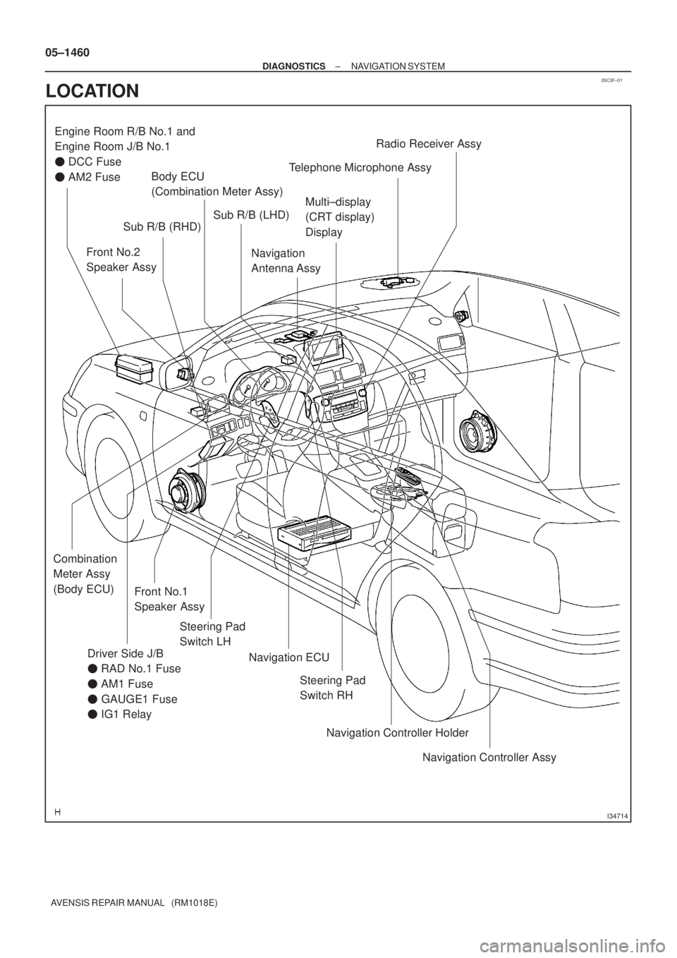
I34714
Driver Side J/B
� RAD No.1 Fuse
� AM1 Fuse
� GAUGE1 Fuse
� IG1 RelayFront No.1
Speaker AssyMulti±display
(CRT display)
Display
Steering Pad
Switch LH Engine Room R/B No.1 and
Engine Room J/B No.1
� DCC Fuse
� AM2 Fuse
Front No.2
Speaker Assy
Steering Pad
Switch RH Sub R/B (LHD)
Sub R/B (RHD)
Navigation
Antenna AssyTelephone Microphone AssyRadio Receiver Assy
Navigation Controller Assy Navigation Controller Holder Navigation ECU Combination
Meter Assy
(Body ECU)
Body ECU
(Combination Meter Assy)
05±1460
± DIAGNOSTICSNAVIGATION SYSTEM
AVENSIS REPAIR MANUAL (RM1018E)
LOCATION
Page 1531 of 5135
I34624
Front Seat Inner
Belt Assy LH
Occupant Detection Sensor
Front Seat Inner
Belt Assy RH
Passenger's Seat belt
Warning LampDriver Side R/BAccessary Meter
Combination Meter Assy
Driver Side J/B
Fuse Block
Center J/B
± DIAGNOSTICSCOMBINATION METER
05±1501
AVENSIS REPAIR MANUAL (RM1018E)
Page 1535 of 5135
Terminal No.
Wire harness side
Turn Signal Flasher Relay
Skid Control ECU with Actuator Brake Fluid Level Warning Switch
Engine ECU
Oil Pressure Switch
DOME Fuse Headlight Beam Level Control ECU
Skid Control ECU with Actuator
Skid Control ECU with Actuator Turn Signal Flasher Relay Engine ECU ± Multi Display RAD No.1 Fuse
GND
EMPS ECU
TAIL Fuse
Skid Control ECU with Actuator Fuel Sensor Gauge
Skid Control ECU with Actuator
± GND
Rear Fog Light Relay Front Fog Light Relay Multi Display Fuse Filter Warning Switch (*1)
IGN Fuse Fuel Sender Gauge
Engine Oil Level Sensor Security ECU Ambient Temp. Sensor
4P OUT (Other Parts) H±HI RH Fuse/H±LP RH Fuse 1
2
3
4
5
6
7
8
9
10
11
12
13
14
15
16
17
18
19
201
2
3
4
5
6
7
8
9
10
11
12
13
14
15
16
17
18
C10
Airbag Sensor Assembly GND
GAUGE1 Fuse Skid Control ECU with Actuator
C11Engine ECU
Integration Relay
21
22
*1: 1CD±FTVAmbient Temp. Sensor
± DIAGNOSTICSCOMBINATION METER
05±1505
AVENSIS REPAIR MANUAL (RM1018E)
Page 1557 of 5135
05C88±01
�����
�����
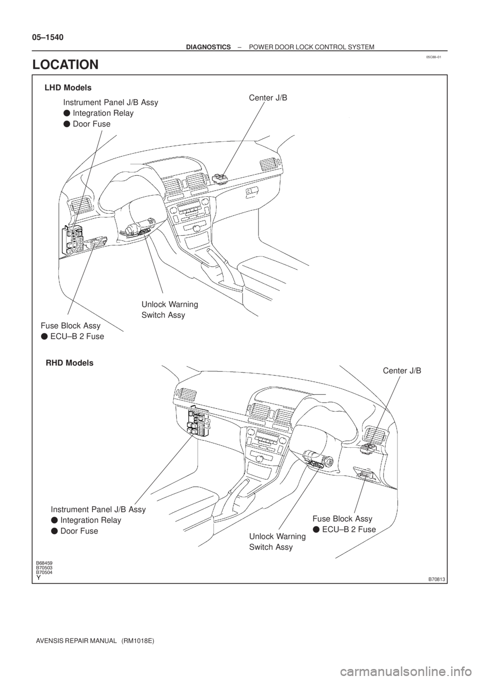
�����B70813
Unlock Warning
Switch Assy
Instrument Panel J/B Assy
� Integration Relay
� Door Fuse
Unlock Warning
Switch Assy
LHD Models
RHD ModelsCenter J/B
Center J/B
Fuse Block Assy
� ECU±B 2 Fuse
Instrument Panel J/B Assy
� Integration Relay
� Door FuseFuse Block Assy
� ECU±B 2 Fuse 05±1540
± DIAGNOSTICSPOWER DOOR LOCK CONTROL SYSTEM
AVENSIS REPAIR MANUAL (RM1018E)
LOCATION
Page 1572 of 5135
I35764
I14
Body ECUCombination Meter Assy
14
C10 1
IC1
P±B MPX2
P±B
MPX1 11
P 10
IC1 29
A13 20
A15
10 9
3 24
A16P±B MPX±
MPX+
PBLT A/C Control Assembly
F19 Front Passenger's
Seat Belt Warning LightECM
B10 Front Seat Inner Belt Assy
(Occupant Detection Sensor)
to GAUGE Fuse
*1: Except Automatic A/C
*2: Automatic A/C
*3: 1AZ±FSE
*4: 1AZ±FE, 1ZZ±FE, 3ZZ±FE
*5: 1CD±FTV
*6: Except 1AZ±FE21 29
E1029
(*5) (*3) (*4)MPX2
20 1823
13
J22
J/C
C
C 1 3
W±B (*6) G±Y B±PBEW
IG
PBEW
E1 2 5 3
L±R
A
AJ16
J/C
BS ILB
J30 C
J31J/C A15 A13
A13
(*5) (*3) (*4) (*2) (*1)
(*1) (*2)
(*1) (*2)E9
MPX1
P P
(*6) 8
IC3
G±Y (*6)
W±B (*6)
W±B (*6) W±B (*6) RHD Models:
22
(*6)
R±W (*6)
W±B
(*6)E9
E10
E9 E9 C10 05±1524
± DIAGNOSTICSCOMBINATION METER
AVENSIS REPAIR MANUAL (RM1018E)
SEAT BELT WARNING LAMP FOR FRONT PASSENGER'S SEAT
DOES NOT FLASH
WIRING DIAGRAM
05C4N±01

L±Y (*4)
(*3) L±YFuse Block
66
21RAD No.2J/C
EE
J24 J25L±Y
(*4)N69Navigation ECU
B±W
B±W+B
Engine Room R/B No.1 and Engine Room J/B No.1
45
IF4 IF1 B±W
(*3)")