Page 944 of 5135
![TOYOTA AVENSIS 2005 Service Repair Manual ± DIAGNOSTICSELECTRONIC CONTROLLED AUTOMATIC
TRANSAXLE [ECT] (U241E(1AZ±FSE))05±923
AVENSIS REPAIR MANUAL (RM1018E)
(8) Simulate the conditions of the malfunction de-
scribed by the customer.
NOT TOYOTA AVENSIS 2005 Service Repair Manual ± DIAGNOSTICSELECTRONIC CONTROLLED AUTOMATIC
TRANSAXLE [ECT] (U241E(1AZ±FSE))05±923
AVENSIS REPAIR MANUAL (RM1018E)
(8) Simulate the conditions of the malfunction de-
scribed by the customer.
NOT](/manual-img/14/57441/w960_57441-943.png)
± DIAGNOSTICSELECTRONIC CONTROLLED AUTOMATIC
TRANSAXLE [ECT] (U241E(1AZ±FSE))05±923
AVENSIS REPAIR MANUAL (RM1018E)
(8) Simulate the conditions of the malfunction de-
scribed by the customer.
NOTICE:
Leave the ignition switch ON until you have checked the
DTCs, etc.
(9) After simulating the malfunction conditions, use the
hand±held tester diagnosis selector to check the
DTCs and freeze frame data, etc.
HINT:
Take care not to turn the ignition switch OFF, as turning it off
switches the diagnosis system from Check mode to Normal
mode, which all DTCs etc. are erased.
(10) After checking the DTC, inspect the applicable cir-
cuit.
(b) Clear the DTC.
When using the hand±held tester:
The following operation will erase the DTC and freeze
frame data. Operate the hand±held tester to erase the
codes.
(c) Clear the DTC.
When not using the hand±held tester:
Remove the EFI fuse from engine room J/B for 10 se-
conds or more.
4. DATA LIST
HINT:
According to the DATA LIST displayed by the hand±held tester, you can read the value of the switch, sensor,
actuator and so on without parts removal. Reading the DATA LIST as the first step of troubleshooting is one
of the methods to shorten the work time.
(a) Warm up the engine.
(b) Turn the ignition switch OFF.
(c) Connect the hand±held tester to the DLC3.
(d) Turn the ignition switch ON.
(e) According to the display on tester, read the ºDATA LISTº.
ItemMeasurement Item/
Display (Range)Normal ConditionDiagnostic Note
STOP LIGHT SWStop light SW Status/
ON or OFF�Brake Pedal is depressed: ON
�Brake Pedal is released: OFF�
SHIFTActual Gear Position/
1st, 2nd, 3rd, 4th (O/D)Shift lever Range is;
�D: 1st, 2nd, 3rd or 4th (O/D)�
SPD (NC)Counter Gear Speed
display: 50 r/minD Range is warmed up,4th (O/D);
Same as input shaft speed�
LOCK UP SOLLock Up Solenoid Status/
ON or OFF�Lock Up: ON
�Except Lock Up: OFF�
KICKDOWN SWKick down SW Status/
ON or OFF
�Accelerator Pedal is depressed:
ON
�Accelerator Pedal is released:
OFF
�
Page 1086 of 5135
050WN±04
F45950
Driver Side J/B ECU±IG FusePower Steering ECU assy Steering Column Assy
Engine Room R/B No.1 and
Engine Room J/B No.1
Combination Meter Assy
(P/S Warning Light)
DLC3EMPS
Fuse
EMPS Relay
05±1056
± DIAGNOSTICSELECTRONIC MOTOR POWER STEERING SYSTEM
AVENSIS REPAIR MANUAL (RM1018E)
LOCATION
Page 1087 of 5135

050WM±04
05±1054
±
DIAGNOSTICS ELECTRONIC MOTOR POWER STEERING SYSTEM
AVENSIS REPAIR MANUAL (RM1018E)
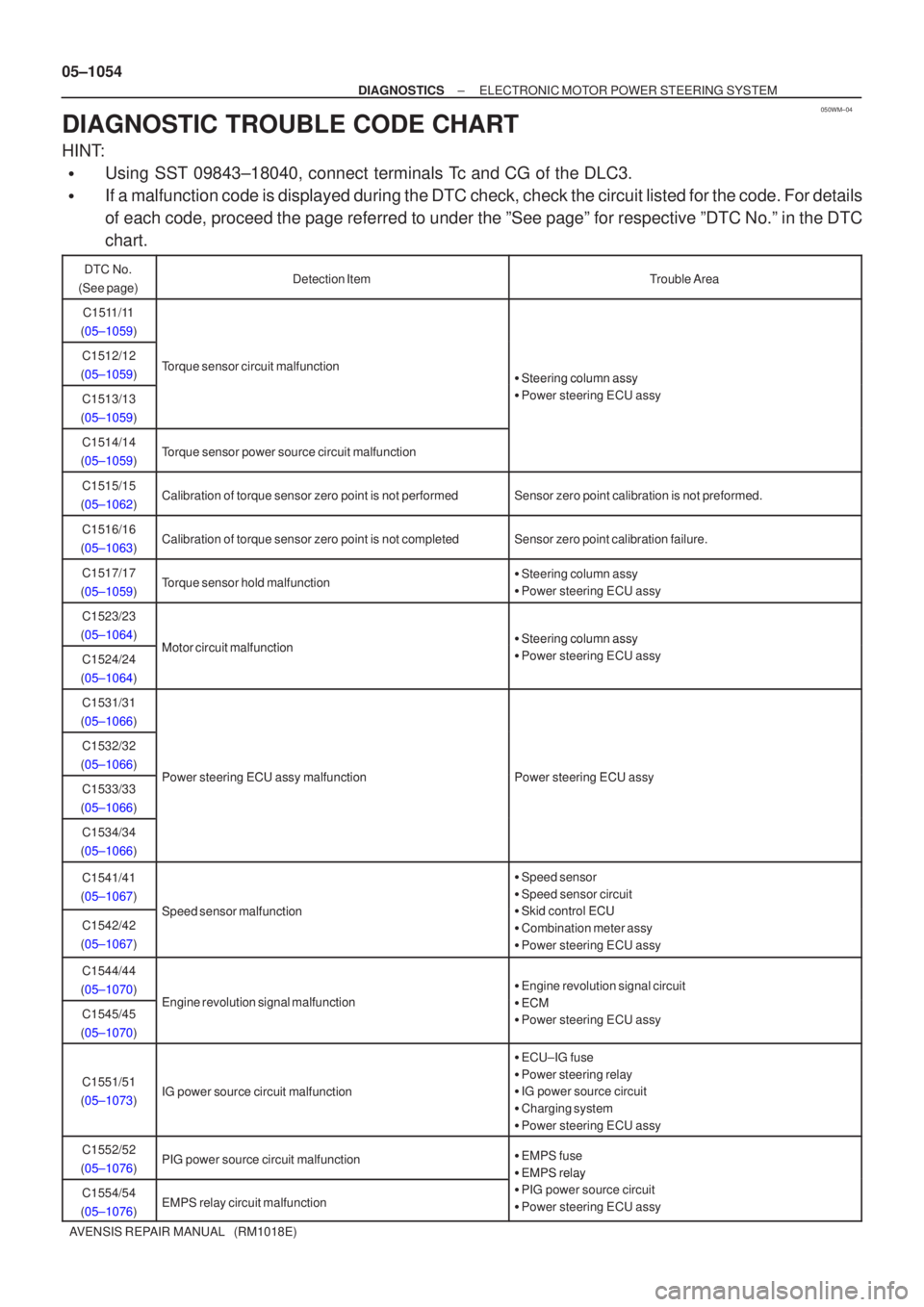
DIAGNOSTIC TROUBLE CODE CHART
HINT:
�Using SST 09843±18040, connect terminals Tc and CG of the DLC3.
�If a malfunction code is displayed during the DTC check, check the circuit\
listed for the code. For details
of each code, proceed the page referred to under the ºSee pageº for \
respective ºDTC No.º in the DTC
chart.
DTC No.
(See page)Detection ItemTrouble Area
C1511/11
(05±1059)
C1512/12
(05±1059)Torque sensor circuit malfunction� Steering column assy
C1513/13
(05±1059)
Steering column assy
� Power steering ECU assy
C1514/14
(05±1059)Torque sensor power source circuit malfunction
C1515/15
(05±1062)Calibration of torque sensor zero point is not performedSensor zero point calibration is not preformed.
C1516/16
(05±1063)Calibration of torque sensor zero point is not completedSensor zero point calibration failure.
C1517/17
(05±1059)Torque sensor hold malfunction� Steering column assy
� Power steering ECU assy
C1523/23
(05±1064)
Motor circuit malfunction� Steering column assy
C1524/24
(05±1064)Motor circuit malfunctionSteering column assy
� Power steering ECU assy
C1531/31
(05±1066)
C1532/32
(05±1066)
Power steering ECU assy malfunctionPower steering ECU assyC1533/33
(05±1066)Power steering ECU assy malfunctionPower steering ECU assy
C1534/34
(05±1066)
C1541/41
(05±1067)
Speed sensor malfunction
� Speed sensor
� Speed sensor circuit
�Skid control ECUC1542/42
(05±1067)Speed sensor malfunction� Skid control ECU
� Combination meter assy
� Power steering ECU assy
C1544/44
(05±1070)
Engine revolution signal malfunction
� Engine revolution signal circuit
ECMC1545/45
(05±1070)Engine revolution signal malfunction� ECM
� Power steering ECU assy
C1551/51
(05±1073)IG power source circuit malfunction
� ECU±IG fuse
� Power steering relay
� IG power source circuit
� Charging system
� Power steering ECU assy
C1552/52
(05±1076)PIG power source circuit malfunction� EMPS fuse
� EMPS rela
y
C1554/54
(05±1076)EMPS relay circuit malfunction
� EMPS relay
�PIG power source circuit
� Power steering ECU assy
Page 1113 of 5135

I35392
DTCDEF
I35417ECU±B2
Fuse block:
3
2
145678
910111213141516
DLC3
A04550
05±1092
±
DIAGNOSTICS AIR CONDITIONING SYSTEM
AVENSIS REPAIR MANUAL (RM1018E)
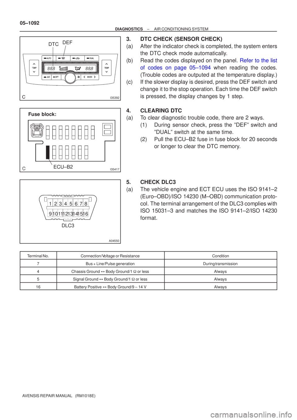
3.DTC CHECK (SENSOR CHECK)
(a)After the indicator check is completed, the system enters the DTC check mode automatically.
(b)Read the codes displayed on the panel. Refer to the list of codes on page 05±1094 when reading the codes.
(Trouble codes are outputed at the temperature display.)
(c) If the slower display is desired, press the DEF switch and
change it to the stop operation. Each time the DEF switch
is pressed, the display changes by 1 step.
4. CLEARING DTC
(a) To clear diagnostic trouble code, there are 2 ways. (1) During sensor check, press the ºDEFº switch andºDUALº switch at the same time.
(2) Pull the ECU±B2 fuse in fuse block for 20 seconds or longer to clear the DTC memory.
5. CHECK DLC3
(a) The vehicle engine and ECT ECU uses the ISO 9141±2 (Euro±OBD)/ISO 14230 (M±OBD) communication proto-
col. The terminal arrangement of the DLC3 complies with
ISO 15031±3 and matches the ISO 9141±2/ISO 14230
format.
Terminal No.Connection/Voltage or ResistanceCondition
7Bus + Line/Pulse generationDuring transmission
4Chassis Ground � Body Ground/1 � or lessAlways
5Signal Ground � Body Ground/1 � or lessAlways
16Battery Positive � Body Ground/9 ± 14 VAlways
Page 1126 of 5135

F44862
Engine Room R/B No.1 and Engine Room J/B No.1Power Steering
ECU Assy
Engine Room R/B No.4 EMPS Relay
W±R
FL MAIN
BatteryPIG
RLY
PGND R
R
RIE1L
1 1 1
1
1
1A
1 22 1
1
EMPS 53
51
E14
3
E15
2
E14 W±R
W±B
B±G
4B1
4A1
IM B±G 05±1076
± DIAGNOSTICSELECTRONIC MOTOR POWER STEERING SYSTEM
AVENSIS REPAIR MANUAL (RM1018E)
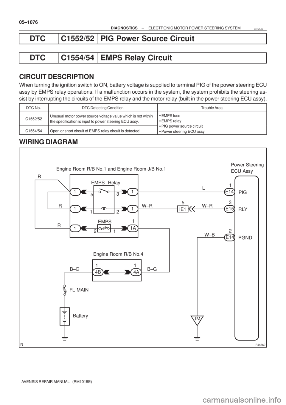
DTC C1552/52 PIG Power Source Circuit
DTC C1554/54 EMPS Relay Circuit
CIRCUIT DESCRIPTION
When turning the ignition switch to ON, battery voltage is supplied to terminal PIG of the power steering ECU
assy by EMPS relay operations. If a malfunction occurs in the system, the system prohibits the steering as-
sist by interrupting the circuits of the EMPS relay and the motor relay (built in the power steering ECU assy).
DTC No.DTC Detecting ConditionTrouble Area
C1552/52Unusual motor power source voltage value which is not within
the specification is input to power steering ECU assy.�EMPS fuse
�EMPS relay
�PIG power source circuitC1554/54Open or short circuit of EMPS relay circuit is detected.�PIG power source circuit
�Power steering ECU assy
WIRING DIAGRAM
0579O±02
Page 1127 of 5135
F44852
Engine Room R/B No.1 and
Engine Room J/B No.1:
EMPS
Fuse
EMPS Relay
± DIAGNOSTICSELECTRONIC MOTOR POWER STEERING SYSTEM
05±1077
AVENSIS REPAIR MANUAL (RM1018E)
INSPECTION PROCEDURE
NOTICE:
When performing the inspection of power steering ECU, ECU must be installed to the vehicle or fully
fixed.
1 INSPECT FUSE(EMPS)
(a) Remove the EMPS fuse from the engine room R/B No.1
and J/B No.1.
(b) Check the continuity of the EMPS fuse.
Standard:
Continuity
NG INSPECT FOR SHORT CIRCUIT IN HARNESS
AND ALL COMPONENTS CONNECTED TO
EMPS FUSE
OK
Page 1130 of 5135
F44867
Engine Room R/B No. 4 I13
Ignition SWDriver Side J/B
ECU±IG
AM1
ALT
FL MAIN
BatteryIG1Relay
AM1 IG1IG
PGND R±W
R±WR±W
W±B
W±B
W±B B±G B±GG±Y
G±RJ10G
J20C
J11G
J21C
E156
E142 DB 18
DH5
DH1
DN1 DA9
4B1
4D1
IJ IM 12125 3
31J/C
(*1)
(*2)(*1)
(*2)
*1: LHD
*2: RHDPower Steering
ECU Assy
± DIAGNOSTICSELECTRONIC MOTOR POWER STEERING SYSTEM
05±1073
AVENSIS REPAIR MANUAL (RM1018E)
DTC C1551/51 IG Power Source Circuit Malfunction
CIRCUIT DESCRIPTION
The power steering ECU assy identifies ON or OFF status of the ignition switch by this circuit.
DTC No.DTC Detecting ConditionTrouble Area
C1551/51Unusual IG voltage value which exceeds the specification is
inputed to power steering ECU assy.
�ECU±IG fuse
�IG power source circuit
�Charging system
�Power steering ECU assy
WIRING DIAGRAM
0579N±02
Page 1131 of 5135
F44856
ECU±IG
Fuse Driver Side J/B:
F44851
PGND (±)
E14
05±1074
± DIAGNOSTICSELECTRONIC MOTOR POWER STEERING SYSTEM
AVENSIS REPAIR MANUAL (RM1018E)
INSPECTION PROCEDURE
NOTICE:
When performing the inspection of power steering ECU, ECU must be installed to the vehicle or fully
fixed.
1 INSPECT FUSE(ECU±IG)
(a) Remove the ECU±IG fuse from the driver side J/B.
(b) Check the continuity of the ECU±IG fuse.
Standard:
Continuity
NG INSPECT FOR SHORT CIRCUIT IN ALL
HARNESS AND COMPONENTS CONNECTED
TO ECU±IG FUSE
OK
2 CHECK HARNESS AND CONNECTOR(POWER STEERING ECU ASSY ± BODY
GROUND)
(a) Disconnect the E14 connector from the power steering
ECU assy.
(b) Measure the resistance between terminal PGND of E14
connector and body ground.
Standard:
Resistance: 1 � or less
NG REPAIR OR REPLACE HARNESS OR
CONNECTOR
OK