Page 13 of 5135
Abbreviations Meaning
H±FUSEHigh Current Fuse
HIHigh
HIDHigh Intensity Discharge (Head Lamp)
HSGHousing
HTHard Top
HWSHeated Windshield Sy")
± INTRODUCTIONTERMS
01±39
AVENSIS REPAIR MANUAL (RM1018E)Abbreviations Meaning
H±FUSEHigh Current Fuse
HIHigh
HIDHigh Intensity Discharge (Head Lamp)
HSGHousing
HTHard Top
HWSHeated Windshield System
ICIntegrated Circuit
IDIIndirect Diesel Injection
IFSIndependent Front Suspension
IGIgnition
IIAIntegrated Ignition Assembly
INIntake (Manifold, Valve)
INTIntermittent
I/PInstrument Panel
IRSIndependent Rear Suspension
ISCIdle Speed Control
J/BJunction Block
J/CJunction Connector
KDKick±Down
LANLocal Area Network
LBLiftback
LCDLiquid Crystal Display
LEDLight Emitting Diode
LHLeft±Hand
LHDLeft±Hand Drive
L/H/WLength, Height, Width
LLCLong±Life Coolant
LNGLiquified Natural Gas
LOLow
LPGLiquified Petroleum Gas
LSDLimited Slip Differential
LSP & PVLoad Sensing Proportioning And Bypass Valve
LSPVLoad Sensing Proportioning Valve
MAPManifold Absolute Pressure
MAX.Maximum
MICMicrophone
MILMalfunction Indicator Lamp
MIN.Minimum
MG1Motor Generator No.1
MG2Motor Generator No.2
MPMultipurpose
MPIMultipoint Electronic Injection
MPXMultiplex Communication System
M/T, MTMManual Transmission (Transaxle)
MTMount
MTGMounting
NNeutral
NANatural Aspiration
No.Number
O2SOxygen Sensor
O/DOverdrive
Page 1473 of 5135

RADIO BROADCAST CANNOT BE RECEIVED (BAD RECEPTION)
INSPECTION PROCEDURE
1 CHECK IF RADIO AUTO±SEARCH FUNCTIONS PROPERLY
(a) Check")
05±1420
± DIAGNOSTICSAUDIO SYSTEM
AVENSIS REPAIR MANUAL (RM1018E)
RADIO BROADCAST CANNOT BE RECEIVED (BAD RECEPTION)
INSPECTION PROCEDURE
1 CHECK IF RADIO AUTO±SEARCH FUNCTIONS PROPERLY
(a) Check if the radio auto±search functions properly.
(1) Perform the auto±search of the radio and check that it functions normally.
Standard: The radio auto±search functions properly.
OK REPLACE RADIO RECEIVER ASSY
NG
2 CHECK OPTIONAL COMPONENT
(a) Check optional component (Sun shade film, telephone antenna etc.).
(1) Check whether or not any optional component is installed, such as the sunshade film and the
telephone antenna.
Standard: Optional component is installed.
OK EFFECT FROM OPTIONAL COMPONENT
NG
3 CHECK ANTENNA FOR NOISE PRODUCTION
(a) Noise Check with Antenna.
(1) With the ignition switch in ACC, turn on the radio and choose the AM mode.
(2) Place a tip of a screwdriver or the antenna of the antenna assembly w/ holder and check that
the noise heard from the speaker.
Standard: Noise occurs.
OK REPLACE RADIO RECEIVER ASSY
NG
0549R±06
Page 1503 of 5135
05C3F±01
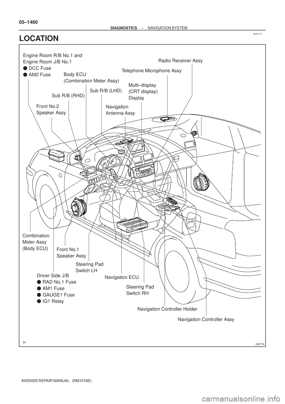
I34714
Driver Side J/B
� RAD No.1 Fuse
� AM1 Fuse
� GAUGE1 Fuse
� IG1 RelayFront No.1
Speaker AssyMulti±display
(CRT display)
Display
Steering Pad
Switch LH Engine Room R/B No.1 and
Engine Room J/B No.1
� DCC Fuse
� AM2 Fuse
Front No.2
Speaker Assy
Steering Pad
Switch RH Sub R/B (LHD)
Sub R/B (RHD)
Navigation
Antenna AssyTelephone Microphone AssyRadio Receiver Assy
Navigation Controller Assy Navigation Controller Holder Navigation ECU Combination
Meter Assy
(Body ECU)
Body ECU
(Combination Meter Assy)
05±1460
± DIAGNOSTICSNAVIGATION SYSTEM
AVENSIS REPAIR MANUAL (RM1018E)
LOCATION
Page 1539 of 5135
I35657
S15
Steering Pad Switch LH
Multi±display
(CRT Display) DisplayAU1
AU2
EAU12
11
10LG (*1)
P (*1)
W±R (*1)
GTX+
GTX±
CTX±
CTX+M1
M1
M2
M25
18
10
5P
LG
LG
V
T11
Telephone Microphone Assy
MACC
MIC+
MIC±5
4
2R
B
W
(Shielded)17
ID1
ID1
ID1
ID118
16
14R
B
W
(Shielded)Radio Receiver Assy
7
8
6 R7
R7
R7SW1
SW2
GND
TX+
TX± R6
R69
10
Navigation ECU
TX±
TX+
MACC
MIC+
MIC±
SGND N4
N4
N5
N5
N5
N54
3
5
6 BR
BR
*1: w/ Steering SW10
5 05±1494
± DIAGNOSTICSNAVIGATION SYSTEM
AVENSIS REPAIR MANUAL (RM1018E)
THE SYSTEM CANNOT BE OPERATED BY THE VOICE SOUND
WIRING DIAGRAM
05C3W±01
Page 1541 of 5135
I35670
MIC+
MACC MIC±
MACC MIC+ MIC±
Navigation ECU:
Telephone Microphone Assy:
T11
N5
05±1496
±
DIAGNOSTICS NAVIGATION SYSTEM
AVENSIS REPAIR MANUAL (RM1018E)
4CHECK HARNESS AND CONNECTOR(NAVIGATION ECU ± TELEPHONE MICROPHONE ASSY)
(a)Disconnect the connectors from the navigation ECU and
telephone microphone assy.
(1)Check continuity between the terminals at eachcondition, as shown in the chart.
Standard:
Tester connectionSpecified condition
MACC ± MACCContinuity
MIC+ ± MIC+Continuity
MIC± ± MIC±Continuity
(2)Check for a short between the terminals at each condition, as shown in the chart.
Standard:
Tester connectionSpecified condition
MACC ± Body groundNo continuity
MIC+ ± Body groundNo continuity
MIC± ± Body groundNo continuity
NGREPAIR OR REPLACE HARNESS OR CONNECTOR
OK
5REPLACE TELEPHONE MICROPHONE ASSY
Standard: Normally returns NGREPLACE NAVIGATION ECU (See page 67±27)
OK
SYSTEM OK
Page 3464 of 5135
Abbreviations Meaning
HIHigh
HIDHigh Intensity Discharge (Head Lamp)
HSGHousing
HTHard Top
HWSHeated Windshield System
ICIntegrated")
± INTRODUCTIONTERMS
01±9
1AZ±FSE ENGINE REPAIR MANUAL (RM1019E)Abbreviations Meaning
HIHigh
HIDHigh Intensity Discharge (Head Lamp)
HSGHousing
HTHard Top
HWSHeated Windshield System
ICIntegrated Circuit
IDIIndirect Diesel Injection
IFSIndependent Front Suspension
IGIgnition
IIAIntegrated Ignition Assembly
INIntake (Manifold, Valve)
INTIntermittent
I/PInstrument Panel
IRSIndependent Rear Suspension
ISCIdle Speed Control
J/BJunction Block
J/CJunction Connector
KDKick±Down
LANLocal Area Network
LBLiftback
LCDLiquid Crystal Display
LEDLight Emitting Diode
LHLeft±Hand
LHDLeft±Hand Drive
L/H/WLength, Height, Width
LLCLong±Life Coolant
LNGLiquified Natural Gas
LOLow
LPGLiquified Petroleum Gas
LSDLimited Slip Differential
LSP & PVLoad Sensing Proportioning And Bypass Valve
LSPVLoad Sensing Proportioning Valve
MAPManifold Absolute Pressure
MAX.Maximum
MICMicrophone
MILMalfunction Indicator Lamp
MIN.Minimum
MG1Motor Generator No.1
MG2Motor Generator No.2
MPMultipurpose
MPIMultipoint Electronic Injection
MPXMultiplex Communication System
M/T, MTMManual Transmission (Transaxle)
MTMount
MTGMounting
NNeutral
NANatural Aspiration
No.Number
O2SOxygen Sensor
O/DOverdrive
OEMOriginal Equipment Manufacturing
 DisplayAU1
AU2
EAU12
11
10LG (*1)
P (*1)
W±R (*1)
GTX+
GTX±
CTX±
CTX+M1
M1
M2
M25
18
10
5P
LG
LG
V
T11
Telephone Microphone Assy
MACC")

4CHECK HARNESS AND CONNECTOR(NAVIGA")