Page 1732 of 5135
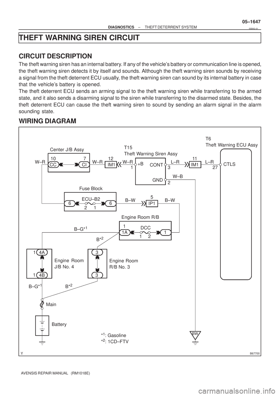
B67700
CTLS
27 L±R
IM111 T15
Theft Warning Siren Assy
W±R
CI CC7
2
2
4AECU±B2 Fuse Block 10
1 W±R
B*
2
Battery Center J/B Assy
6T6
Theft Warning ECU Assy
BW
+B
3 W±R
B±G*
1
L±R
IM112
GND CONT
6
IP15
B±W B±W
Engine Room R/B
DCC
1 21
1 1A
B*
2B±G*1
4B
Main3
3 11W±B
*
1: Gasoline
*2: 1CD±FTV1
Engine Room
R/B No. 3 Engine Room
J/B No. 4
± DIAGNOSTICSTHEFT DETERRENT SYSTEM
05±1647
AVENSIS REPAIR MANUAL (RM1018E)
THEFT WARNING SIREN CIRCUIT
CIRCUIT DESCRIPTION
The theft warning siren has an internal battery. If any of the vehicle's battery or communication line is opened,
the theft warning siren detects it by itself and sounds. Although the theft warning siren sounds by receiving
a signal from the theft deterrent ECU usually, the theft warning siren can sound by its internal battery in case
that the vehicle's battery is opened.
The theft deterrent ECU sends an arming signal to the theft warning siren while transferring to the armed
state, and it also sends a disarming signal to the siren while transferring to the disarmed state. Besides, the
theft deterrent ECU can cause the theft warning siren to sound by sending an alarm signal in the alarm
sounding state.
WIRING DIAGRAM
05BAG±01
Page 1733 of 5135
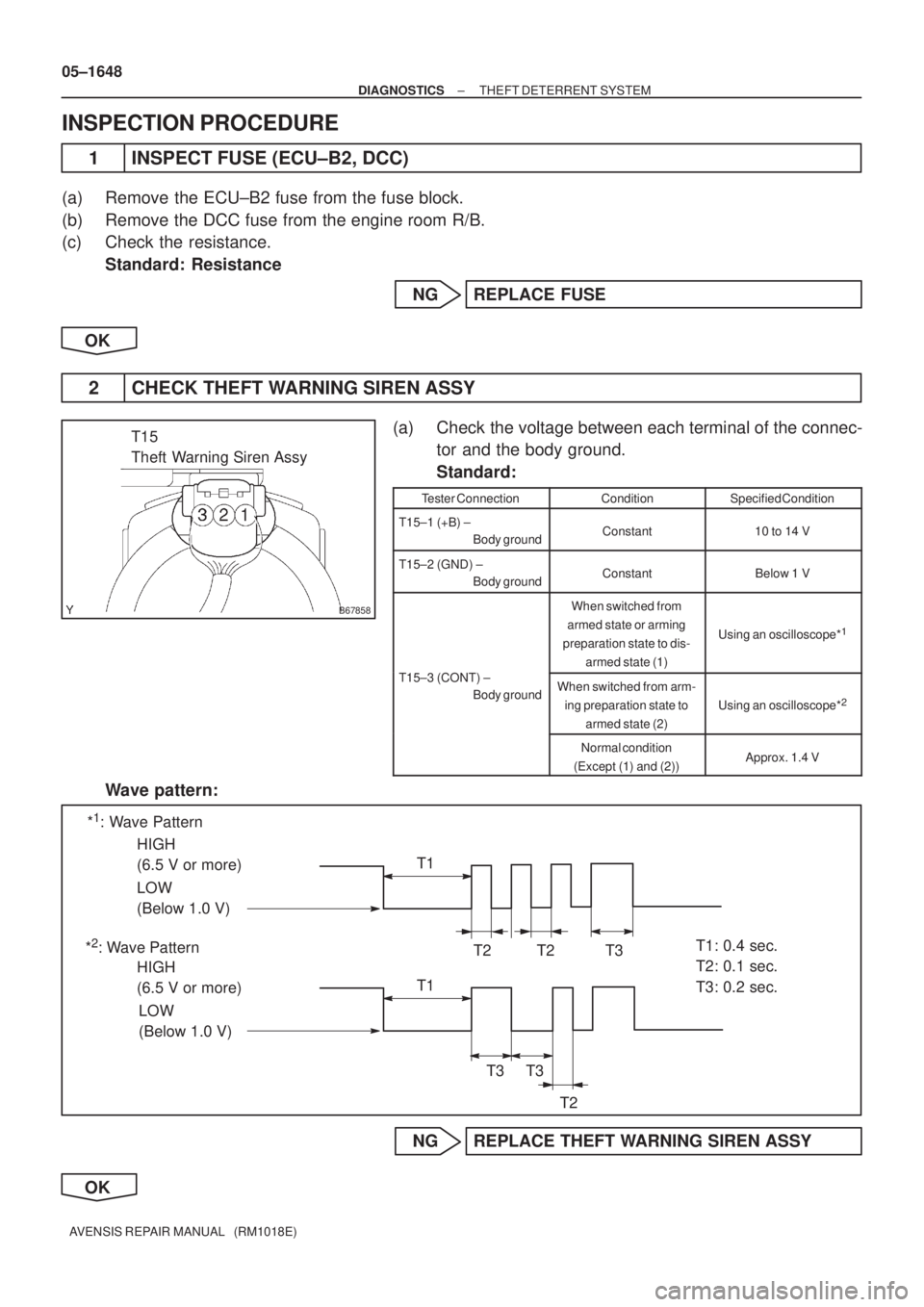
B67858
T15
Theft Warning Siren Assy
*1: Wave Pattern
*
2: Wave PatternHIGH
(6.5 V or more)
HIGH
(6.5 V or more) LOW
(Below 1.0 V)
LOW
(Below 1.0 V)T1: 0.4 sec.
T2: 0.1 sec.
T3: 0.2 sec. T1
T2
T3
T1
T3T3
T2
T2
05±1648
± DIAGNOSTICSTHEFT DETERRENT SYSTEM
AVENSIS REPAIR MANUAL (RM1018E)
INSPECTION PROCEDURE
1 INSPECT FUSE (ECU±B2, DCC)
(a) Remove the ECU±B2 fuse from the fuse block.
(b) Remove the DCC fuse from the engine room R/B.
(c) Check the resistance.
Standard: Resistance
NG REPLACE FUSE
OK
2 CHECK THEFT WARNING SIREN ASSY
(a) Check the voltage between each terminal of the connec-
tor and the body ground.
Standard:
Tester ConnectionConditionSpecified Condition
T15±1 (+B) ±
Body groundConstant10 to 14 V
T15±2 (GND) ±
Body groundConstantBelow 1 V
When switched from
armed state or arming
preparation state to dis-
armed state (1)
Using an oscilloscope*1
T15±3 (CONT) ±
Body groundWhen switched from arm-
ing preparation state to
armed state (2)
Using an oscilloscope*2
Normal condition
(Except (1) and (2))Approx. 1.4 V
Wave pattern:
NG REPLACE THEFT WARNING SIREN ASSY
OK
Page 1736 of 5135
B67416
B68374
21
5
3
± DIAGNOSTICSTHEFT DETERRENT SYSTEM
05±1645
AVENSIS REPAIR MANUAL (RM1018E)
INSPECTION PROCEDURE
1 INSPECT FUSE (HORN)
(a) Remove the HORN fuse from the engine room R/B.
(b) Check the resistance.
Standard: Resistance
NG REPLACE FUSE
OK
2 INSPECT HORN ASSY (LOW PITCED, HIGH PITCHED)
(a) Check operation of the horn.
Standard:
Measurement ConditionSpecified Condition
Battery positive (+) � Terminal 1
Battery negative (±) � Horn bodyHorn blows
NG REPAIR OR REPLACE HORN ASSY
OK
3 INSPECT RELAY (HORN)
(a) Remove the HORN relay from the engine room R/B No.
2.
(b) Check operation of the HORN relay.
Standard:
Tester ConnectionSpecified Condition
10 k�or higher
3 ± 5Below 1 �
(When battery voltage is applied to terminals 1 and 2)
NG REPLACE RELAY
OK
Page 1758 of 5135
± DIAGNOSTICSCRUISE CONTROL SYSTEM
05±1711
AVENSIS REPAIR MANUAL (RM1018E)
DTC P0571/52 BRAKE SWITCH ºAº CIRCUIT
CIRCUIT DESCRIPTION
When the brake pedal is depressed, the stop lamp switch assy sends a signal to the ECM. When the ECM
receives this signal, it cancels the cruise control.
A fail±safe function is provided so that it functions normally, even if there is a malfunction in the stop lamp
signal circuit.
The cancel condition occurs when battery positive voltage is supplied to terminal STP.
When the brake is on, battery positive voltage is normally applied through the STOP fuse and the stop lamp
switch assy to terminal STP of the ECM, and the ECM turns the cruise control OFF.
If the harness connected to terminal STP has an open circuit, terminal STP will have battery positive voltage
and the cruise control will be turned OFF.
DTC No.DTC Detection ConditionTrouble Area
P0571/52
The malfunction code is output when the voltage of the STP
terminal and that of the ST1 terminal on the ECM are less than
1 V for 0.5 sec. or more.
When the following conditions are realized, a malfunction is
detected.
�The STP terminal voltage is less than 1 V.
�The ST1 terminal voltage is less than 1 V.
�For more than 0.5 sec. or more.
�Stop lamp switch assy
�Stop lamp switch assy circuit
�ECM
05C4R±01
Page 1773 of 5135
I35838
(1)
(3)
I35839
(3)
(1)
± DIAGNOSTICSCRUISE CONTROL SYSTEM
05±1703
AVENSIS REPAIR MANUAL (RM1018E)STP LIGHT SW1 S
Stop light SW signal (Sub CPU) /
ON or OFFON : Brake pedal depressed
OFF : Brake pedal released±
SHIFT D POSPNP SW signal (D position) / ON
or OFFON : Shift D position
OFF : Except shift D position±
HINT:
º3º is OK but º1º is NG � ECM failure
º1º is OK but º2º is NG � DTC output or ECM failure
º3º is OK but cruise indicator does not turn on � CRUISE MAIN indicator or wire harness or ECM failure
4. DTC CLEAR
(a) The following methods will erase the DTCs and freeze frame data.
(1) The hand±held tester can be used to erase the codes.
(2) Disconnecting the battery terminals or EFI No.1 fuse can also erase the codes (1AZ±FSE).
Disconnecting the battery terminals or EFI the fuse (1CD±FTV).
(b) After completing repairs, the DTC retained in the memory can be cleared by removing the EFI No.1
fuse for 1 minute or more with the ignition switch to the OFF position.
(c) Check that the normal code is displayed after connecting the fuse.
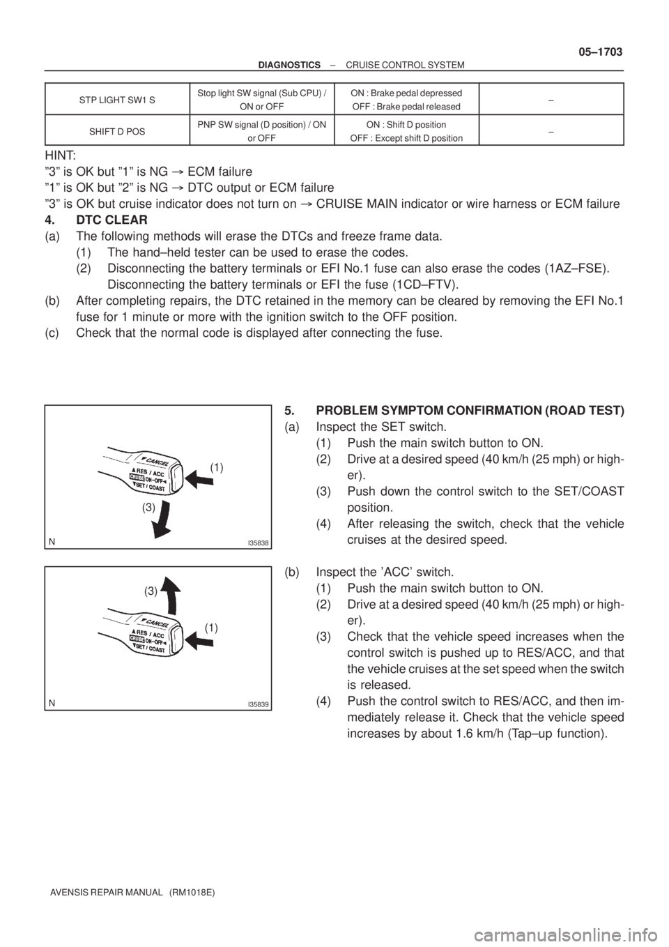
5. PROBLEM SYMPTOM CONFIRMATION (ROAD TEST)
(a) Inspect the SET switch.
(1) Push the main switch button to ON.
(2) Drive at a desired speed (40 km/h (25 mph) or high-
er).
(3) Push down the control switch to the SET/COAST
position.
(4) After releasing the switch, check that the vehicle
cruises at the desired speed.
(b) Inspect the 'ACC' switch.
(1) Push the main switch button to ON.
(2) Drive at a desired speed (40 km/h (25 mph) or high-
er).
(3) Check that the vehicle speed increases when the
control switch is pushed up to RES/ACC, and that
the vehicle cruises at the set speed when the switch
is released.
(4) Push the control switch to RES/ACC, and then im-
mediately release it. Check that the vehicle speed
increases by about 1.6 km/h (Tap±up function).
Page 1779 of 5135
B67809
Battery113
31 MPX1P
Theft Warning ECU Assy
E10 18
H 22
J/C
+B
W±B*
5
T6 I14
MainW±R*
5
AIC1BEAN
(EFI)
B*
3
POWER
EARTH
3
Instrument Panel J/B Assy
(Integration Relay)
ECMCombination Meter Assy
(Combination Meter ECU)
E9 E923 20
C10
BEAN
(BODY) 14
C10 P±B P±B
BEAN
(SECURITY) 15
C10 P±L*
4
MPX2
MPX
20
C11
C1017 J11 J26 J10
J26F F
F
W±R*
6
W±R
6
6
12DOME
B±W IE4
IP14*
5
5*6
B±W
1
1 2
1A
B±G*
1,
2
B±G*1,
2B*3
3
1
1 4B 4A
W±B*6
A
J16
J/CJ17
J/C
IK
IO*
1,
2,
5
*1: 1AZ±FSE
*2: 1AZ±FE, 1ZZ±FE, 3ZZ±FE
*
3: 1CD±FTV
*
4: w/ Theft Deterrent System
*5: LHD
*
6: RHD *
1*2*3
Engine Room R/BFuse Block Assy
Engine Room J/B No. 4*1,
2Engine Room R/B No. 3*3
DCC
1
AA
W±B*
6
W±BA
J15
J/C
IL*
3,
5
05±1694
± DIAGNOSTICSMULTIPLEX COMMUNICATION SYSTEM
AVENSIS REPAIR MANUAL (RM1018E)
WIRING DIAGRAM
Page 2344 of 5135
1600R±13
± COOLINGCOOLING FAN SYSTEM (1AZ±FE)
16±17
AVENSIS REPAIR MANUAL (RM1018E)
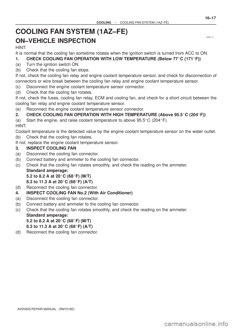
COOLING FAN SYSTEM (1AZ±FE)
ON±VEHICLE INSPECTION
HINT:
It is normal that the cooling fan sometime rotates when the ignition switch is turned from ACC to ON.
1. CHECK COOLING FAN OPERATION WITH LOW TEMPERATURE (Below 77�C (171�F))
(a) Turn the ignition switch ON.
(b) Check that the cooling fan stops.
If not, check the cooling fan relay and engine coolant temperature sensor, and check for disconnection of
connectors or wire break between the cooling fan relay and engine coolant temperature sensor.
(c) Disconnect the engine coolant temperature sensor connector.
(d) Check that the cooling fan rotates.
If not, check the fuses, cooling fan relay, ECM and cooling fan, and check for a short circuit between the
cooling fan relay and engine coolant temperature sensor.
(e) Reconnect the engine coolant temperature sensor connector.
2. CHECK COOLING FAN OPERATION WITH HIGH TEMPERATURE (Above 95.5�C (204�F))
(a) Start the engine, and raise coolant temperature to above 95.5�C (204�F).
HINT:
Coolant temperature is the detected value by the engine coolant temperature sensor on the water outlet.
(b) Check that the cooling fan rotates.
If not, replace the engine coolant temperature sensor.
3. INSPECT COOLING FAN
(a) Disconnect the cooling fan connector.
(b) Connect battery and ammeter to the cooling fan connector.
(c) Check that the cooling fan rotates smoothly, and check the reading on the ammeter.
Standard amperage:
5.2 to 8.2 A at 20�C (68�F) (M/T)
8.3 to 11.3 A at 20�C (68�F) (A/T)
(d) Reconnect the cooling fan connector.
4. INSPECT COOLING FAN No.2 (With Air Conditioner)
(a) Disconnect the cooling fan connector.
(b) Connect battery and ammeter to the cooling fan connector.
(c) Check that the cooling fan rotates smoothly, and check the reading on the ammeter.
Standard amperage:
5.2 to 8.2 A at 20�C (68�F) (M/T)
8.3 to 11.3 A at 20�C (68�F) (A/T)
(d) Reconnect the cooling fan connector.
Page 2356 of 5135
1600R±14
± COOLINGCOOLING FAN SYSTEM (1ZZ±FE/3ZZ±FE)
16±5
AVENSIS REPAIR MANUAL (RM1018E)
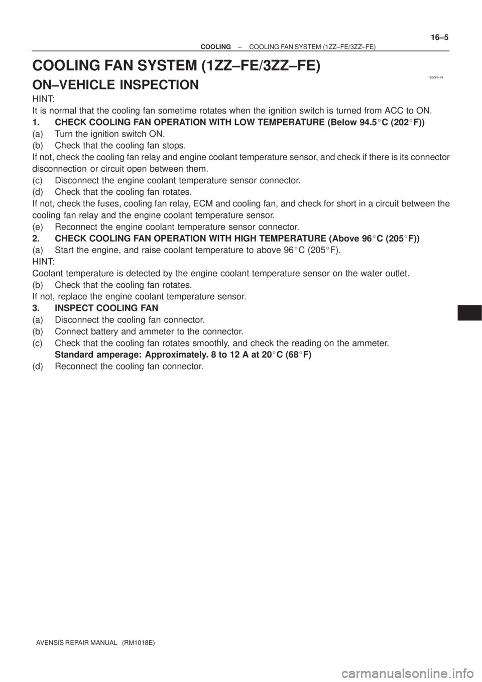
COOLING FAN SYSTEM (1ZZ±FE/3ZZ±FE)
ON±VEHICLE INSPECTION
HINT:
It is normal that the cooling fan sometime rotates when the ignition switch is turned from ACC to ON.
1. CHECK COOLING FAN OPERATION WITH LOW TEMPERATURE (Below 94.5�C (202�F))
(a) Turn the ignition switch ON.
(b) Check that the cooling fan stops.
If not, check the cooling fan relay and engine coolant temperature sensor, and check if there is its connector
disconnection or circuit open between them.
(c) Disconnect the engine coolant temperature sensor connector.
(d) Check that the cooling fan rotates.
If not, check the fuses, cooling fan relay, ECM and cooling fan, and check for short in a circuit between the
cooling fan relay and the engine coolant temperature sensor.
(e) Reconnect the engine coolant temperature sensor connector.
2. CHECK COOLING FAN OPERATION WITH HIGH TEMPERATURE (Above 96�C (205�F))
(a) Start the engine, and raise coolant temperature to above 96�C (205�F).
HINT:
Coolant temperature is detected by the engine coolant temperature sensor on the water outlet.
(b) Check that the cooling fan rotates.
If not, replace the engine coolant temperature sensor.
3. INSPECT COOLING FAN
(a) Disconnect the cooling fan connector.
(b) Connect battery and ammeter to the connector.
(c) Check that the cooling fan rotates smoothly, and check the reading on the ammeter.
Standard amperage: Approximately. 8 to 12 A at 20�C (68�F)
(d) Reconnect the cooling fan connector.