Page 2481 of 5135

190NW±01
A81052
������������A82936
Type A
Type B
BlueWhite
Red Green DarkClear or
light yellow
B00543
± STARTING & CHARGINGCHARGING SYSTEM (1AZ±FE)
19±15
AVENSIS REPAIR MANUAL (RM1018E)
ON±VEHICLE INSPECTION
1. CHECK BATTERY ELECTROLYTE LEVEL
(a) Check the electrolyte quantity of each cell.
(1) If the electrolyte is under the low level, replace the battery (or add distilled water if possible) and
check the charging system.
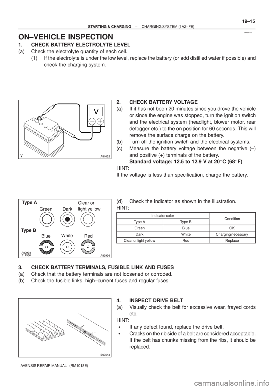
2. CHECK BATTERY VOLTAGE
(a) If it has not been 20 minutes since you drove the vehicle
or since the engine was stopped, turn the ignition switch
and the electrical system (headlight, blower motor, rear
defogger etc.) to the on position for 60 seconds. This will
remove the surface charge on the battery.
(b) Turn off the ignition switch and the electrical systems.
(c) Measure the battery voltage between the negative (±)
and positive (+) terminals of the battery.
Standard voltage: 12.5 to 12.9 V at 20�C (68�F)
HINT:
If the voltage is less than specification, charge the battery.
(d) Check the indicator as shown in the illustration.
HINT:
Indicator colorConditionType AType BCondition
GreenBlueOK
DarkWhiteCharging necessary
Clear or light yellowRedReplace
3. CHECK BATTERY TERMINALS, FUSIBLE LINK AND FUSES
(a) Check that the battery terminals are not loosened or corroded.
(b) Check the fusible links, high±current fuses and regular fuses.
4. INSPECT DRIVE BELT
(a) Visually check the belt for excessive wear, frayed cords
etc.
HINT:
�If any defect found, replace the drive belt.
�Cracks on the rib side of a belt are considered acceptable.
If the belt has chunks missing from the ribs, it should be
replaced.
Page 2483 of 5135
190NV±01
19±14
± STARTING & CHARGINGCHARGING SYSTEM (1AZ±FE)
AVENSIS REPAIR MANUAL (RM1018E)
CHARGING SYSTEM (1AZ±FE)
PRECAUTION
1. Check that the battery cables are connected to the correct terminals.
2. Disconnect the battery cables when the battery is given a quick charge.
3. Do not perform tests with a high voltage insulation resistance tester.
4. Never disconnect the battery while the engine is running.
5. Check that the charging cable is tightened on terminal B of the generator and the fuse box.
Page 2921 of 5135
I35431
Burner Motor
Glow Plug
Surface Sensor
Temp. Control Sensor
Flame Sensor13
Power
Heater
ECU
Connector BTerminal L
of AlternatorBattery
Metering Pump
Fuse (20 A)
Vehicle Side SW 14
9
12
5
6
3
4
1
2R
BR
B±R
G
L±Y
L
Y
L±W5
1
6
2
7
3
8
4W±B
R±G
R±B Connector A
IG
W±R (*1)
Y±R (*2)
R±L (*1)
R±Y (*2)
*1: TMC Made
*2: TMUK Made 55±16
± HEATER & AIR CONDITIONERCOMBUSTION TYPE POWER HEATER SYSTEM
AVENSIS REPAIR MANUAL (RM1018E)
2. DESCRIPTION OF DISPLAY AND BUTTONS
(a) AF: Current Value Malfunction (Blinking at current failure)
Diag: DTC (Example: 064 Flame sensor break)
Memory Clear button: Deletion of faulty memory (Press both buttons together for longer than 2 se-
conds)
> Button: Scroll up of faulty memory (The past 5 codes can be stored.)
< Button: Scroll down of faulty memory (The past 5 codes can be stored.)
3. FAULTY MEMORY
(a) The ECU is able to store up to 5 pieces of faulty memory. If it is full, the new data is written over F5.
4. WIRING DIAGRAM
Page 2925 of 5135
550ZE±01
±
HEATER & AIR CONDITIONER ELECTRICAL TYPE POWER HEATER SYSTEM
55±13
AVENSIS REPAIR MANUAL (RM1018E)
ELECTRICAL TYPE POWER HEATER SYSTEM
PROBLEM SYMPTOMS TABLE
Use the table below to help you find the cause of the problem. The numbers \
indicate the priority of the likely
cause of the problem. Check each part in order. If necessary, replace these parts.
SymptomSuspect AreaSee page
PTC heater does not operate, when perform in these conditions:
�Engine coolant temp.: 70 �C (158 �F) or below
� Engine speed: 650 rpm or above
� Temperature control selector: MAX. HOT
� Ambient temperature: Below 10 �C (50 �F)
1. HTR1 Fuse
2. HTR2 Fuse
3. HTR1 relay
4. HTR2 relay
5. PTC heater
6. ECM
7. Wire harness±
±
±
±
55±14
±
±
Page 2932 of 5135

550RQ±02
55±6
±
HEATER & AIR CONDITIONER AIR CONDITIONING SYSTEM
AVENSIS REPAIR MANUAL (RM1018E)
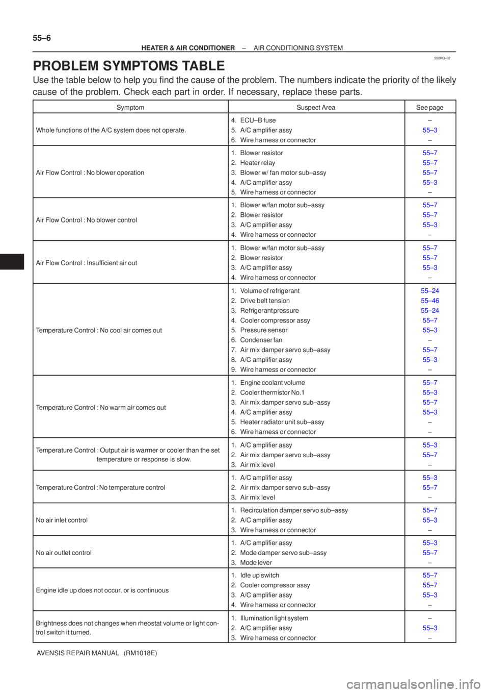
PROBLEM SYMPTOMS TABLE
Use the table below to help you find the cause of the problem. The numbers \
indicate the priority of the likely
cause of the problem. Check each part in order. If necessary, replace these parts.
SymptomSuspect AreaSee page
Whole functions of the A/C system does not operate.
4. ECU±B fuse
5. A/C amplifier assy
6. Wire harness or connector±
55±3 ±
Air Flow Control : No blower operation
1. Blower resistor
2. Heater relay
3. Blower w/ fan motor sub±assy
4. A/C amplifier assy
5. Wire harness or connector55±7
55±7
55±7
55±3±
Air Flow Control : No blower control
1. Blower w/fan motor sub±assy
2. Blower resistor
3. A/C amplifier assy
4. Wire harness or connector55±7
55±7
55±3
±
Air Flow Control : Insufficient air out
1. Blower w/fan motor sub±assy
2. Blower resistor
3. A/C amplifier assy
4. Wire harness or connector55±7
55±7
55±3±
Temperature Control : No cool air comes out
1. Volume of refrigerant
2. Drive belt tension
3. Refrigerant pressure
4. Cooler compressor assy
5. Pressure sensor
6. Condenser fan
7. Air mix damper servo sub±assy
8. A/C amplifier assy
9. Wire harness or connector55±24
55±46
55±2455±7
55±3 ±
55±7
55±3 ±
Temperature Control : No warm air comes out
1. Engine coolant volume
2. Cooler thermistor No.1
3. Air mix damper servo sub±assy
4. A/C amplifier assy
5. Heater radiator unit sub±assy
6. Wire harness or connector55±7
55±3
55±7
55±3±
±
Temperature Control : Output air is warmer or cooler than the set
temperature or response is slow.1. A/C amplifier assy
2. Air mix damper servo sub±assy
3. Air mix level55±3
55±7
±
Temperature Control : No temperature control
1. A/C amplifier assy
2. Air mix damper servo sub±assy
3. Air mix level55±3
55±7±
No air inlet control
1. Recirculation damper servo sub±assy
2. A/C amplifier assy
3. Wire harness or connector55±7
55±3±
No air outlet control
1. A/C amplifier assy
2. Mode damper servo sub±assy
3. Mode lever55±3
55±7±
Engine idle up does not occur, or is continuous
1. Idle up switch
2. Cooler compressor assy
3. A/C amplifier assy
4. Wire harness or connector55±7
55±7
55±3±
Brightness does not changes when rheostat volume or light con-
trol switch it turned.1. Illumination light system
2. A/C amplifier assy
3. Wire harness or connector±
55±3 ±
Page 3053 of 5135

650SQ±01
65±2
±
LIGHTING LIGHTING SYSTEM
AVENSIS REPAIR MANUAL (RM1018E)
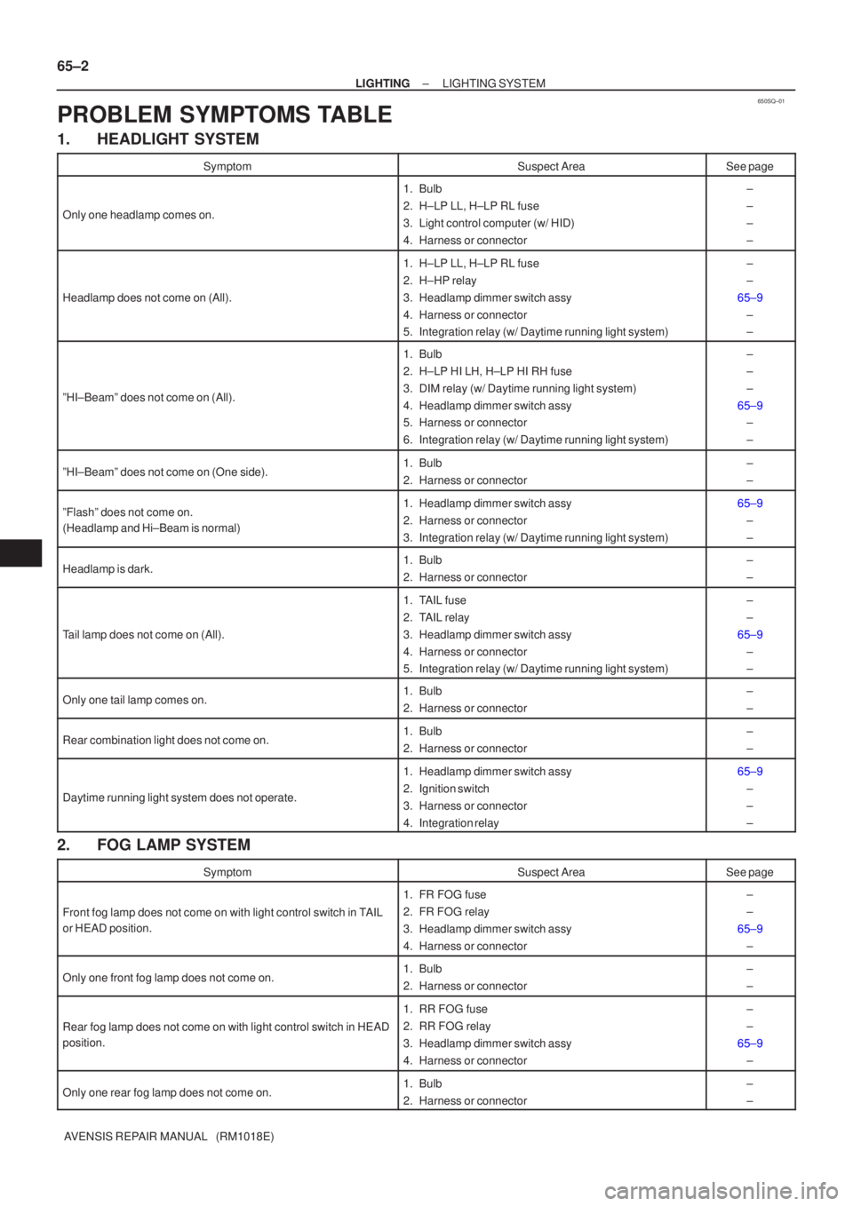
PROBLEM SYMPTOMS TABLE
1. HEADLIGHT SYSTEM
SymptomSuspect AreaSee page
Only one headlamp comes on.
1. Bulb
2. H±LP LL, H±LP RL fuse
3. Light control computer (w/ HID)
4. Harness or connector±
±
±
±
Headlamp does not come on (All).
1. H±LP LL, H±LP RL fuse
2. H±HP relay
3. Headlamp dimmer switch assy
4. Harness or connector
5. Integration relay (w/ Daytime running light system)±
±
65±9 ±
±
ºHI±Beamº does not come on (All).
1. Bulb
2. H±LP HI LH, H±LP HI RH fuse
3. DIM relay (w/ Daytime running light system)
4. Headlamp dimmer switch assy
5. Harness or connector
6. Integration relay (w/ Daytime running light system)±
±
±
65±9 ±
±
ºHI±Beamº does not come on (One side).1. Bulb
2. Harness or connector±
±
ºFlashº does not come on.
(Headlamp and Hi±Beam is normal)1. Headlamp dimmer switch assy
2. Harness or connector
3. Integration relay (w/ Daytime running light system)65±9
±
±
Headlamp is dark.1. Bulb
2. Harness or connector±
±
Tail lamp does not come on (All).
1. TAIL fuse
2. TAIL relay
3. Headlamp dimmer switch assy
4. Harness or connector
5. Integration relay (w/ Daytime running light system)±
±
65±9 ±
±
Only one tail lamp comes on.1. Bulb
2. Harness or connector±
±
Rear combination light does not come on.1. Bulb
2. Harness or connector±
±
Daytime running light system does not operate.
1. Headlamp dimmer switch assy
2. Ignition switch
3. Harness or connector
4. Integration relay65±9±
±
±
2. FOG LAMP SYSTEM
SymptomSuspect AreaSee page
Front fog lamp does not come on with light control switch in TAIL
or HEAD position.
1. FR FOG fuse
2. FR FOG relay
3. Headlamp dimmer switch assy
4. Harness or connector±
±
65±9 ±
Only one front fog lamp does not come on.1. Bulb
2. Harness or connector±
±
Rear fog lamp does not come on with light control switch in HEAD
position.
1. RR FOG fuse
2. RR FOG relay
3. Headlamp dimmer switch assy
4. Harness or connector±
±
65±9 ±
Only one rear fog lamp does not come on.1. Bulb
2. Harness or connector±
±
Page 3054 of 5135

±
LIGHTING LIGHTING SYSTEM
65±3
AVENSIS REPAIR MANUAL (RM1018E)
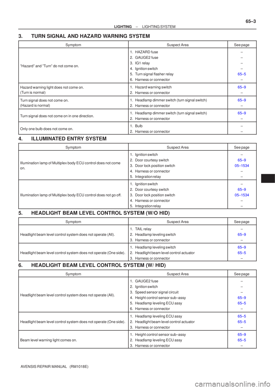
3. TURN SIGNAL AND HAZARD WARNING SYSTEM
SymptomSuspect AreaSee page
ºHazardº and ºTurnº do not come on.
1. HAZARD fuse
2. GAUGE2 fuse
3. IG1 relay
4. Ignition switch
5. Turn signal flasher relay
6. Harness or connector±
±
±
±
65±5
±
Hazard warning light does not come on.
(Turn is normal)1. Hazard warning switch
2. Harness or connector65±9±
Turn signal does not come on.
(Hazard is normal)1. Headlamp dimmer switch (turn signal switch)
2. Harness or connector65±9±
Turn signal does not come on in one direction.1. Headlamp dimmer switch (turn signal switch)
2. Harness or connector65±9±
Only one bulb does not come on.1. Bulb
2. Harness or connector±
±
4. ILLUMINATED ENTRY SYSTEM
SymptomSuspect AreaSee page
Illumination lamp of Multiplex body ECU control does not come
on.
1. Ignition switch
2. Door courtesy switch
3. Door lock position switch
4. Harness or connector
5. Integration relay±
65±9
05±1534 ±
±
Illumination lamp of Multiplex body ECU control does not go off.
1. Ignition switch
2. Door courtesy switch
3. Door lock position switch
4. Harness or connector
5. Integration relay±
65±9
05±1534 ±
±
5. HEADLIGHT BEAM LEVEL CONTROL SYSTEM (W/O HID)
SymptomSuspect AreaSee page
Headlight beam level control system does not operate (All).
1. TAIL relay
2. Headlamp leveling switch
3. Harness or connector±
65±9 ±
Headlight beam level control system does not operate (One side).
1. Headlamp leveling switch
2. Headlight beam level control actuator
3. Harness or connector65±9
65±5±
6. HEADLIGHT BEAM LEVEL CONTROL SYSTEM (W/ HID)
SymptomSuspect AreaSee page
Headlight beam level control system does not operate (All).
1. GAUGE2 fuse
2. Ignition switch
3. Speed sensor signal circuit
4. Height control sensor sub±assy
5. Headlamp leveling ECU assy
6. Harness or connector±
±
±
65±9
65±5 ±
Headlight beam level control system does not operate (One side).
1. Headlamp leveling ECU assy
2. Headlight beam level control actuator
3. Harness or connector65±5
65±5±
Beam level warning light comes on.
1. Height control sensor sub±assy
2. Headlamp leveling ECU assy
3. Harness or connector65±9
65±5±
Page 3055 of 5135
65±4
± LIGHTINGLIGHTING SYSTEM
AVENSIS REPAIR MANUAL (RM1018E)
7. OTHERS
SymptomSuspect AreaSee page
Vanity light does not operate.1. Bulb
2. Harness s or connector±
±
Instrument panel illumination does not operate (All).
1. TAIL relay
2. PANEL fuse
3. Harness or connector
4. Integration relay (w/ DRL)±
±
±
±
Stop light does not operate (All).
1. STOP fuse
2. Stop light switch
3. Harness or connector±
±
±
Back up lamp does not come on (All).
1. GAUGE fuse
2. IG1 relay
3. Back up lamp switch assy (M/T)
4. Park/neutral position switch (A/T)
5. Harness or connector±
±
±
±
±