Page 3294 of 5135
7408U±01
±
SLIDING ROOF/CONVERTIBLE SLIDING ROOF SYSTEM
74±5
AVENSIS REPAIR MANUAL (RM1018E)
PROBLEM SYMPTOMS TABLE
SymptomSuspected AreaSee Page
AUTO function does not operate1. Sliding roof motor assy74±3
Sliding roof system does not operate
1. S/ROOF fuse
2. GAUGE1 fuse
3. IG1 relay
4. Integration relay
5. Sliding roof housing assy
6. Sliding roof motor switch assy
7. Sliding roof motor assy
8. Wire harness±
±
±
±
74±15 74±6
74±3
74±3
Sliding roof system stops operation halfway
1. Sliding roof motor assy
2. Wire harness
3. Sliding roof housing assy74±3
74±3
74±15
Page 3298 of 5135
B67299
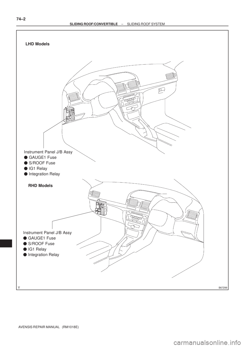
LHD Models
RHD Models
Instrument Panel J/B Assy
� GAUGE1 Fuse
� S/ROOF Fuse
� IG1 Relay
� Integration Relay
Instrument Panel J/B Assy
� GAUGE1 Fuse
� S/ROOF Fuse
� IG1 Relay
� Integration Relay
74±2
± SLIDING ROOF/CONVERTIBLESLIDING ROOF SYSTEM
AVENSIS REPAIR MANUAL (RM1018E)
Page 3305 of 5135
73094±02
±
THEFT DETERRENT & DOOR LOCK FUEL LID OPENER SYSTEM
73±29
AVENSIS REPAIR MANUAL (RM1018E)
PROBLEM SYMPTOMS TABLE
SymptomSuspected AreaSee Page
Fuel lid opener does not operate.
1. FUEL OPN fuse
2. Fuel lid opener switch
3. Fuel lid lock control assy
4. Wire harness68±1
73±30
73±30
Page 3463 of 5135
Abbreviations Meaning
DFLDeflector
DIFF.Differential
DIFF. LOCKDifferential Lock
D/INJDirect Injection
DLCData Link Connector
DLIDis")
01±8
± INTRODUCTIONTERMS
1AZ±FSE ENGINE REPAIR MANUAL (RM1019E)Abbreviations Meaning
DFLDeflector
DIFF.Differential
DIFF. LOCKDifferential Lock
D/INJDirect Injection
DLCData Link Connector
DLIDistributorless Ignition
DOHCDouble Overhead Camshaft
DPDash Pot
DSDead Soak
DSPDigital Signal Processor
DTCDiagnostic Trouble Code
DVDDigital Versatile Disc
EBDElectric Brake Force Distribution
ECAMEngine Control And Measurement System
ECDElectronic Controlled Diesel
ECDYEddy Current Dynamometer
ECTElectronic Control Transmission
ECUElectronic Control Unit
EDElectro±Deposited Coating
EDUElectronic Driving Unit
EDICElectric Diesel Injection Control
EFIElectronic Fuel Injection
E/GEngine
EGRExhaust Gas Recirculation
EGR±VMEGR±Vacuum Modulator
ELREmergency Locking Retractor
EMPSElectric Motor Power Steering
ENGEngine
ESAElectronic Spark Advance
ETCS±iElectronic Throttle Control System±intelligent
EVAPEvaporative Emission Control
EVPEvaporator
E±VRVElectric Vacuum Regulating Valve
EXExhaust
FEFuel Economy
FFFront±Engine Front±Wheel±Drive
F/GFuel Gauge
FIPGFormed In Place Gasket
FLFusible Link
F/PFuel Pump
FPUFuel Pressure Up
FrFront
F/WFlywheel
FW/DFlywheel Damper
FWDFront±Wheel±Drive
GASGasoline
GNDGround
GPSGlobal Positioning System
HACHigh Altitude Compensator
H/BHatchback
H±FUSEHigh Current Fuse
Page 3869 of 5135

05±9
AVENSIS REPAIR MANUAL (RM1018E)
2. DTC CHECK (Nomal Mode) :
NOTICE:
Hand±held tester only:
When the diagnosis system is s")
A76859
Hand±Held Tester
±
DIAGNOSTICS SFI SYSTEM (1ZZ±FE/3ZZ±FE)
05±9
AVENSIS REPAIR MANUAL (RM1018E)
2. DTC CHECK (Nomal Mode) :
NOTICE:
Hand±held tester only:
When the diagnosis system is switched from the normal
mode to the check (test) mode, it erases all DTCs and freeze
frame data recorded in the normal mode. So before switch-
ing modes, always check the DTCs and freeze frame data,
and then write them down.
(a) Checking DTCs using the hand±held tester.
(1) Connect the hand±held tester to the DLC3.
(2) Turn the ignition switch ON and switch the hand±
held tester main switch ON.
(3) Use the hand±held tester to check the DTCs and freeze frame data and then write them down. The
hand±held tester's instruction book.
(4)See page 05±16 to confirm the details of the DTCs.
(b) Clearing the DTCs using the hand±held tester: (1) Connect the hand±held tester to the DLC3.
(2) Turn the ignition switch ON.
(3) When operating hand±held tester to erase the
codes, the DTCs and freeze frame data will be
erased. (See the hand±held tester's instruction
book for operating instructions.)
(c) Clearing the DTCs not using the hand±held tester: (1) Disconnect the battery terminal or remove the EFIfuse for more than 60 seconds.
3. DTC CHECK (Check Mode):
HINT:
Hand±held tester only:
Compared to the normal mode, the check mode has more sens-
ing ability to detect malfunctions.
Furthermore, the same diagnostic items which are detected in
the normal mode can also be detected in the check (test) mode.
(a) Proceduce for check mode using hand±held tester.
(1) Check the initial conditions
�Battery positive voltage 11V or more.
�Throttle valve fully closed.
�Transmission in the ºPº or ºNº position.
�Air conditioning switched OFF.
(2) Turn the ignition switch OFF.
Page 3870 of 5135

AVENSIS REPAIR MANUAL (RM1018E)
(3) Connect the hand±held tester to the DLC3.
(4) Turn")
A76859
Hand±Held Tester
FI3605
ON
OFFBlinking
0.13 Second
05±10
± DIAGNOSTICSSFI SYSTEM (1ZZ±FE/3ZZ±FE)
AVENSIS REPAIR MANUAL (RM1018E)
(3) Connect the hand±held tester to the DLC3.
(4) Turn the ignition switch and the hand±held tester
main switch ON.
(5) Switch the hand±held tester from the normal mode
to the check (test) mode. The CHK ENG blinks in
0.13 sec interval as shown in the illustration.
NOTICE:
If the hand±held tester switches the ECM from the normal
mode to the check mode or vice±versa, or if the ignition
switch is turned from ON to ACC or OFF during the check
mode, the DTC and freeze frame data will be erased.
(6) Start the engine. (The CHK ENG lamp goes out af-
ter the engine start.)
(7) Simulate the conditions of the malfunction de-
scribed by the customer.
NOTICE:
Leave the ignition switch ON until you have checked the
DTC, etc.
(8) After simulating the malfunction conditions, use the
hand±held tester diagnosis selector to check the
DTCs and freeze frame data, etc.
HINT:
Be sure not to turn the ignition switch OFF, because the diagno-
sis system is changed from the check mode to the nomal mode
and will result in all of the DTCs and freeze frame data being
erased.
(9) After checking the DTCs, inspect the applicable cir-
cuit.
(b) Clearing the DTCs using the hand±held tester
(1) Connect the hand±held tester to DLC3.
(2) Turn the ignition switch ON.
(3) When operating hand±held tester to erase the
codes, the DTCs and freeze frame data will be
erased. (See the hand±held tester's instruction
book for operating instructions.)
(c) Clearing the DTCs not using the hand±held tester:
(1) Disconnect the battery terminal or remove the EFI
fuse for more than 60 seconds.
Page 3878 of 5135

05±175
AVENSIS REPAIR MANUAL (RM1018E)
2 PERFORM ACTIVE TEST BY HAND±HELD TESTER(OPERATION OF OCV)
(a) Connect the hand±held tester to the DLC3.
(b) Start the")
± DIAGNOSTICSSFI SYSTEM (1AZ±FE)
05±175
AVENSIS REPAIR MANUAL (RM1018E)
2 PERFORM ACTIVE TEST BY HAND±HELD TESTER(OPERATION OF OCV)
(a) Connect the hand±held tester to the DLC3.
(b) Start the engine and warm it up.
(c) Turn the ignition switch ON and push the hand±held tester main switch ON.
(d) Select the item ºDIAGNOSIS / OBD/MOBD / ACTIVE TEST / VVT CTRL B1º.
(e) Check the engine speed when operating the OCV by the hand±held tester.
Standard:
Tester operationSpecified condition
OCV is OFFNormal engine speed
OCV is ONRough idle or engine stall
OK Go to step 4
NG
3 READ OUTPUT DTC(CHECK IF DTC OUTPUT RECURS)
(a) Clear the DTC.
(1) Operating the hand±held tester to erase the codes, or disconnecting the battery terminal or the
EFI and ECTS fuses for more than 60 sec.
(b) Start and warm up the engine.
(c) Drive the vehicle around for 10 minutes or more.
(d) Read output DTC using the hand±held tester.
Standard: No DTC output.
HINT:
*: DTCs P0011/59 or P0012/59 is output when a foreign object in engine oil is caught in some part of the
system. These codes will stay registered even if the system returns to normal after a short time. These for-
eign objects are then captured by the oil filter, thus eliminating the source of the problem.
OK VVT SYSTEM OK*
NG
Page 3880 of 5135

05±177
AVENSIS REPAIR MANUAL (RM1018E)
9REPLACE CAMSHAFT TIMING GEAR ASSY
GO
10CHECK FOR BLOCKAGE(OCV, OIL CHECK VALVE AND OIL HOLE)
NGREPAIR OR REPLACE
OK
11READ")
±
DIAGNOSTICS SFI SYSTEM(1AZ±FE)
05±177
AVENSIS REPAIR MANUAL (RM1018E)
9REPLACE CAMSHAFT TIMING GEAR ASSY
GO
10CHECK FOR BLOCKAGE(OCV, OIL CHECK VALVE AND OIL HOLE)
NGREPAIR OR REPLACE
OK
11READ OUTPUT DTC(CHECK IF DTC OUTPUT RECURS)
(a)Clear the DTC. (1)Operating the hand±held tester to erase the codes, or disconnecting the batter\
y terminal or the
EFI and ECTS fuses for more than 60 sec.
(b)Start and warm up the engine.
(c)Drive the vehicle around for 10 minutes or more.
(d)Read output DTC using the hand±held tester.
Standard: No DTC output.
HINT:
*: DTCs P0011/59 or P0012/59 is output when a foreign object in engine oil is caught\
in some part of the
system. These codes will stay registered even if the system returns to normal a\
fter a short time. These for-
eign objects are then captured by the oil filter, thus eliminating the source of the problem.
OKVVT SYSTEM OK*
NG
CHECK AND REPLACE ECM (See page 01±32)
When not using hand±held tester:
1CHECK VALVE TIMING (See page 14±139)
NGADJUST VALVE TIMING (See page 14±139)
OK

PROBLEM SYMPTOMS TABLE
SymptomSuspected AreaSee Page
AUTO function does not operate1. Sliding roof mot")

PROBLEM SYMPTOMS TABLE
SymptomSuspected AreaSee Page
Fuel lid opener does not operate.
1. FUEL")