Page 4124 of 5135

05CDV−02
A83877
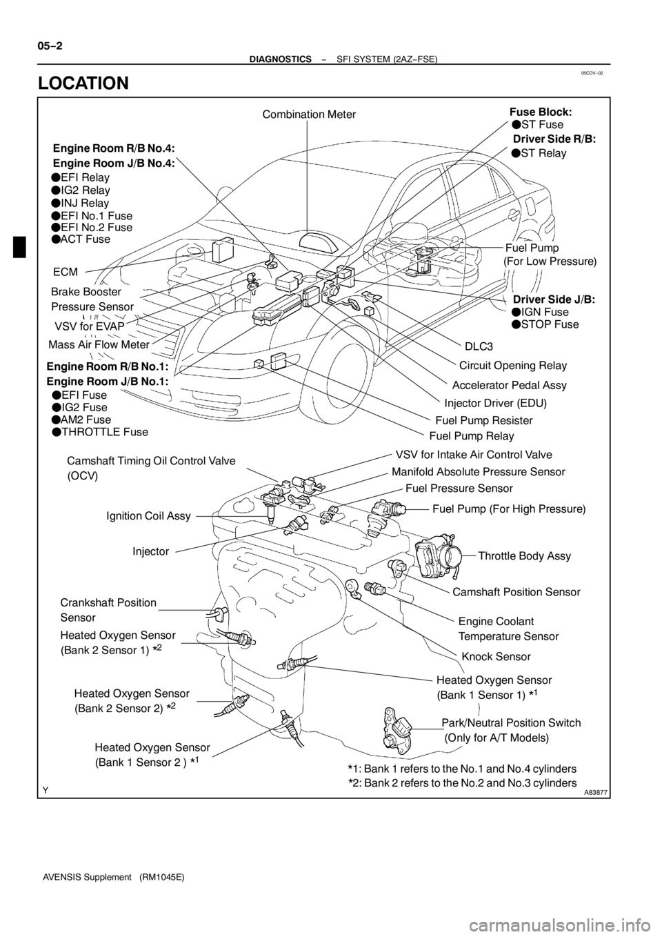
Ignition Coil Assy
Camshaft Position Sensor
VSV for EVAP
Combination Meter
DLC3
VSV for Intake Air Control Valve
Fuel Pump
ECM
Knock Sensor Camshaft Timing Oil Control Valve
(OCV)
Injector
Crankshaft Position
Sensor
Park/Neutral Position Switch
(Only for A/T Models)Engine Coolant
Temperature Sensor
Mass Air Flow Meter
Throttle Body Assy
Accelerator Pedal Assy
Heated Oxygen Sensor
(Bank 2 Sensor 2) *
2
Circuit Opening Relay
Heated Oxygen Sensor
(Bank1Sensor 2 ) *
1
Heated Oxygen Sensor
(Bank 2 Sensor1)*
2
Heated Oxygen Sensor
(Bank1Sensor1)*
1
Manifold Absolute Pressure Sensor
Fuel Pump (For High Pressure)
Injector Driver (EDU)
Brake Booster
Pressure Sensor
Fuel Pressure Sensor
(For Low Pressure)
FEFI Fuse
FIG2 Fuse
FAM2 Fuse
FTHROTTLE Fuse
FEFI Relay
FIG2 Relay
FINJ Relay
FEFI No.1Fuse
FEFI No.2 Fuse
FACT Fuse
FST Fuse
FIGN Fuse
FSTOP Fuse
FST Relay
Fuel Pump RelayFuel Pump Resister
*1: Bank1refers to the No.1and No.4 cylinders
*2: Bank 2 refers to the No.2 and No.3 cylinders
Engine Room R/B No.4:
Engine Room J/B No.4:Fuse Block:
Engine Room R/B No.1:
Engine Room J/B No.1:
Driver Side R/B:
Driver Side J/B: 05−2
− DIAGNOSTICSSFI SYSTEM (2AZ−FSE)
AVENSIS Supplement (RM1045E)
LOCATION
Page 4127 of 5135
054JE−09
A85347
Mass Air Flow Meter
DLC3
Accelerator Pedal Assy
(Accelerator Pedal
Position Sensor)
EDUECM
Engine Room R/B No. 1:
FEDU Relay
FEDU Fuse
Glow Plug Relay
Camshaft Position SensorInjector
Crankshaft Position Sensor
Engine Coolant Temperature Sensor Fuel Pressure Sensor
Fuse Block
FST Fuse
Driver Side J/B
FGAUGE Fuse
FSTOP Fuse
Driver Side R/B
FST Relay
E−VRV Pressure Discharge Valve Glow Plug
Exhaust Gas Temperature
Sensor (on down stream)Intake Air Temperature Sensor
EGR Valve
Turbo Pressure Sensor
Intake Shutter (Throttle Valve)
Suction Control Valve
Fuel Temperature Sensor
Supply Pump Exhaust Gas Temperature
Sensor (on up stream)
Exhaust Fuel Addition Injector
A/F Sensor
Engine Room R/B No. 3:
FGLOW Fuse
EGR Valve
Position Sensor
Intake Shutter
(Throttle Valve)
Position Sensor
Differential Pressure Sensor 05−254
− DIAGNOSTICSECD SYSTEM (1CD−FTV)(From September, 2003)
AVENSIS Supplement (RM1045E)
LOCATION
Page 4129 of 5135

A76882
Battery FL MAINIGN
B−G11
E9
2 6
Engine
Room
J/B No.4Engine Room
R/B No.1
AM2
1 2
B−G4
18Driver
Side J/B
B−W B−R
WECM
DH
DA B−R
B−R 1
1A 1
1
4A
1 4B(LHD) (RHD)IP1 IE41
1
I13
Ignition Switch
AM2
IG2
(LHD)J8C
(RHD)J26A
(LHD)J8C
(RHD)J26AB−WCheck
Engine
Warning
LightW
C11
Combination Meter
229
J/C Engine Room
J/B No.1
− DIAGNOSTICSSFI SYSTEM (2AZ−FSE)
05−251
AVENSIS Supplement (RM1045E)
CHECK ENGINE WARNING LIGHT CIRCUIT
CIRCUIT DESCRIPTION
The CHK ENG is used to indicate the ECM’s detection of a vehicle malfunction.
The instrument panel IGN fuse provides the circuit power and the ECM provides the circuit ground that illumi-
nates the CHK ENG.
CHK ENG operations should be checked visually:
The CHK ENG should be illuminated when the ignition is first turned to ON. If the CHK ENG is always ON
or OFF, use the hand−held tester and follow the procedures below to determine the cause of the problem.
WIRING DIAGRAM
INSPECTION PROCEDURE
HINT:
Troubleshoot each trouble symptom in accordance with the chart below.
CHK ENG remains onStart inspection from step1
CHK ENG is not illuminatedStart inspection from step 3
05CJB−02
Page 4138 of 5135

A79096
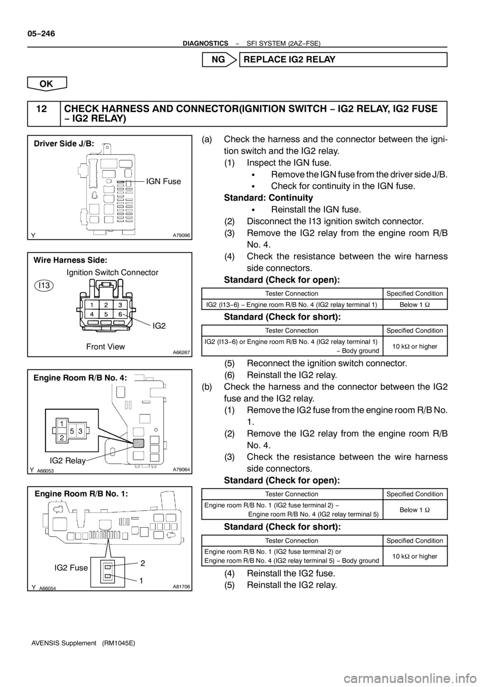
Driver Side J/B:
IGN Fuse
A66267
Ignition Switch Connector
Wire Harness Side:
IG2 I13
Front View
A66053A79064IG2 Relay
Engine Room R/B No. 4:
A66054A81706
IG2 Fuse
Engine Room R/B No.1:
2
1 05−246
− DIAGNOSTICSSFI SYSTEM (2AZ−FSE)
AVENSIS Supplement (RM1045E)
NG REPLACE IG2 RELAY
OK
12 CHECK HARNESS AND CONNECTOR(IGNITION SWITCH−IG2 RELAY, IG2 FUSE
−IG2 RELAY)
(a) Check the harness and the connector between the igni-
tion switch and the IG2 relay.
(1) Inspect the IGN fuse.
SRemove the IGN fuse from the driver side J/B.
SCheck for continuity in the IGN fuse.
Standard: Continuity
SReinstall the IGN fuse.
(2) Disconnect the I13 ignition switch connector.
(3) Remove the IG2 relay from the engine room R/B
No. 4.
(4) Check the resistance between the wire harness
side connectors.
Standard (Check for open):
Tester ConnectionSpecified Condition
IG2 (I13−6)−Engine room R/B No. 4 (IG2 relay terminal 1)Below 1�
Standard (Check for short):
Tester ConnectionSpecified Condition
IG2 (I13−6) or Engine room R/B No. 4 (IG2 relay terminal 1)
−Body ground10 k�or higher
(5) Reconnect the ignition switch connector.
(6) Reinstall the IG2 relay.
(b) Check the harness and the connector between the IG2
fuse and the IG2 relay.
(1) Remove the IG2 fuse from the engine room R/B No.
1.
(2) Remove the IG2 relay from the engine room R/B
No. 4.
(3) Check the resistance between the wire harness
side connectors.
Standard (Check for open):
Tester ConnectionSpecified Condition
Engine room R/B No. 1 (IG2 fuse terminal 2)−
Engine room R/B No. 4 (IG2 relay terminal 5)Below 1�
Standard (Check for short):
Tester ConnectionSpecified Condition
Engine room R/B No. 1 (IG2 fuse terminal 2) or
Engine room R/B No. 4 (IG2 relay terminal 5)−Body ground10 k�or higher
(4) Reinstall the IG2 fuse.
(5) Reinstall the IG2 relay.
Page 4143 of 5135

A79096
Driver Side J/B:
IGN Fuse
B68363
I13 LOCK
ACC
ON
START35_ 35_ 55_
A67446ECM Connecter
E11E9
E1 (−)MREL (+)
05−238
− DIAGNOSTICSSFI SYSTEM (2AZ−FSE)
AVENSIS Supplement (RM1045E)
4 CHECK FUSE(IGN FUSE)
(a) Remove the IGN fuse from the driver side J/B.
(b) Check for continuity in the IGN fuse.
Standard: Continuity
(c) Reinstall the IGN fuse.
NG CHECK FOR SHORT IN ALL HARNESSES AND
COMPONENTS CONNECTED TO FUSE
OK
5 INSPECT IGNITION OR STARTER SWITCH ASSY
(a) Disconnect the I13 ignition switch connector.
(b) Measure the resistance between the connector terminals
shown in the chart below.
Standard:
Switch PositionTester ConnectionSpecified Condition
LOCKAll Terminals10 k�or higher
ACC2−3Below 1�
ON1−3, 2−3, 4−6Below 1�
START1−3, 4−5, 4−6Below 1�
(c) Reconnect the ignition switch connector.
NG REPLACE IGNITION OR STARTER SWITCH
ASSY (GO TO NEXT STEP 6 AFTER THE RE-
PLACEMENT)
OK
CHECK AND REPAIR HARNESS AND CONNECTOR(BATTERY−IGNITION SWITCH, IGNITION
SWITCH−ECM)
6 INSPECT ECM(MREL VOLTAGE)
(a) Turn the ignition switch to ON.
(b) Measure the voltage between the terminals of the E9 and
E11 ECM connectors.
Standard:
Tester ConnectionSpecified Condition
MREL (E9−8)−E1 (E11−1)9to14V
NG REPLACE ECM (See page10−65 of Pub. No.
RM1018E AVENSIS)
OK
Page 4144 of 5135
A66054
Engine Room R/B No.1:
EFI Fuse
B16200
A66053A79065
Engine Room R/B No. 4:
EFI No.1 Fuse
− DIAGNOSTICSSFI SYSTEM (2AZ−FSE)
05−239
AVENSIS Supplement (RM1045E)
7 CHECK FUSE(EFI FUSE)
(a) Remove the EFI fuse from the engine room R/B No. 1.
(b) Check for continuity in the EFI fuse.
Standard: Continuity
(c) Reinstall the EFI fuse.
NG CHECK FOR SHORT IN ALL HARNESSES AND
COMPONENTS CONNECTED TO FUSE
OK
8 INSPECT EFI RELAY
(a) Remove the EFI relay from the engine room R/B No. 4.
(b) Check for continuity in the EFI relay.
Standard:
Tester ConnectionSpecified Condition
1−2Continuity
3−5No Continuity
3−5Continuity
(Apply battery voltage to terminals 1 and 2)
(c) Reinstall the EFI relay.
NG REPLACE EFI RELAY
OK
9 CHECK FUSE(EFI NO.1FUSE)
(a) Remove the EFI No. 1 fuse from the engine room R/B No.
4.
(b) Check for continuity in the EFI No. 1 fuse.
Standard: Continuity
(c) Reinstall the EFI No. 1 fuse.
NG CHECK FOR SHORT IN ALL HARNESSES AND
COMPONENTS CONNECTED TO FUSE
OK
Page 4145 of 5135

A66053
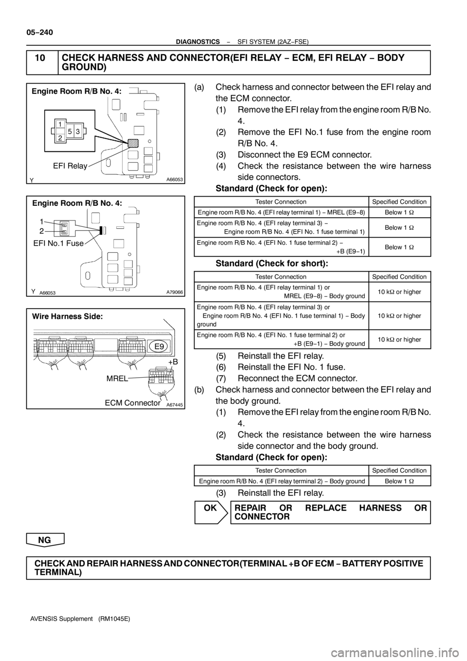
Engine Room R/B No. 4:
EFI Relay
A66053A79066
Engine Room R/B No. 4:
EFI No.1 Fuse
1
2
A67445
MREL
E9
ECM Connector+B
Wire Harness Side:
05−240
− DIAGNOSTICSSFI SYSTEM (2AZ−FSE)
AVENSIS Supplement (RM1045E)
10 CHECK HARNESS AND CONNECTOR(EFI RELAY−ECM, EFI RELAY−BODY
GROUND)
(a) Check harness and connector between the EFI relay and
the ECM connector.
(1) Remove the EFI relay from the engine room R/B No.
4.
(2) Remove the EFI No.1 fuse from the engine room
R/B No. 4.
(3) Disconnect the E9 ECM connector.
(4) Check the resistance between the wire harness
side connectors.
Standard (Check for open):
Tester ConnectionSpecified Condition
Engine room R/B No. 4 (EFI relay terminal 1)−MREL (E9−8)Below 1�
Engine room R/B No. 4 (EFI relay terminal 3)−
Engine room R/B No. 4 (EFI No. 1 fuse terminal 1)Below 1�
Engine room R/B No. 4 (EFI No. 1 fuse terminal 2)−
+B (E9−1)Below 1�
Standard (Check for short):
Tester ConnectionSpecified Condition
Engine room R/B No. 4 (EFI relay terminal 1) or
MREL (E9−8)−Body ground10 k�or higher
Engine room R/B No. 4 (EFI relay terminal 3) or
Engine room R/B No. 4 (EFI No. 1 fuse terminal 1)−Body
ground
10 k�or higher
Engine room R/B No. 4 (EFI No. 1 fuse terminal 2) or
+B (E9−1)−Body ground10 k�or higher
(5) Reinstall the EFI relay.
(6) Reinstall the EFI No. 1 fuse.
(7) Reconnect the ECM connector.
(b) Check harness and connector between the EFI relay and
the body ground.
(1) Remove the EFI relay from the engine room R/B No.
4.
(2) Check the resistance between the wire harness
side connector and the body ground.
Standard (Check for open):
Tester ConnectionSpecified Condition
Engine room R/B No. 4 (EFI relay terminal 2)−Body groundBelow 1�
(3) Reinstall the EFI relay.
OK REPAIR OR REPLACE HARNESS OR
CONNECTOR
NG
CHECK AND REPAIR HARNESS AND CONNECTOR(TERMINAL +B OF ECM−BATTERY POSITIVE
TERMINAL)
Page 4154 of 5135

A85832
From Battery+BM
+M
−M
ME01ECM
Motor Control
Circuit Throttle Control MotorTHROTTLE fuse
− DIAGNOSTICSSFI SYSTEM (2AZ−FSE)
05−219
AVENSIS Supplement (RM1045E)
DTC P2118 THROTTLE ACTUATOR CONTROL MOTOR
CURRENT RANGE/PERFORMANCE
CIRCUIT DESCRIPTION
The Electronic Throttle Control System (ETCS) has a dedicated power supply circuit. The voltage (+BM) is
monitored and when the voltage is low (less than 4V), the ECM concludes that the ETCS has a fault and
current to the throttle control motor is cut.
When the voltage becomes unstable, the ETCS itself becomes unstable. For this reason, when the voltage
is low, the current to the motor is cut. If repairs are made and the system has returned to normal, turn the
ignition switch to OFF. The ECM then allows current to flow to the motor and the motor can be restarted.
HINT:
This Electrical Throttle Control System (ETCS) does not use a throttle cable.
DTC No.DTC Detection ConditionTrouble Area
P2118Open in ETCS power source circuit (+BM)
(1trip detection logic)SOpen in ETCS power source circuit
STHROTTLE fuse
SECM
05HIQ−01