Page 3881 of 5135
A76968
C2
(±) (+)
Camshaft Timing Oil Control Valve
05±178
± DIAGNOSTICSSFI SYSTEM (1AZ±FE)
AVENSIS REPAIR MANUAL (RM1018E)
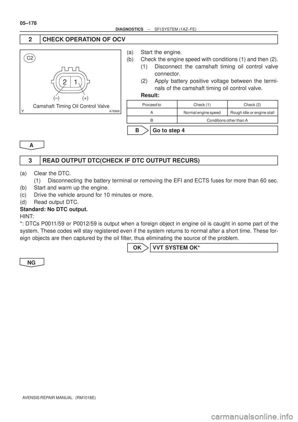
2 CHECK OPERATION OF OCV
(a) Start the engine.
(b) Check the engine speed with conditions (1) and then (2).
(1) Disconnect the camshaft timing oil control valve
connector.
(2) Apply battery positive voltage between the termi-
nals of the camshaft timing oil control valve.
Result:
Proceed toCheck (1)Check (2)
ANormal engine speedRough idle or engine stall
BConditions other than A
B Go to step 4
A
3 READ OUTPUT DTC(CHECK IF DTC OUTPUT RECURS)
(a) Clear the DTC.
(1) Disconnecting the battery terminal or removing the EFI and ECTS fuses for more than 60 sec.
(b) Start and warm up the engine.
(c) Drive the vehicle around for 10 minutes or more.
(d) Read output DTC.
Standard: No DTC output.
HINT:
*: DTCs P0011/59 or P0012/59 is output when a foreign object in engine oil is caught in some part of the
system. These codes will stay registered even if the system returns to normal after a short time. These for-
eign objects are then captured by the oil filter, thus eliminating the source of the problem.
OK VVT SYSTEM OK*
NG
Page 3883 of 5135
05±180
±
DIAGNOSTICS SFI SYSTEM(1AZ±FE)
AVENSIS REPAIR MANUAL (RM1018E)
9REPLACE CAMSHAFT TIMING GEAR ASSY
GO
10CHECK FOR BLOCKAGE(OCV, OIL CHECK VALVE AND OIL HOLE)
NGREPAIR OR REPLACE
OK
11READ OUTPUT DTC(CHECK IF DTC OUTPUT RECURS)
(a)Clear the DTC. (1)Disconnecting the battery terminal or removing the EFI and ECTS fuses for more than 6\
0 sec.
(b)Start and warm up the engine.
(c)Drive the vehicle around for 10 minutes or more.
(d)Read output DTC.
Standard: No DTC output.
HINT:
*: DTCs P0011/59 or P0012/59 is output when a foreign object in engine oil is caught in some part of \
the
system. These codes will stay registered even if the system returns to normal a\
fter a short time. These for-
eign objects are then captured by the oil filter, thus eliminating the source of the problem.
OKVVT SYSTEM OK*
NG
CHECK AND REPLACE ECM (See page 01±32)
Page 3888 of 5135
3
2
145678
910111213141516
DLC3
A04550
TC
CG
ONON
ONON
OFFOFFOFF
0.25sec.
0.25sec.
FI0294
BR3589
Start
0.5 sec.1.5 sec.4.5 sec.
ON
OFF
One Cycle 0.5 sec.
2.5
sec.
Repeat
4.5 sec.
±
DIAGNOSTICS SFI SYSTEM(1AZ±FE)
05±153
AVENSIS REPAIR MANUAL (RM1018E)
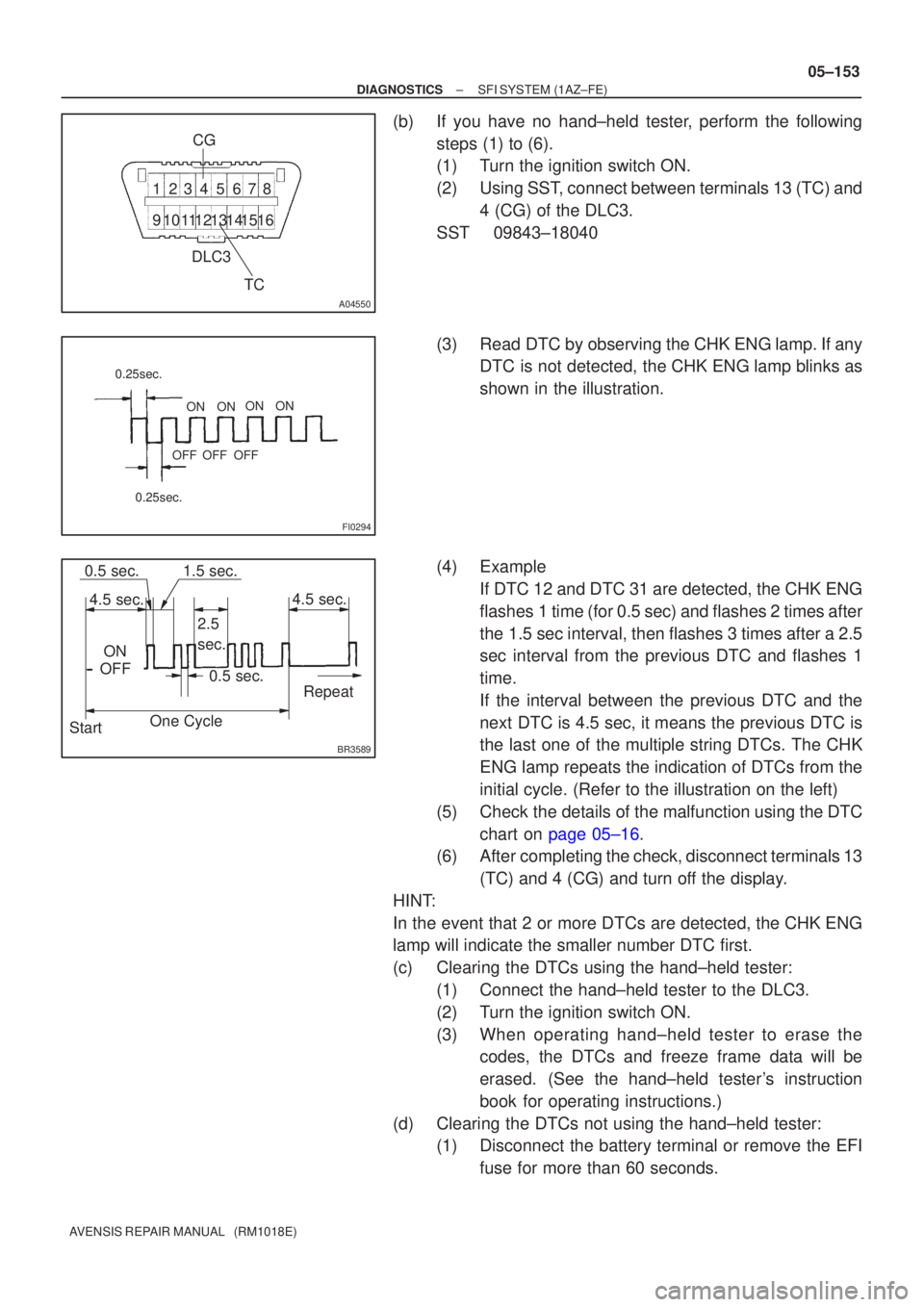
(b)If you have no hand±held tester, perform the following
steps (1) to (6).
(1)Turn the ignition switch ON.
(2)Using SST, connect between terminals 13 (TC) and4 (CG) of the DLC3.
SST09843±18040
(3)Read DTC by observing the CHK ENG lamp. If any DTC is not detected, the CHK ENG lamp blinks as
shown in the illustration.
(4)Example If DTC 12 and DTC 31 are detected, the CHK ENG
flashes 1 time (for 0.5 sec) and flashes 2 times after
the 1.5 sec interval, then flashes 3 times after a 2.5
sec interval from the previous DTC and flashes 1
time.
If the interval between the previous DTC and the
next DTC is 4.5 sec, it means the previous DTC is
the last one of the multiple string DTCs. The CHK
ENG lamp repeats the indication of DTCs from the
initial cycle. (Refer to the illustration on the left)
(5)Check the details of the malfunction using the DTC chart on page 05±16.
(6) After completing the check, disconnect terminals 13
(TC) and 4 (CG) and turn off the display.
HINT:
In the event that 2 or more DTCs are detected, the CHK ENG
lamp will indicate the smaller number DTC first.
(c) Clearing the DTCs using the hand±held tester: (1) Connect the hand±held tester to the DLC3.
(2) Turn the ignition switch ON.
(3) When operating hand±held tester to erase thecodes, the DTCs and freeze frame data will be
erased. (See the hand±held tester's instruction
book for operating instructions.)
(d) Clearing the DTCs not using the hand±held tester: (1) Disconnect the battery terminal or remove the EFI
fuse for more than 60 seconds.
Page 3890 of 5135
±
DIAGNOSTICS SFI SYSTEM(1AZ±FE)
05±155
AVENSIS REPAIR MANUAL (RM1018E)
(b)Clearing the DTCs using the hand±held tester
(1)Connect the hand±held tester to DLC3.
(2)Turn the ignition switch ON.
(3)When operating hand±held tester to erase thecodes, the DTCs and freeze frame data will be
erased. (See the hand±held tester's instruction
book for operating instructions.)
(c)Clearing the DTCs not using the hand±held tester: (1)Disconnecting the battery terminal or remove theEFI fuse for more than 60 seconds.
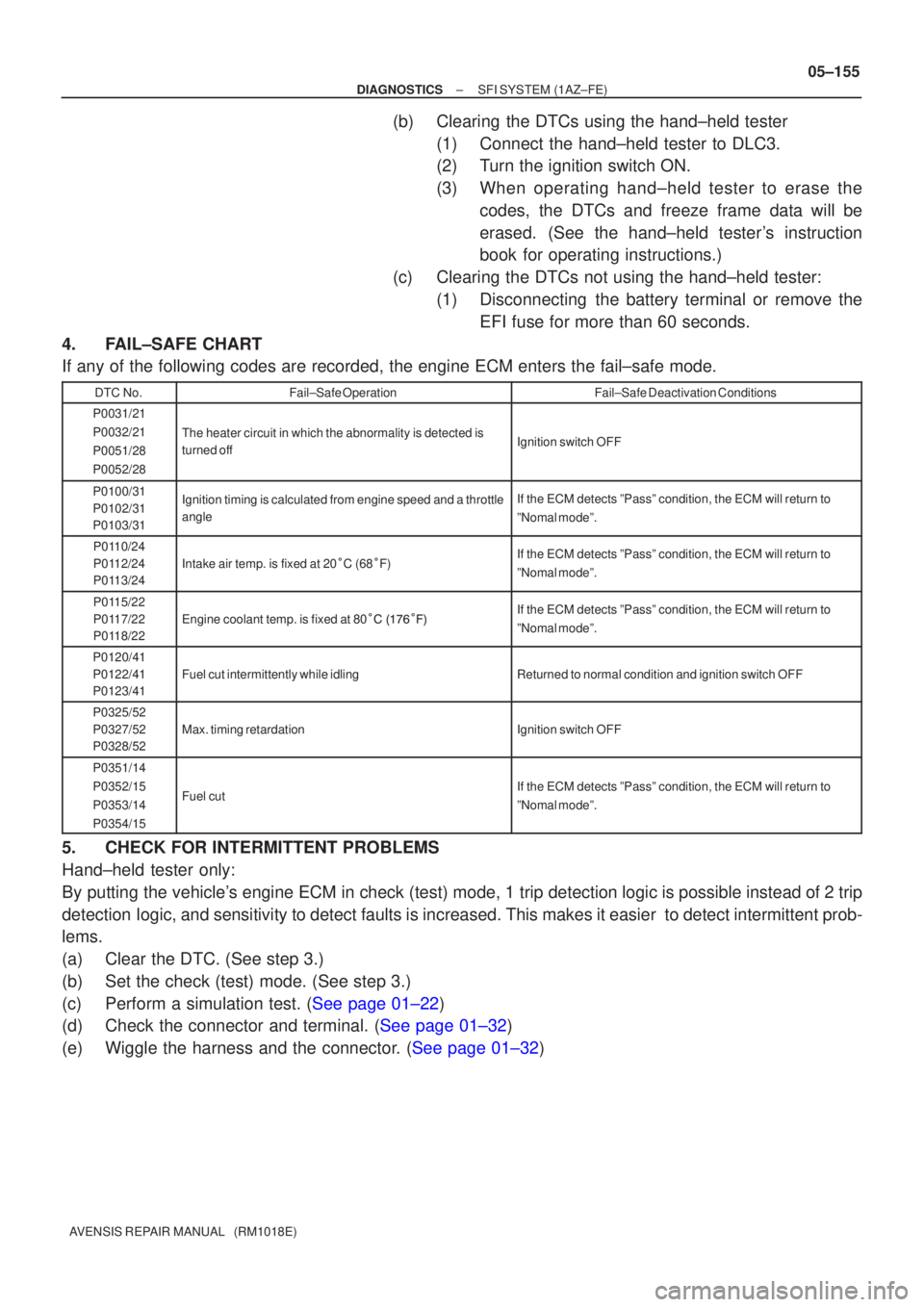
4.FAIL±SAFE CHART
If any of the following codes are recorded, the engine ECM enters the fa\
il±safe mode.
DTC No.Fail±Safe OperationFail±Safe Deactivation Conditions
P0031/21
P0032/21
P0051/28
P0052/28
The heater circuit in which the abnormality is detected is
turned offIgnition switch OFF
P0100/31
P0102/31
P0103/31Ignition timing is calculated from engine speed and a throttle
angleIf the ECM detects ºPassº condition, the ECM will return to
ºNomal modeº.
P0110/24
P0112/24
P0113/24
Intake air temp. is fixed at 20 C (68 F)If the ECM detects ºPassº condition, the ECM will return to
ºNomal modeº.
P0115/22
P0117/22
P0118/22
Engine coolant temp. is fixed at 80 ����� \b�If the ECM detects ºPassº condition, the ECM will return to
ºNomal modeº.
P0120/41
P0122/41
P0123/41
Fuel cut intermittently while idlingReturned to normal condition and ignition switch OFF
P0325/52
P0327/52
P0328/52
Max. timing retardationIgnition switch OFF
P0351/14
P0352/15
P0353/14
P0354/15
Fuel cutIf the ECM detects ºPassº condition, the ECM will return to
ºNomal modeº.
5.CHECK FOR INTERMITTENT PROBLEMS
Hand±held tester only:
By putting the vehicle's engine ECM in check (test) mode, 1 trip detection logic is possible instead of 2 trip
detection logic, and sensitivity to detect faults is increased. This makes it eas\
ier to detect intermittent prob-
lems.
(a)Clear the DTC. (See step 3.)
(b)Set the check (test) mode. (See step 3.)
(c)Perform a simulation test. (See page 01±22)
(d)Check the connector and terminal. (See page 01±32)
(e)Wiggle the harness and the connector. (See page 01±32)
Page 3906 of 5135
A76821
Wire Harness Side
B1S1B2S1 H7 H9
Heated Oxygen Sensor Connector OX
HT
OX
HT
E1E1
A76823
OX2A
ECM Connector E12
OX1A
HT2A HT1A
E2 E13
A72920
Reference (Bank 1 Sensor 1 System Drawing)
Heated Oxygen Sensor
EFI Relay
Heater
Sensor
OX1A HT1A
Duty
Control ECM
From
Battery
EFI Fuse
E2 EFI No. 2
Fuse
MREL OX HT
E1 +B
± DIAGNOSTICSSFI SYSTEM (1AZ±FSE)
05±385
AVENSIS REPAIR MANUAL (RM1018E)
NG REPLACE EFI RELAY
OK
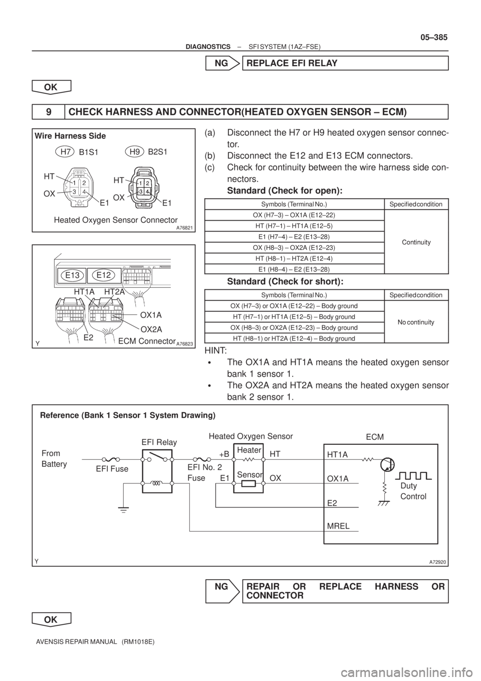
9 CHECK HARNESS AND CONNECTOR(HEATED OXYGEN SENSOR ± ECM)
(a) Disconnect the H7 or H9 heated oxygen sensor connec-
tor.
(b) Disconnect the E12 and E13 ECM connectors.
(c) Check for continuity between the wire harness side con-
nectors.
Standard (Check for open):
Symbols (Terminal No.)Specified condition
OX (H7±3) ± OX1A (E12±22)
HT (H7±1) ± HT1A (E12±5)
E1 (H7±4) ± E2 (E13±28)ContinuityOX (H8±3) ± OX2A (E12±23)Continuity
HT (H8±1) ± HT2A (E12±4)
E1 (H8±4) ± E2 (E13±28)
Standard (Check for short):
Symbols (Terminal No.)Specified condition
OX (H7±3) or OX1A (E12±22) ± Body ground
HT (H7±1) or HT1A (E12±5) ± Body groundNo continuityOX (H8±3) or OX2A (E12±23) ± Body groundNo continuity
HT (H8±1) or HT2A (E12±4) ± Body ground
HINT:
�The OX1A and HT1A means the heated oxygen sensor
bank 1 sensor 1.
�The OX2A and HT2A means the heated oxygen sensor
bank 2 sensor 1.
NG REPAIR OR REPLACE HARNESS OR
CONNECTOR
OK
Page 3914 of 5135
A72920
Reference (Bank 1 Sensor 2 System Drawing)
Heated Oxygen Sensor
EFI Relay
Heater
Sensor
OX1B HT1B
Duty
Control ECM
From
Battery
EFI Fuse
O1B± EFI No. 2
Fuse
MREL OX HT
E1 +B
± DIAGNOSTICSSFI SYSTEM (1AZ±FSE)
05±393
AVENSIS REPAIR MANUAL (RM1018E)
NG REPAIR OR REPLACE HARNESS OR
CONNECTOR
OK
REPLACE HEATED OXYGEN SENSOR
6 PERFORM CONFIRMATION DRIVING PATTERN
HINT:
Clear all DTCs prior to performing the confirmation driving pattern.
GO
7 READ OUTPUT DTC(DTC P0136 AND/OR P0156 ARE OUTPUT AGAIN)
(a) Read the DTC using the hand±held tester.
Result:
Display (DTC output)Proceed to
ºP0136 and/or P0156º are not output againA
ºP0136 and/or P0156º are output againB
B REPLACE HEATED OXYGEN SENSOR
A
CHECK FOR INTERMITTENT PROBLEMS
Page 3919 of 5135
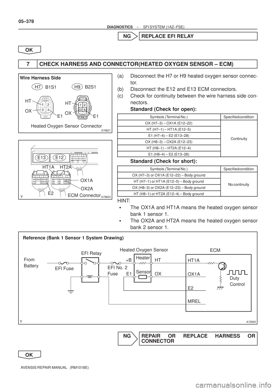
A76821
Wire Harness Side
B1S1B2S1 H7 H9
Heated Oxygen Sensor Connector OX
HT
OX
HT
E1E1
A76823
OX2A
ECM Connector E12
OX1A
HT2A HT1A
E2 E13
A72920
Reference (Bank 1 Sensor 1 System Drawing)
Heated Oxygen Sensor
EFI Relay
Heater
Sensor
OX1A HT1A
Duty
Control ECM
From
Battery
EFI Fuse
E2 EFI No. 2
Fuse
MREL OX HT
E1 +B
05±378
± DIAGNOSTICSSFI SYSTEM (1AZ±FSE)
AVENSIS REPAIR MANUAL (RM1018E)
NG REPLACE EFI RELAY
OK
7 CHECK HARNESS AND CONNECTOR(HEATED OXYGEN SENSOR ± ECM)
(a) Disconnect the H7 or H9 heated oxygen sensor connec-
tor.
(b) Disconnect the E12 and E13 ECM connectors.
(c) Check for continuity between the wire harness side con-
nectors.
Standard (Check for open):
Symbols (Terminal No.)Specified condition
OX (H7±3) ± OX1A (E12±22)
HT (H7±1) ± HT1A (E12±5)
E1 (H7±4) ± E2 (E13±28)ContinuityOX (H8±3) ± OX2A (E12±23)Continuity
HT (H8±1) ± HT2A (E12±4)
E1 (H8±4) ± E2 (E13±28)
Standard (Check for short):
Symbols (Terminal No.)Specified condition
OX (H7±3) or OX1A (E12±22) ± Body ground
HT (H7±1) or HT1A (E12±5) ± Body groundNo continuityOX (H8±3) or OX2A (E12±23) ± Body groundNo continuity
HT (H8±1) or HT2A (E12±4) ± Body ground
HINT:
�The OX1A and HT1A means the heated oxygen sensor
bank 1 sensor 1.
�The OX2A and HT2A means the heated oxygen sensor
bank 2 sensor 1.
NG REPAIR OR REPLACE HARNESS OR
CONNECTOR
OK
Page 3956 of 5135
A81016
ECM
STA
E97
B±Y
IJW±BJ12
B B
J13
J/C W±B 1 5
32 1AM2 2
B
B±R1
S51
S4
Starter
Battery7IK1
FL MAIN 3 3
Engine Room
R/B No. 3
B B 55
55 1
11A
BB±R
IE41
(LHD)IP11
(RHD)B±R
Engine
Room
R/B No. 1
Driver
Side R/B ST
Relay
2
DJ
9
DADriver
Side J/B B±R
B±RI13
Ignition Switch
4
5
AM2 ST2B±Y
B±Y
6
2ST 1
6 Fuse
Block
B±WB±Y B±YB±Y
J12
A C
J13C
J13
± DIAGNOSTICSECD SYSTEM (1CD±FTV)
05±691
AVENSIS REPAIR MANUAL (RM1018E)
STARTER SIGNAL CIRCUIT
CIRCUIT DESCRIPTION
HINT:
While the engine is being cranked, current flows from terminal ST2 of the ignition switch to the ST relay coil
and also current flows to terminal STA of the ECM (STA signal).
WIRING DIAGRAM
05B5Y±02