Page 3081 of 5135
610CK±02
61±2
±
SEAT BELT SEAT BELT WARNING SYSTEM
AVENSIS REPAIR MANUAL (RM1018E)
PROBLEM SYMPTOMS TABLE
SymptomSuspected AreaSee Page
Driver side seat belt warning lamp does not light up
1. Fuse
2. Combination meter
3. Airbag sensor assy center
4. Front seat inner belt assy LH
5. Wire harness�
71±21
60±62 61±3 �
Passenger side seat belt warning lamp does not light up
1. Fuse
2. Passenger side seat belt warning lamp assy
3. Front seat inner belt assy RH
4. Wire harness�
61±3
61±3 �
Page 3093 of 5135

PROBLEM SYMPTOMS TABLE
1.FRONT WIPER AND WASHER SYSTEM (W/O AUTO WIPER SYSTEM)
SymptomSuspect AreaSee page
F")
660CK±01
66±2
±
WIPER & WASHER WIPER AND WASHER SYSTEM
AVENSIS REPAIR MANUAL (RM1018E)
PROBLEM SYMPTOMS TABLE
1.FRONT WIPER AND WASHER SYSTEM (W/O AUTO WIPER SYSTEM)
SymptomSuspect AreaSee page
Front wipers and washers do not operate.
1. IG relay
2. WIP fuse
3. Windshield wiper switch assy
4. Wire harness or connector±
±
66±6 ±
Front wipers do not operate in LO or HI.
1. Windshield wiper switch assy
2. Windshield wiper motor assy
3. Wire harness or connector66±6
66±6±
Front wipers do not operate in INT.
1. Windshield wiper switch assy
2. Windshield wiper motor assy
3. Wire harness or connector66±6
66±6±
Front washer motor does not operate.
1 Windshield washer switch assy
2. Windshield washer motor assy
3. Wire harness or connector66±6
66±6±
Front wipers does not operate when washer switch in ON.
1. Windshield wiper switch assy
2. Windshield wiper motor assy
3. Wire harness or connector66±6
66±6±
Washer fluid does not operate.Washer hose and nozzle±
� When front wiper switch is in HI position, the wiper blade is in
contact with the body.
� When the front wiper switch is OFF, the wiper blade does not
retract or the retract position is wrong.
1. Windshield wiper motor assy
2. Front wiper arm installation position66±6
66±13
2. FRONT WIPER AND WASHER SYSTEM (W/ AUTO WIPER SYSTEM)
SymptomSuspect AreaSee page
Front wipers and washer do not operate.
1. IG1 relay
2. WIP fuse
3. Windshield wiper switch assy
4. Windshield wiper relay assy
5. Wire harness or connector±
±
66±6
66±6 ±
Front wipers does not operate in LO
(Auto wiper system is normal).Windshield wiper switch assy66±6
Front wipers does not operate in HI
(Auto wiper system is normal).1. Windshield wiper switch assy
2. Wire harness or connector66±6
±
Front washer motor does not operate.
1. Windshield wiper switch assy
2. Windshield washer motor assy
3. Wire harness or connector66±6
66±6±
Auto wiper system does not operate.
1. Windshield wiper switch assy
2. Windshield wiper relay assy
3. Rain sensor
4. Wire harness or connector66±6
66±6
66±4±
Page 3094 of 5135

3. REAR WIPER AND WASHER SYSTEM
SymptomSuspect AreaSee page
Rear wiper and washers do not operate.
1. AMI fuse
2. RR W")
±
WIPER & WASHER WIPER AND WASHER SYSTEM
66±3
AVENSIS REPAIR MANUAL (RM1018E)
3. REAR WIPER AND WASHER SYSTEM
SymptomSuspect AreaSee page
Rear wiper and washers do not operate.
1. AMI fuse
2. RR WIP fuse
3. Windshield wiper switch assy
4. Wire harness or connector±
±
66±6 ±
Rear wiper does not operate in INT.
1. Windshield wiper switch assy
2. Rear wiper motor assy
3. Wire harness or connector66±6
66±6±
Rear washer motor does not operate.
1. Windshield washer switch assy
2. Rear washer motor assy
3. Wire harness or connector66±6
66±6±
Rear wiper does not operate when washer switch is in ON.
1. Windshield wiper switch assy
2. Rear wiper motor assy
3. Wire harness or connector66±6
66±6±
Rear washer fluid does not operate.Washer hose and nozzle±
�When rear wiper switch is in ON position, the wiper blade is in
contact with the body.
� When the wiper switch is OFF, the wiper blade does not retract
or the retract position is wrong.
1. Rear wiper motor assy
2. Rear wiper blade installation position66±6
66±17
4. HEADLAMP CLEANER SYSTEM
SymptomSuspect AreaSee page
Headlamp cleaner system does not operate.
1. H/CLN fuse
2. Headlamp cleaner switch assy
3. Windshield wiper switch assy (w/ HID)
4. Headlamp cleaner control relay
5. Intergeneration Relay
6. Wire harness or connector±
66±6
66±6
66±6 ±
±
Page 3096 of 5135
650T5±01
I35250
65±30
±
LIGHTING HEADLAMP LEVELING ECU ASSY
AVENSIS REPAIR MANUAL (RM1018E)
HEADLAMP LEVELING ECU ASSY
REPLACEMENT
1. REMOVE GLOVE COMPARTMENT DOOR ASSY (LHD STEERING POSITION TYPE) (See page 71±11)
2.REMOVE FUSE BOX OPENING COVER (RHD STEERING POSITION TYPE) (See page 71±11)
3. REMOVE LIGHT CONTROL ECU
(a) Disconnect the connector.
(b) Remove the bolt and headlamp leveling ECU assy.
4. INSTALL LIGHT CONTROL ECU
(a) Install the headlamp leveling ECU assy with the bolt.
(b) Connect the connector.
Page 3151 of 5135
69065±02
69±2
±
COMMUNICATION SYSTEM HORN SYSTEM
AVENSIS REPAIR MANUAL (RM1018E)
PROBLEM SYMPTOMS TABLE
SymptomSuspected AreaSee Page
Horn does not sound
1. Horn button switch
2. High pitched horn
3. Low pitched horn
4. HORN fuse
5. HORN relay
6. Wire harness±
69±3
69±3
69±3 ±
Page 3152 of 5135
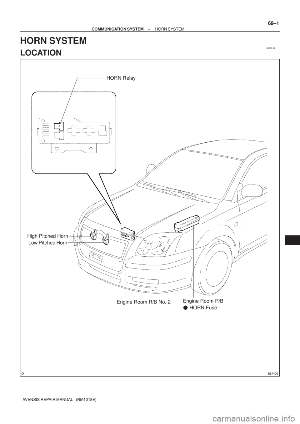
69064±02
B67409
Low Pitched HornHORN Relay
High Pitched Horn
Engine Room R/B No. 2Engine Room R/B
� HORN Fuse
± COMMUNICATION SYSTEMHORN SYSTEM
69±1
AVENSIS REPAIR MANUAL (RM1018E)
HORN SYSTEM
LOCATION
Page 3154 of 5135
I35270
Windshield Wiper Relay
Driver Side Relay Block Assy
Turn Signal Flasher Assy
Rear Fog Lamp Relay
Defogger Relay
Circuit Opening
Relay Assy
Instrument Panel
Junction Block Assy
Fuse Block Assy
LHD:
RHD:
Defogger Relay
Rear Fog Lamp RelayPassenger Side Relay Block Assy
Turn Signal Flasher Assy
Windshield Wiper Relay
Fuse Block Assy
Circuit Opening Relay Assy
Instrument Panel Junction Block Assy
68±2
± WIRINGPOWER SOURCE
AVENSIS REPAIR MANUAL (RM1018E)
Page 3155 of 5135
I35135
Engine Room Relay Block
FUSE RELAY
1. EMPS 50A
2. ±
3. A/F 20A
4. THROTTLE 10A
5. HORN 15A6. HAZARD 10A
7. ALT±S 7.5A
8. IG2 15A
9. EFI 20A
10. DCC 30A11. AM2 30A
12. MAIN 40A
13. ±
14. ±
15. ± A. FAN No.2
B. FAN No.1
C. FAN No.3
D. ±
E. ±
F. EMPS12B
CD E
F
11 1016 15
9 814
19 18 13
7 6
1217
34 5
Engine Room Relay Block ENGINE:
3ZZ±FE:
1ZZ±FE:
2AZ±FSE:
1AZ±FSE:
1AZ±FE:
A
16. RR DEF 30A
17. HTR 40A
18. RDI 30A
19. CDS 30A
ENGINE:
1CD±FTV:
1211
10 9 8 7 612
345 B
A
13
15 14
1619 18 17 20
CD
FUSE RELAY
1. MAIN 40A
2. RR DEF 30A
3. PWR HTR 25A
4. EFI 20A
5. HORN 15A6. F±HTR 25A
7. HAZARD 10A
8. AM2 30A
9. DCC 30A
10. ALT±S 7.5A11. ±
12. ±
13. ±
14. *1
15. *2 A. FAN No.1
B. FAN No.3
C. EDU
D. EFI MAIN16. RDI 40A
17. CDS 30A
18. HTR 40A
19. H/CLN 30A
20. AM1 No.1 50A
*1 VSC 25A (w/ VSC)
ABS 25A (w/o VSC)
*2 VSC 50A (w/ VSC)
ABS 40A (w/o VSC)
± WIRINGPOWER SOURCE
68±3
AVENSIS REPAIR MANUAL (RM1018E)

PROBLEM SYMPTOMS TABLE
SymptomSuspected AreaSee Page
Driver side seat belt warning lamp does not light up
1. Fus")

HEADLAMP LEVELING ECU ASSY
REPLACEMENT
1. REMOVE GLOVE COMPARTMENT DOOR ASSY (LHD STEERING POSITION TYP")

PROBLEM SYMPTOMS TABLE
SymptomSuspected AreaSee Page
Horn does not sound
1. Horn button switch
2. High pitched hor")