650SV±01
I33423
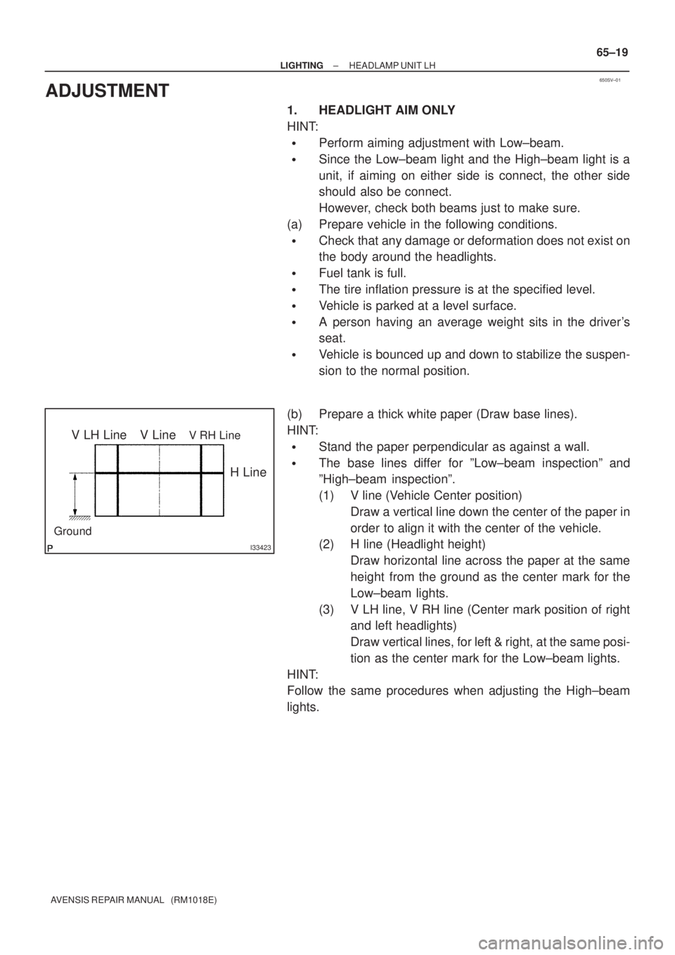
V LH LineV RH LineV Line
Ground
H Line
± LIGHTINGHEADLAMP UNIT LH
65±19
AVENSIS REPAIR MANUAL (RM1018E)
ADJUSTMENT
1. HEADLIGHT AIM ONLY
HINT:
�Perform aiming adjustment with Low±beam.
�Since the Low±beam light and the High±beam light is a
unit, if aiming on either side is connect, the other side
should also be connect.
However, check both beams just to make sure.
(a) Prepare vehicle in the following conditions.
�Check that any damage or deformation does not exist on
the body around the headlights.
�Fuel tank is full.
�The tire inflation pressure is at the specified level.
�Vehicle is parked at a level surface.
�A person having an average weight sits in the driver's
seat.
�Vehicle is bounced up and down to stabilize the suspen-
sion to the normal position.
(b) Prepare a thick white paper (Draw base lines).
HINT:
�Stand the paper perpendicular as against a wall.
�The base lines differ for ºLow±beam inspectionº and
ºHigh±beam inspectionº.
(1) V line (Vehicle Center position)
Draw a vertical line down the center of the paper in
order to align it with the center of the vehicle.
(2) H line (Headlight height)
Draw horizontal line across the paper at the same
height from the ground as the center mark for the
Low±beam lights.
(3) V LH line, V RH line (Center mark position of right
and left headlights)
Draw vertical lines, for left & right, at the same posi-
tion as the center mark for the Low±beam lights.
HINT:
Follow the same procedures when adjusting the High±beam
lights.
I35248
V LH Line
V RH Line
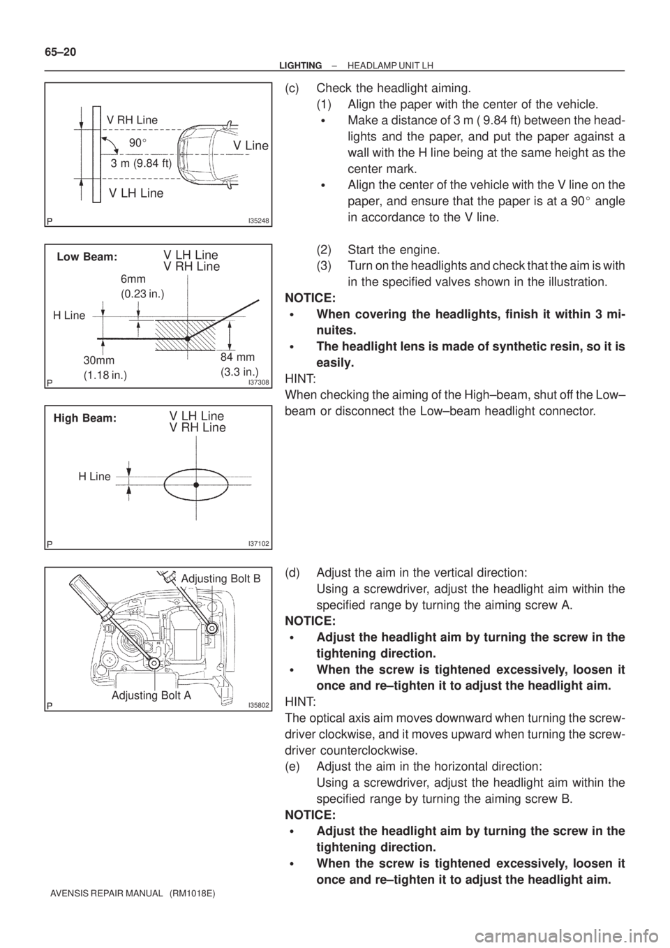
V Line90�
3 m (9.84 ft)
I37308
Low Beam:V LH Line
V RH Line
30mm
(1.18 in.)84 mm
(3.3 in.)
H Line6mm
(0.23 in.)
I37102
High Beam:V LH Line
V RH Line
H Line
I35802Adjusting Bolt A
Adjusting Bolt B
65±20
± LIGHTINGHEADLAMP UNIT LH
AVENSIS REPAIR MANUAL (RM1018E)
(c) Check the headlight aiming.
(1) Align the paper with the center of the vehicle.
�Make a distance of 3 m ( 9.84 ft) between the head-
lights and the paper, and put the paper against a
wall with the H line being at the same height as the
center mark.
�Align the center of the vehicle with the V line on the
paper, and ensure that the paper is at a 90� angle
in accordance to the V line.
(2) Start the engine.
(3) Turn on the headlights and check that the aim is with
in the specified valves shown in the illustration.
NOTICE:
�When covering the headlights, finish it within 3 mi-
nuites.
�The headlight lens is made of synthetic resin, so it is
easily.
HINT:
When checking the aiming of the High±beam, shut off the Low±
beam or disconnect the Low±beam headlight connector.
(d) Adjust the aim in the vertical direction:
Using a screwdriver, adjust the headlight aim within the
specified range by turning the aiming screw A.
NOTICE:
�Adjust the headlight aim by turning the screw in the
tightening direction.
�When the screw is tightened excessively, loosen it
once and re±tighten it to adjust the headlight aim.
HINT:
The optical axis aim moves downward when turning the screw-
driver clockwise, and it moves upward when turning the screw-
driver counterclockwise.
(e) Adjust the aim in the horizontal direction:
Using a screwdriver, adjust the headlight aim within the
specified range by turning the aiming screw B.
NOTICE:
�Adjust the headlight aim by turning the screw in the
tightening direction.
�When the screw is tightened excessively, loosen it
once and re±tighten it to adjust the headlight aim.