2005 NISSAN NAVARA change time
[x] Cancel search: change timePage 976 of 3171
DI-66
COMPASS
COMPASS
PFP:24835
System DescriptionEKS00M4Z
This unit displays earth magnetism and heading direction of vehicle.
DIRECTION DISPLAY
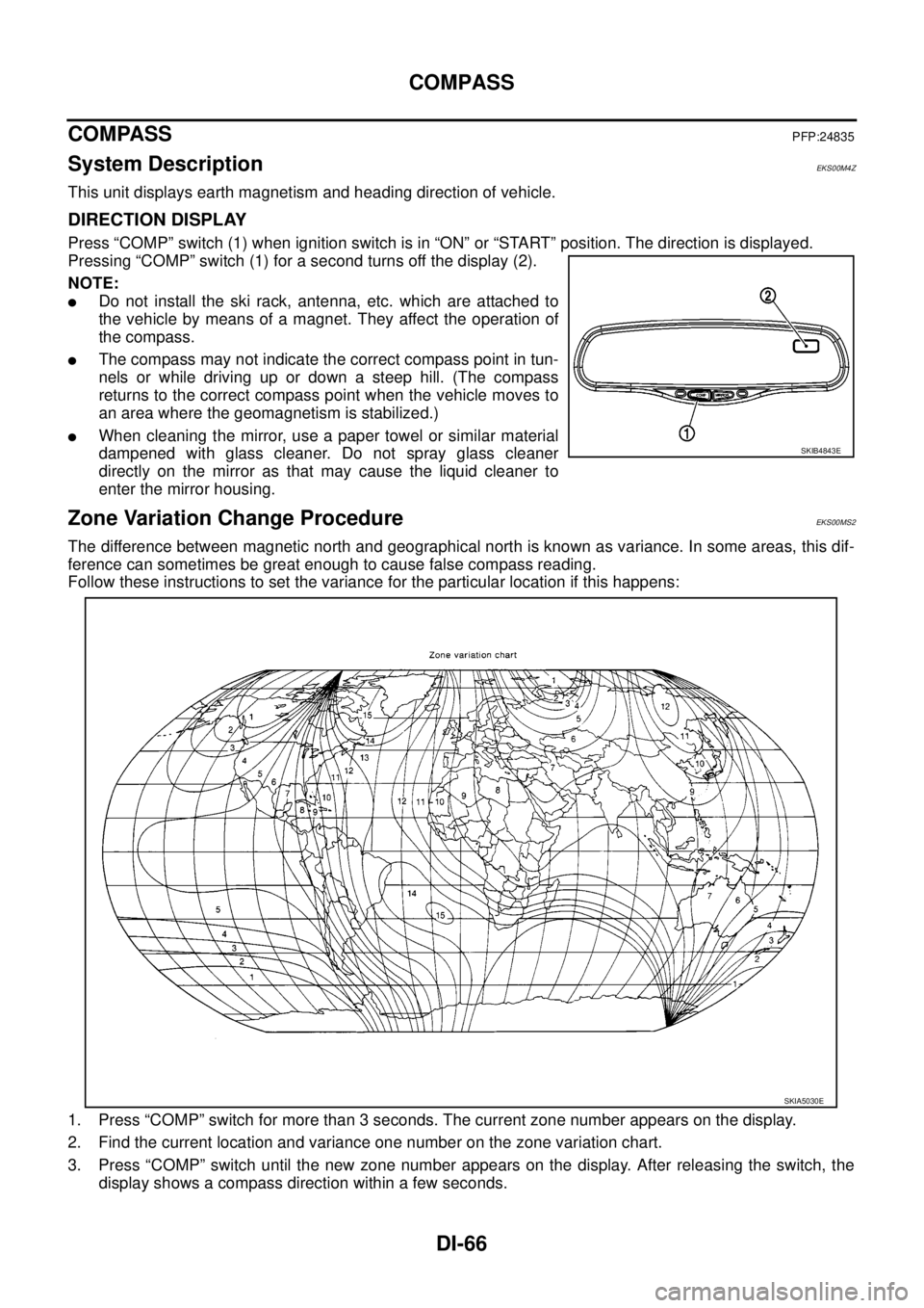
Press “COMP” switch (1) when ignition switch is in “ON” or “START” position. The direction is displayed.
Pressing “COMP” switch (1) for a second turns off the display (2).
NOTE:
lDo not install the ski rack, antenna, etc. which are attached to
the vehicle by means of a magnet. They affect the operation of
the compass.
lThe compass may not indicate the correct compass point in tun-
nels or while driving up or down a steep hill. (The compass
returns to the correct compass point when the vehicle moves to
an area where the geomagnetism is stabilized.)
lWhen cleaning the mirror, use a paper towel or similar material
dampened with glass cleaner. Do not spray glass cleaner
directly on the mirror as that may cause the liquid cleaner to
enter the mirror housing.
Zone Variation Change ProcedureEKS00MS2
The difference between magnetic north and geographical north is known as variance. In some areas, this dif-
ference can sometimes be great enough to cause false compass reading.
Follow these instructions to set the variance for the particular location if this happens:
1. Press “COMP” switch for more than 3 seconds. The current zone number appears on the display.
2. Find the current location and variance one number on the zone variation chart.
3. Press “COMP” switch until the new zone number appears on the display. After releasing the switch, the
display shows a compass direction within a few seconds.
SKIB4843E
SKIA5030E
Page 1007 of 3171
ON BOARD DIAGNOSTIC (OBD) SYSTEM
EC-27
C
D
E
F
G
H
I
J
K
L
MA
EC
ON BOARD DIAGNOSTIC (OBD) SYSTEMPFP:00028
DTC Detection LogicEBS01KCN
When a malfunction is detected, the malfunction (DTC) and freeze frame data are stored in the ECM memory.
The MI will light up each time the ECM detects malfunction. For diagnostic items causing the MI to light up,
refer toEC-6, "
INDEX FOR DTC".
Diagnostic Trouble Code (DTC)EBS01KCO
HOW TO READ DTC
The DTC can be read by the following methods.
With CONSULT-II
CONSULT-IIdisplaystheDTCin"SELF-DIAGRESULTS"mode.Example:P0117,P0335,P1268,etc.These
DTCs are prescribed by ISO15031-5.
(CONSULT-II also displays the malfunctioning component or system.)
Without CONSULT-II
The number of blinks of the MI in the Diagnostic Test Mode II (Self-Diagnostic Results) indicates the DTC.
Example: 0117, 0335, 1260, etc.
lOutput of a DTC indicates a malfunction. However, the Diagnostic Test Mode II does not indicate
whether the malfunction is still occurring or has occurred in the past and has returned to normal.
CONSULT-II can identify malfunction status as shown below. Therefore, using CONSULT-II (if avail-
able) is recommended.
HOW TO ERASE DTC
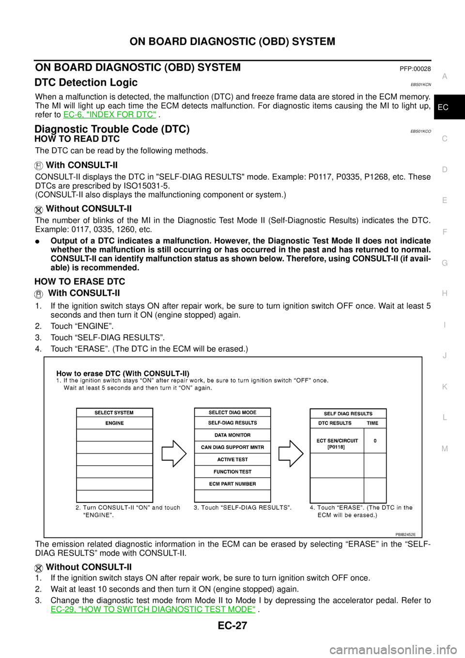
With CONSULT-II
1. If the ignition switch stays ON after repair work, be sure to turn ignition switch OFF once. Wait at least 5
seconds and then turn it ON (engine stopped) again.
2. Touch “ENGINE”.
3. Touch “SELF-DIAG RESULTS”.
4. Touch “ERASE”. (The DTC in the ECM will be erased.)
The emission related diagnostic information in the ECM can be erased by selecting “ERASE” in the “SELF-
DIAG RESULTS” mode with CONSULT-II.
Without CONSULT-II
1. If the ignition switch stays ON after repair work, be sure to turn ignition switch OFF once.
2. Wait at least 10 seconds and then turn it ON (engine stopped) again.
3. Change the diagnostic test mode from Mode II to Mode I by depressing the accelerator pedal. Refer to
EC-29, "
HOW TO SWITCH DIAGNOSTIC TEST MODE".
PBIB2452E
Page 1010 of 3171
EC-30
ON BOARD DIAGNOSTIC (OBD) SYSTEM
How to Erase Diagnostic Test Mode II (Self-diagnostic Results)
1. Set ECM in Diagnostic Test Mode II (Self-diagnostic results). Refer toEC-29, "How to Set Diagnostic Test
Mode II (Self-diagnostic Results)".
2. Fully depress the accelerator pedal and keep it for more than 10 seconds.
The emission-related diagnostic information has been erased from the backup memory in the ECM.
3. Fully release the accelerator pedal, and confirm the DTC 0000 is displayed.
DIAGNOSTIC TEST MODE I — BULB CHECK
In this mode, the MI on the combination meter should stay ON. If it remains OFF, check the bulb. Refer toEC-
354, "MI&DATA LINK CONNECTORS".
DIAGNOSTIC TEST MODE I — MALFUNCTION WARNING
These DTC numbers are clarified in Diagnostic Test Mode II (SELF-DIAGNOSTIC RESULTS)
DIAGNOSTIC TEST MODE II — SELF-DIAGNOSTIC RESULTS
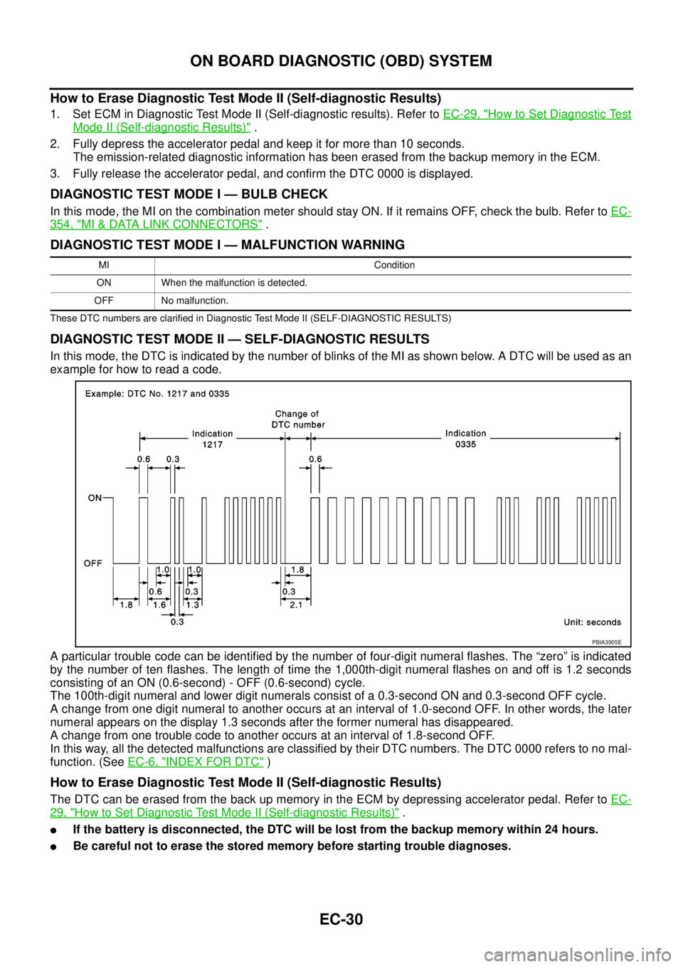
In this mode, the DTC is indicated by the number of blinks of the MI as shown below. A DTC will be used as an
example for how to read a code.
A particular trouble code can be identified by the number of four-digit numeral flashes. The “zero” is indicated
by the number of ten flashes. The length of time the 1,000th-digit numeral flashes on and off is 1.2 seconds
consisting of an ON (0.6-second) - OFF (0.6-second) cycle.
The 100th-digit numeral and lower digit numerals consist of a 0.3-second ON and 0.3-second OFF cycle.
A change from one digit numeral to another occurs at an interval of 1.0-second OFF. In other words, the later
numeral appears on the display 1.3 seconds after the former numeral has disappeared.
A change from one trouble code to another occurs at an interval of 1.8-second OFF.
In this way, all the detected malfunctions are classified by their DTC numbers. The DTC 0000 refers to no mal-
function. (SeeEC-6, "
INDEX FOR DTC")
How to Erase Diagnostic Test Mode II (Self-diagnostic Results)
The DTC can be erased from the back up memory in the ECM by depressing accelerator pedal. Refer toEC-
29, "How to Set Diagnostic Test Mode II (Self-diagnostic Results)".
lIf the battery is disconnected, the DTC will be lost from the backup memory within 24 hours.
lBe careful not to erase the stored memory before starting trouble diagnoses.
MI Condition
ON When the malfunction is detected.
OFF No malfunction.
PBIA3905E
Page 1044 of 3171
![NISSAN NAVARA 2005 Repair Workshop Manual EC-64
TROUBLE DIAGNOSIS
NOTE:
Any monitored item that does not match the vehicle being diagnosed is deleted from the display automatically.
ACTIVE TEST MODE
INT/M PRES SE [kPa]
lTurbocharger boost (de NISSAN NAVARA 2005 Repair Workshop Manual EC-64
TROUBLE DIAGNOSIS
NOTE:
Any monitored item that does not match the vehicle being diagnosed is deleted from the display automatically.
ACTIVE TEST MODE
INT/M PRES SE [kPa]
lTurbocharger boost (de](/manual-img/5/57362/w960_57362-1043.png)
EC-64
TROUBLE DIAGNOSIS
NOTE:
Any monitored item that does not match the vehicle being diagnosed is deleted from the display automatically.
ACTIVE TEST MODE
INT/M PRES SE [kPa]
lTurbocharger boost (determined by
the signal voltage from the turbo-
charger boost sensor) is displayed.
CYL COUNT [1/2/3/4]
lThe cylinder being injected is dis-
played.
1 ... Cylinder No.1 is injected.
2 ... Cylinder No.2 is injected.
3 ... Cylinder No.3 is injected.
4 ... Cylinder No.4 is injected.
SET SW
[ON/OFF]´
lIndicates [ON/OFF] condition from
SET/COAST switch signal.
RESUME/ACC SW
[ON/OFF]´
lIndicates [ON/OFF] condition from
RESUME/ACCEL switch signal.
CANCEL SW
[ON/OFF]´
lIndicates [ON/OFF] condition from
CANCEL switch signal.
MAIN SW
[ON/OFF]´
lIndicates [ON/OFF] condition from
MAIN switch signal.
ASCD APPLY [YES/NO]
lDisplaying ASCD application status
stored in ECM.
VDC APPLY [YES/NO]
lDisplaying ESP application status
stored in ECM.
AC PRESS SEN [V]
lThe signal voltage from the refrigerant
pressure sensor is displayed.
Voltage [V]
Voltage, frequency, duty cycle or pulse
width measured by the probe.Only “#” is displayed if item is unable to
be measured.
Figures with “#”s are temporary ones.
They are the same figures as an actual
piece of data which was just previously
measured. [Hz] or [%] Frequency
[msec],[Hz]or[%]
DUTY-HI
DUTY-LOW
PLS WIDTH-HI
PLS WIDTH-LOWMONITOR ITEMECM
INPUT
SIG-
NALMAIN
SIG-
NALSCONDITION SPECIFICATION
TEST ITEM CONDITION JUDGEMENT CHECK ITEM (REMEDY)
POWER BAL-
ANCE
lEngine: After warming up, idle the
engine.
lA/C switch: OFF
lShift lever: P or N (A/T), Neutral
(M/T)
lCut off each injector signal one at
a time using CONSULT-IIEngine runs rough or dies.
lHarness and connectors
lCompression
lFuel injector
COOLING FAN *
lIgnition switch: ON
lOperate the cooling fan at LOW,
HI speed and turn OFF using
CONSULT-II.Cooling fan moves at LOW, HI
speed and stops.lHarness and connector
lCooling fan motor
lCooling fan relay
ENG COOLANT
TEMP
lEngine: Return to the original
trouble condition
lChange the engine coolant tem-
perature using CONSULT-II.If trouble symptom disappears, see
CHECK ITEM.
lHarness and connectors
lEngine coolant temperature sen-
sor
lFuel injector
Page 1045 of 3171
TROUBLE DIAGNOSIS
EC-65
C
D
E
F
G
H
I
J
K
L
MA
EC
*: Leaving cooling fan OFF with CONSULT-II while engine is running may cause the engine to overheat.
REAL TIME DIAGNOSIS IN DATA MONITOR MODE
CONSULT-II has two kinds of triggers and they can be selected by touching “SETTING” in “DATA MONITOR”
mode.
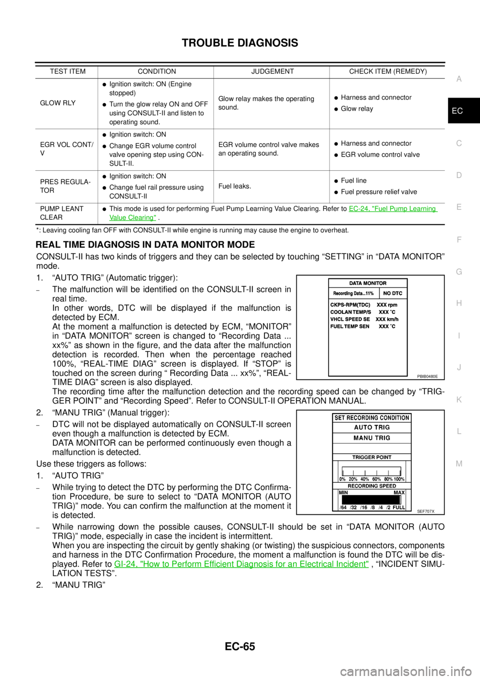
1. “AUTO TRIG” (Automatic trigger):
–The malfunction will be identified on the CONSULT-II screen in
real time.
In other words, DTC will be displayed if the malfunction is
detected by ECM.
At the moment a malfunction is detected by ECM, “MONITOR”
in “DATA MONITOR” screen is changed to “Recording Data ...
xx%” as shown in the figure, and the data after the malfunction
detection is recorded. Then when the percentage reached
100%, “REAL-TIME DIAG” screen is displayed. If “STOP” is
touched on the screen during “ Recording Data ... xx%”, “REAL-
TIME DIAG” screen is also displayed.
The recording time after the malfunction detection and the recording speed can be changed by “TRIG-
GER POINT” and “Recording Speed”. Refer to CONSULT-II OPERATION MANUAL.
2. “MANU TRIG” (Manual trigger):
–DTC will not be displayed automatically on CONSULT-II screen
even though a malfunction is detected by ECM.
DATA MONITOR can be performed continuously even though a
malfunction is detected.
Use these triggers as follows:
1. “AUTO TRIG”
–While trying to detect the DTC by performing the DTC Confirma-
tion Procedure, be sure to select to “DATA MONITOR (AUTO
TRIG)” mode. You can confirm the malfunction at the moment it
is detected.
–While narrowing down the possible causes, CONSULT-II should be set in “DATA MONITOR (AUTO
TRIG)” mode, especially in case the incident is intermittent.
When you are inspecting the circuit by gently shaking (or twisting) the suspicious connectors, components
and harness in the DTC Confirmation Procedure, the moment a malfunction is found the DTC will be dis-
played. Refer toGI-24, "
How to Perform Efficient Diagnosis for an Electrical Incident", “INCIDENT SIMU-
LATION TESTS”.
2. “MANU TRIG”
GLOW RLY
lIgnition switch: ON (Engine
stopped)
lTurn the glow relay ON and OFF
using CONSULT-II and listen to
operating sound.Glow relay makes the operating
sound.lHarness and connector
lGlow relay
EGR VOL CONT/
V
lIgnition switch: ON
lChange EGR volume control
valve opening step using CON-
SULT-II.EGR volume control valve makes
an operating sound.lHarness and connector
lEGR volume control valve
PRES REGULA-
TOR
lIgnition switch: ON
lChange fuel rail pressure using
CONSULT-IIFuel leaks.lFuel line
lFuel pressure relief valve
PUMP LEANT
CLEAR
lThis mode is used for performing Fuel Pump Learning Value Clearing. Refer toEC-24, "Fuel Pump Learning
Value Clearing". TEST ITEM CONDITION JUDGEMENT CHECK ITEM (REMEDY)
PBIB0480E
SEF707X
Page 1105 of 3171
DTC P0201 - P0204 FUEL INJECTOR
EC-125
C
D
E
F
G
H
I
J
K
L
MA
EC
DTC P0201 - P0204 FUEL INJECTORPFP:16600
Component DescriptionEBS01KFB
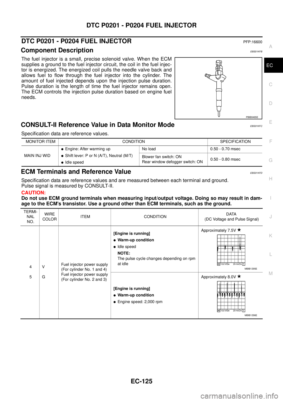
The fuel injector is a small, precise solenoid valve. When the ECM
supplies a ground to the fuel injector circuit, the coil in the fuel injec-
tor is energized. The energized coil pulls the needle valve back and
allows fuel to flow through the fuel injector into the cylinder. The
amount of fuel injected depends upon the injection pulse duration.
Pulse duration is the length of time the fuel injector remains open.
The ECM controls the injection pulse duration based on engine fuel
needs.
CONSULT-II Reference Value in Data Monitor ModeEBS01KFC
Specification data are reference values.
ECM Terminals and Reference ValueEBS01KFD
Specification data are reference values and are measured between each terminal and ground.
Pulse signal is measured by CONSULT-II.
CAUTION:
Do not use ECM ground terminals when measuring input/output voltage. Doing so may result in dam-
age to the ECM's transistor. Use a ground other than ECM terminals, such as the ground.
PBIB0465E
MONITOR ITEM CONDITION SPECIFICATION
MAIN INJ WID
lEngine: After warming up
lShift lever: P or N (A/T), Neutral (M/T)
lIdle speedNo load 0.50 - 0.70 msec
Blower fan switch: ON
Rear window defogger switch: ON0.50 - 0.80 msec
TERMI-
NAL
NO.WIRE
COLORITEM CONDITIONDATA
(DC Voltage and Pulse Signal)
4
5V
GFuel injector power supply
(For cylinder No. 1 and 4)
Fuel injector power supply
(For cylinder No. 2 and 3)[Engine is running]
lWarm-up condition
lIdle speed
NOTE:
The pulse cycle changes depending on rpm
at idleApproximately 7.5V
[Engine is running]
lWarm-up condition
lEngine speed: 2,000 rpmApproximately 8.0V
MBIB1295E
MBIB1296E
Page 1163 of 3171
DTC P0501 ASCD VEHICLE SPEED SENSOR
EC-183
C
D
E
F
G
H
I
J
K
L
MA
EC
DTC P0501 ASCD VEHICLE SPEED SENSORPFP:24810
Component DescriptionEBS01KHH
The ECM receives vehicle speed sensor signal via CAN communication line. It is sent from combination
meter. The ECM uses this signal for ASCD control. Refer toEC-355, "
AUTOMATIC SPEED CONTROL
DEVICE (ASCD)"for ASCD functions.
On Board Diagnosis LogicEBS01KHI
The MI will not light up for this self-diagnosis.
NOTE:
lIf DTC P0501 is displayed with DTC U1000 first perform the trouble diagnosis for DTC U1000. Refer
toEC-79, "
DTC U1000 CAN COMMUNICATION LINE".
lIf DTC P0501 is displayed with DTC P0606, first perform the trouble diagnosis for DTC P0606.
Refer toEC-215, "
DTC P0606 ECM".
DTC Confirmation ProcedureEBS01KHJ
CAUTION:
Always drive vehicle at a safe speed.
NOTE:
If DTC Confirmation Procedure has been previously conducted, always turn ignition switch OFF and wait at
least 10 seconds before conducting the next test.
TESTING CONDITION:
Step 3 may be conducted with the drive wheels lifted in the shop or by driving the vehicle. If a road test
is expected to be easier, it is unnecessary to lift the vehicle.
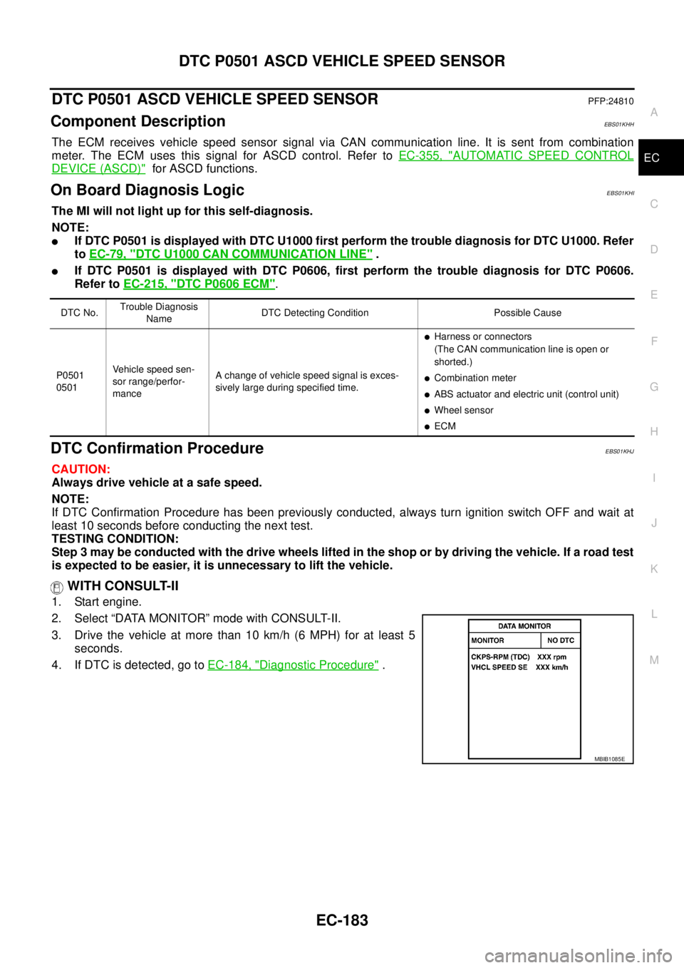
WITH CONSULT-II
1. Start engine.
2. Select “DATA MONITOR” mode with CONSULT-II.
3. Drive the vehicle at more than 10 km/h (6 MPH) for at least 5
seconds.
4. If DTC is detected, go toEC-184, "
Diagnostic Procedure".
DTC No.Trouble Diagnosis
NameDTC Detecting Condition Possible Cause
P0501
0501Vehicle speed sen-
sor range/perfor-
manceA change of vehicle speed signal is exces-
sively large during specified time.
lHarness or connectors
(The CAN communication line is open or
shorted.)
lCombination meter
lABS actuator and electric unit (control unit)
lWheel sensor
lECM
SEF058YMBIB1085E
Page 1217 of 3171
DTC P1268 - P1271 FUEL INJECTOR
EC-237
C
D
E
F
G
H
I
J
K
L
MA
EC
DTC P1268 - P1271 FUEL INJECTORPFP:16600
Component DescriptionEBS01KJ8
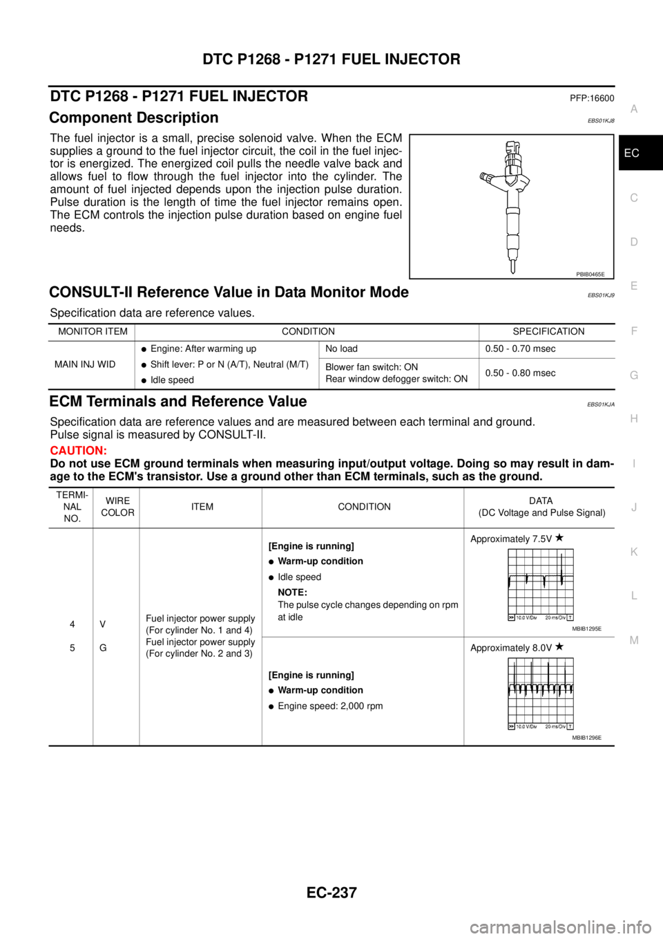
The fuel injector is a small, precise solenoid valve. When the ECM
supplies a ground to the fuel injector circuit, the coil in the fuel injec-
tor is energized. The energized coil pulls the needle valve back and
allows fuel to flow through the fuel injector into the cylinder. The
amount of fuel injected depends upon the injection pulse duration.
Pulse duration is the length of time the fuel injector remains open.
The ECM controls the injection pulse duration based on engine fuel
needs.
CONSULT-II Reference Value in Data Monitor ModeEBS01KJ9
Specification data are reference values.
ECM Terminals and Reference ValueEBS01KJA
Specification data are reference values and are measured between each terminal and ground.
Pulse signal is measured by CONSULT-II.
CAUTION:
Do not use ECM ground terminals when measuring input/output voltage. Doing so may result in dam-
age to the ECM's transistor. Use a ground other than ECM terminals, such as the ground.
PBIB0465E
MONITOR ITEM CONDITION SPECIFICATION
MAIN INJ WID
lEngine: After warming up
lShift lever: P or N (A/T), Neutral (M/T)
lIdle speedNo load 0.50 - 0.70 msec
Blower fan switch: ON
Rear window defogger switch: ON0.50 - 0.80 msec
TERMI-
NAL
NO.WIRE
COLORITEM CONDITIONDATA
(DC Voltage and Pulse Signal)
4
5V
GFuel injector power supply
(For cylinder No. 1 and 4)
Fuel injector power supply
(For cylinder No. 2 and 3)[Engine is running]
lWarm-up condition
lIdle speed
NOTE:
The pulse cycle changes depending on rpm
at idleApproximately 7.5V
[Engine is running]
lWarm-up condition
lEngine speed: 2,000 rpmApproximately 8.0V
MBIB1295E
MBIB1296E