2005 NISSAN NAVARA change time
[x] Cancel search: change timePage 2440 of 3171
TROUBLE DIAGNOSIS
MTC-53
C
D
E
F
G
H
I
K
L
MA
B
MTC
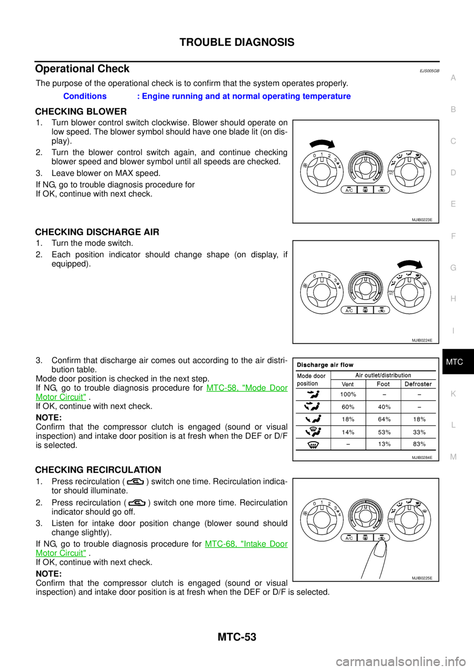
Operational CheckEJS005GB
The purpose of the operational check is to confirm that the system operates properly.
CHECKING BLOWER
1. Turn blower control switch clockwise. Blower should operate on
low speed. The blower symbol should have one blade lit (on dis-
play).
2. Turn the blower control switch again, and continue checking
blower speed and blower symbol until all speeds are checked.
3. Leave blower on MAX speed.
If NG, go to trouble diagnosis procedure for
If OK, continue with next check.
CHECKING DISCHARGE AIR
1. Turn the mode switch.
2. Each position indicator should change shape (on display, if
equipped).
3. Confirm that discharge air comes out according to the air distri-
bution table.
Mode door position is checked in the next step.
If NG, go to trouble diagnosis procedure forMTC-58, "
Mode Door
Motor Circuit".
If OK, continue with next check.
NOTE:
Confirm that the compressor clutch is engaged (sound or visual
inspection) and intake door position is at fresh when the DEF or D/F
is selected.
CHECKING RECIRCULATION
1. Press recirculation ( ) switch one time. Recirculation indica-
tor should illuminate.
2. Press recirculation ( ) switch one more time. Recirculation
indicator should go off.
3. Listen for intake door position change (blower sound should
change slightly).
If NG, go to trouble diagnosis procedure forMTC-68, "
Intake Door
Motor Circuit".
If OK, continue with next check.
NOTE:
Confirm that the compressor clutch is engaged (sound or visual
inspection) and intake door position is at fresh when the DEF or D/F is selected.Conditions : Engine running and at normal operating temperature
MJIB0223E
MJIB0224E
MJIB0284E
MJIB0225E
Page 2477 of 3171
MTC-90
TROUBLE DIAGNOSIS
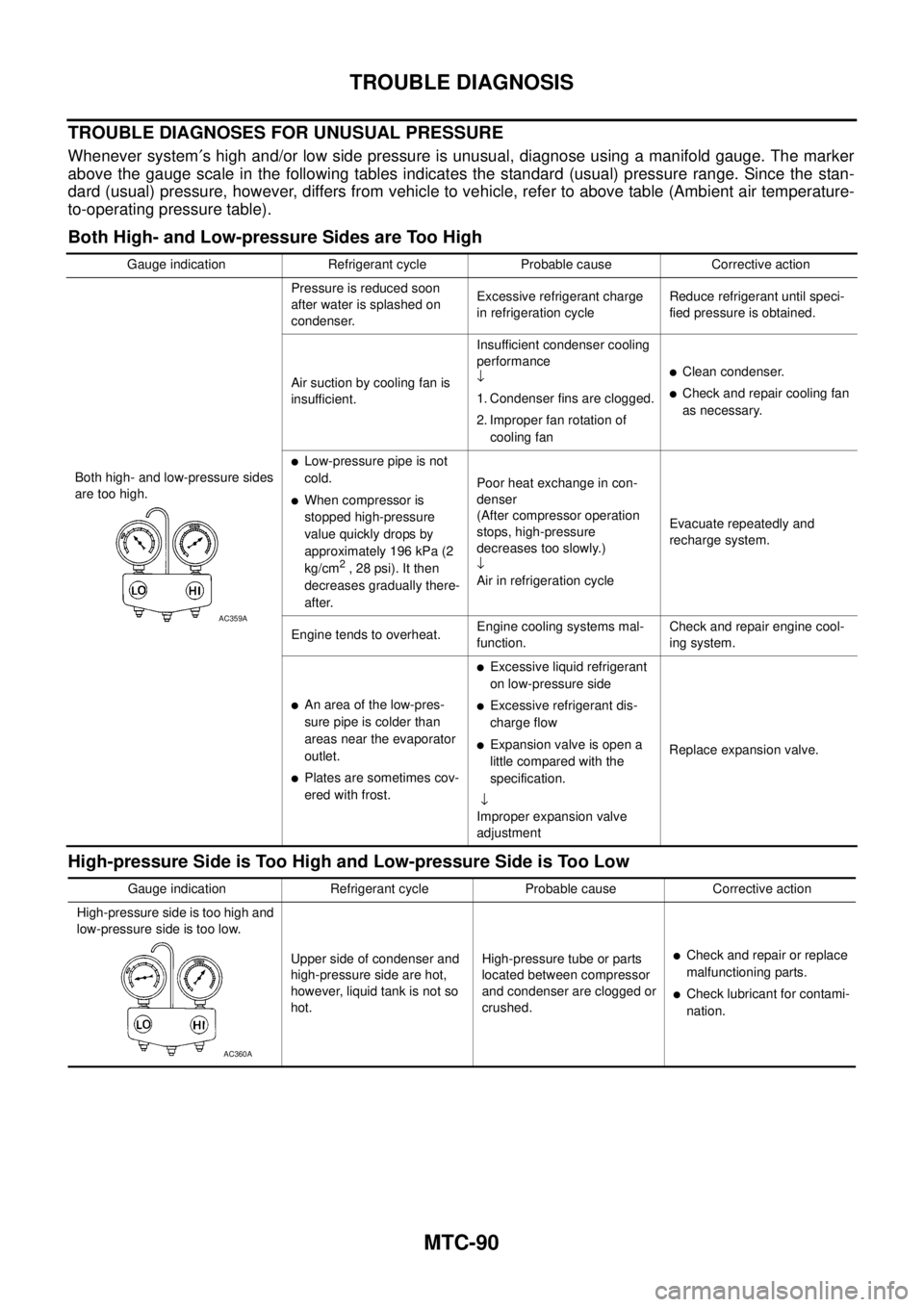
TROUBLE DIAGNOSES FOR UNUSUAL PRESSURE
Whenever system¢s high and/or low side pressure is unusual, diagnose using a manifold gauge. The marker
above the gauge scale in the following tables indicates the standard (usual) pressure range. Since the stan-
dard (usual) pressure, however, differs from vehicle to vehicle, refer to above table (Ambient air temperature-
to-operating pressure table).
Both High- and Low-pressure Sides are Too High
High-pressure Side is Too High and Low-pressure Side is Too Low
Gauge indication Refrigerant cycle Probable cause Corrective action
Both high- and low-pressure sides
are too high.Pressure is reduced soon
after water is splashed on
condenser.Excessive refrigerant charge
in refrigeration cycleReduce refrigerant until speci-
fied pressure is obtained.
Air suction by cooling fan is
insufficient.Insufficient condenser cooling
performance
¯
1. Condenser fins are clogged.
2. Improper fan rotation of
cooling fan
lClean condenser.
lCheck and repair cooling fan
as necessary.
lLow-pressure pipe is not
cold.
lWhen compressor is
stopped high-pressure
value quickly drops by
approximately 196 kPa (2
kg/cm
2,28psi).Itthen
decreases gradually there-
after.Poor heat exchange in con-
denser
(After compressor operation
stops, high-pressure
decreases too slowly.)
¯
Air in refrigeration cycleEvacuate repeatedly and
recharge system.
Engine tends to overheat.Engine cooling systems mal-
function.Check and repair engine cool-
ing system.
lAn area of the low-pres-
sure pipe is colder than
areas near the evaporator
outlet.
lPlates are sometimes cov-
ered with frost.
lExcessive liquid refrigerant
on low-pressure side
lExcessive refrigerant dis-
charge flow
lExpansion valve is open a
littlecomparedwiththe
specification.
¯
Improper expansion valve
adjustmentReplace expansion valve.
AC359A
Gauge indication Refrigerant cycle Probable cause Corrective action
High-pressure side is too high and
low-pressure side is too low.
Upper side of condenser and
high-pressure side are hot,
however, liquid tank is not so
hot.High-pressure tube or parts
located between compressor
and condenser are clogged or
crushed.
lCheck and repair or replace
malfunctioning parts.
lCheck lubricant for contami-
nation.
AC360A
Page 2684 of 3171
SQUEAK AND RATTLE TROUBLE DIAGNOSES
RF-7
C
D
E
F
G
H
J
K
L
MA
B
RF
TRUNK
Trunk noises are often caused by a loose jack or loose items put into the trunk by the owner.
In addition look for:
1. Trunk lid dumpers out of adjustment
2. Trunk lid striker out of adjustment
3. Trunk lid torsion bars knocking together
4. A loose license plate or bracket
Most of these incidents can be repaired by adjusting, securing or insulating the item(s) or component(s) caus-
ing the noise.
SUNROOF/HEADLINING
Noises in the sunroof/headlining area can often be traced to one of the following:
1. Sunroof lid, rail, linkage or seals making a rattle or light knocking noise
2. Sunvisor shaft shaking in the holder
3. Front or rear windshield touching headlining and squeaking
Again, pressing on the components to stop the noise while duplicating the conditions can isolate most of these
incidents. Repairs usually consist of insulating with felt cloth tape.
SEATS
When isolating seat noise it's important to note the position the seat is in and the load placed on the seat when
the noise is present. These conditions should be duplicated when verifying and isolating the cause of the
noise.
Cause of seat noise include:
1. Headrest rods and holder
2. A squeak between the seat pad cushion and frame
3. Rear seatback lock and bracket
These noises can be isolated by moving or pressing on the suspected components while duplicating the con-
ditions under which the noise occurs. Most of these incidents can be repaired by repositioning the component
or applying urethane tape to the contact area.
UNDERHOOD
Some interior noise may be caused by components under the hood or on the engine wall. The noise is then
transmitted into the passenger compartment.
Causes of transmitted underhood noise include:
1. Any component mounted to the engine wall
2. Components that pass through the engine wall
3. Engine wall mounts and connectors
4. Loose radiator mounting pins
5. Hood bumpers out of adjustment
6. Hood striker out of adjustment
These noises can be difficult to isolate since they cannot be reached from the interior of the vehicle. The best
method is to secure, move or insulate one component at a time and test drive the vehicle. Also, engine RPM
or load can be changed to isolate the noise. Repairs can usually be made by moving, adjusting, securing, or
insulating the component causing the noise.
Page 2705 of 3171

RFD-2
DIFFERENTIAL LOCK CONTROL UNIT ............ 42
DIFFERENTIAL LOCK MODE SWITCH ............. 42
DIFF LOCK INDICATOR LAMP ........................... 42
System Diagram ..................................................... 43
COMPONENTS FUNCTION DESCRIPTION ...... 43
CAN Communication .............................................. 43
SYSTEM DESCRIPTION .................................... 43
TROUBLE DIAGNOSIS ............................................ 44
Fail-safe Function ................................................... 44
How to Perform Trouble Diagnosis ......................... 44
BASIC CONCEPT ............................................... 44
Location of Electrical Parts ..................................... 45
Wiring Diagram — DIFLOC — ................................ 46
Trouble Diagnosis Chart for Symptoms .................. 48
Differential Lock Control Unit Input/Output Signal
Reference Values ................................................... 48
DIFFERENTIAL LOCK CONTROL UNIT
INSPECTION TABLE .......................................... 48
CONSULT-II Function (DIFF LOCK) ....................... 50
FUNCTION .......................................................... 50
CONSULT-II SETTING PROCEDURE ................ 50
SELF-DIAG RESULTS MODE ............................. 51
DATA MONITOR MODE ...................................... 53
TROUBLE DIAGNOSIS FOR SYSTEM .................... 54
Power Supply Circuit For Differential Lock Control
Unit ......................................................................... 54
CONSULT-II REFERENCE VALUE IN DATA
MONITOR MODE ................................................ 54
DIFFERENTIAL LOCK CONTROL UNIT TER-
MINALS AND REFERENCE VALUE ................... 54
DIAGNOSTIC PROCEDURE .............................. 55
Differential Lock Control Unit .................................. 56
DIAGNOSTIC PROCEDURE .............................. 56
Differential Lock Mode Switch ................................ 56
CONSULT-II REFERENCE VALUE IN DATA
MONITOR MODE ................................................ 56
DIFFERENTIAL LOCK CONTROL UNIT TER-
MINALS AND REFERENCE VALUE ................... 56
DIAGNOSTIC PROCEDURE .............................. 57
COMPONENT INSPECTION .............................. 59
Differential Lock Position Switch ............................. 60
CONSULT-II REFERENCE VALUE IN DATA
MONITOR MODE ................................................ 60
DIFFERENTIAL CONTROL UNIT TERMINALS
AND REFERENCE VALUE ................................. 60
DIAGNOSTIC PROCEDURE .............................. 61
COMPONENT INSPECTION .............................. 63
Differential Lock Solenoid Relay ............................. 63
CONSULT-II REFERENCE VALUE IN DATA
MONITOR MODE ................................................ 63DIAGNOSTIC PROCEDURE ............................... 63
Differential Lock Solenoid ....................................... 64
CONSULT-II REFERENCE VALUE IN DATA
MONITOR MODE ................................................ 64
DIFFERENTIAL LOCK CONTROL UNIT TER-
MINALS AND REFERENCE VALUE ................... 64
DIAGNOSTIC PROCEDURE ............................... 65
COMPONENT INSPECTION ............................... 68
ABS System ............................................................ 68
DIAGNOSTIC PROCEDURE ............................... 68
CAN Communication Line ....................................... 69
DIAGNOSTIC PROCEDURE ............................... 69
TROUBLE DIAGNOSIS FOR SYMPTOMS .............. 70
DIFF LOCK Indicator Lamp Does Not Turn ON ...... 70
DIAGNOSTIC PROCEDURE ............................... 70
DIFF LOCK Indicator Lamp Does Not Change ....... 73
DIAGNOSTIC PROCEDURE ............................... 73
DIFF LOCK Indicator Lamp Sometimes Flashes .... 74
DIAGNOSTIC PROCEDURE ............................... 74
DIFFERENTIAL LOCK CONTROL UNIT .................. 76
Removal and Installation ......................................... 76
REMOVAL ............................................................ 76
INSTALLATION .................................................... 76
FRONT OIL SEAL ..................................................... 77
Removal and Installation ......................................... 77
REMOVAL ............................................................ 77
INSTALLATION .................................................... 78
CARRIER COVER ..................................................... 80
Removal and Installation ......................................... 80
REMOVAL ............................................................ 80
INSTALLATION .................................................... 80
REAR FINAL DRIVE ASSEMBLY ............................. 81
Removal and Installation ......................................... 81
REMOVAL ............................................................ 81
INSTALLATION .................................................... 81
Disassembly and Assembly .................................... 82
COMPONENTS ................................................... 82
ASSEMBLY INSPECTION AND ADJUSTMENT...83
DISASSEMBLY .................................................... 86
INSPECTION AFTER DISASSEMBLY ................ 90
SELECTION ADJUSTING WASHERS ................ 90
ASSEMBLY .......................................................... 91
SERVICE DATA AND SPECIFICATIONS (SDS) ....100
General Specifications ..........................................100
Inspection and Adjustment ....................................100
PRELOAD TORQUE .........................................100
BACKLASH ........................................................100
COMPANION FLANGE RUNOUT .....................100
SELECTIVE PARTS ..........................................101
Page 2751 of 3171
![NISSAN NAVARA 2005 Repair Workshop Manual RFD-48
[WITH ELECTRONIC LOCKING DIFFERENTIAL]
TROUBLE DIAGNOSIS
Trouble Diagnosis Chart for Symptoms
EDS003AY
If DIFF LOCK indicator lamp does not turn ON after engine start, perform self-diagnosis. R NISSAN NAVARA 2005 Repair Workshop Manual RFD-48
[WITH ELECTRONIC LOCKING DIFFERENTIAL]
TROUBLE DIAGNOSIS
Trouble Diagnosis Chart for Symptoms
EDS003AY
If DIFF LOCK indicator lamp does not turn ON after engine start, perform self-diagnosis. R](/manual-img/5/57362/w960_57362-2750.png)
RFD-48
[WITH ELECTRONIC LOCKING DIFFERENTIAL]
TROUBLE DIAGNOSIS
Trouble Diagnosis Chart for Symptoms
EDS003AY
If DIFF LOCK indicator lamp does not turn ON after engine start, perform self-diagnosis. Refer toRFD-51, "SELF-DIAG RESULTSMODE".
Differential Lock Control Unit Input/Output Signal Reference ValuesEDS003AZ
DIFFERENTIAL LOCK CONTROL UNIT INSPECTION TABLE
Specifications with CONSULT-II
Symptom Condition Check itemReference
page
DIFF LOCK indicator lamp does not turn ON.
(DIFF LOCK indicator lamp check)Ignition switch: ONCAN communication line
RFD-70
Power supply and ground for differential
lock control unit
Combination meter
DIFF LOCK indicator lamp does not change.
lEngine running
lDifferential lock mode
switch: ONCombination meter
RFD-73Differential lock mode switch
CAN communication line
DIFF LOCK indicator lamp sometimes flashes.
lEngine running
lDifferential lock mode
switch: ONCombination meter
RFD-74Differential lock mode switch
Differential lock position switch
Differential inner parts
Monitor item [Unit] Content Condition Display value
BATTERY VOLT [V]Power supply voltage for
differential lock control unitIgnition switch: ON Battery voltage
4WD MODE [2H/4H/
4Lo]Condition of 4WD shift
switch4WD shift switch
(Engine running)2WD 2H
4H 4H
4LO 4Lo
VHCL S/SEN-R [km/h]
or [mph]Wheel speed
(Rear wheel right)Vehicle stopped 0 km/h (0 mph)
Vehicle running
CAUTION:
Check air pressure of tire under standard condition.Approximately
equal to the indi-
cation on speed-
ometer (Inside of
±10%)
VHCL S/SEN-L [km/h] or
[mph]Wheel speed
(Rear wheel left)Vehicle stopped 0 km/h (0 mph)
Vehicle running
CAUTION:
Check air pressure of tire under standard condition.Approximately
equal to the indi-
cation on speed-
ometer (Inside of
±10%)
VHCL S/SEN-RL [km/h]
or [mph]Wheel speed
(Average value of rear
wheel right and left)Vehicle stopped 0 km/h (0 mph)
Vehicle running
CAUTION:
Check air pressure of tire under standard condition.Approximately
equal to the indi-
cation on speed-
ometer (Inside of
±10%)
D-LOCK SW SIG [ON/
OFF]Condition of differential
lock mode switchDifferential lock mode switch: ON ON
Differential lock mode switch: OFF OFF
D-LOCK SIG [ON/OFF]Control status of differen-
tial lock
lVehicle stopped
lEngine running
l4WD shift switch: 4LODifferential lock mode
switch: ONON
Differential lock mode
switch: OFFOFF
Page 2854 of 3171
CHARGING SYSTEM
SC-21
C
D
E
F
G
H
I
J
L
MA
B
SC
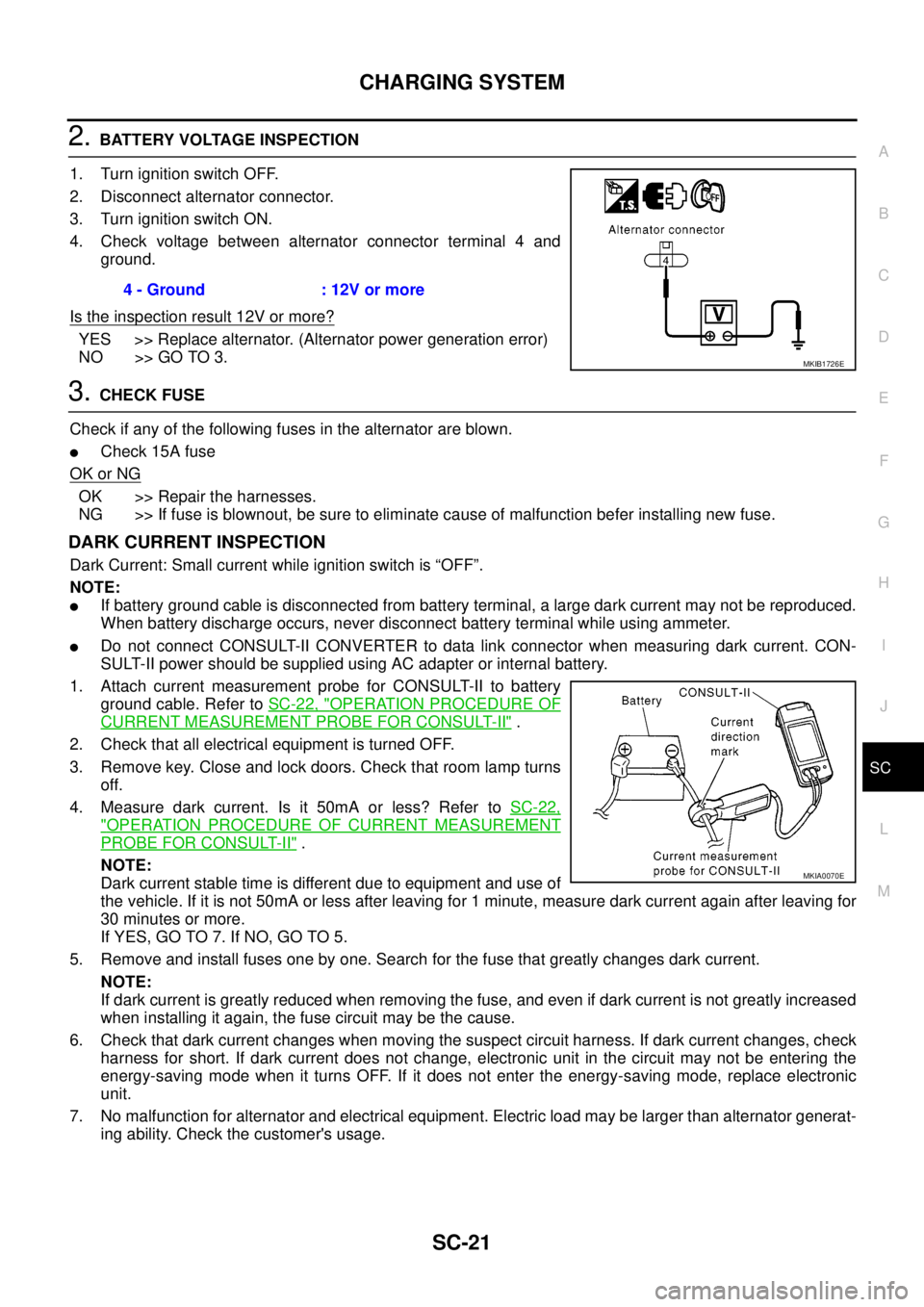
2.BATTERY VOLTAGE INSPECTION
1. Turn ignition switch OFF.
2. Disconnect alternator connector.
3. Turn ignition switch ON.
4. Check voltage between alternator connector terminal 4 and
ground.
Is the inspection result 12V or more?
YES >> Replace alternator. (Alternator power generation error)
NO >> GO TO 3.
3.CHECK FUSE
Check if any of the following fuses in the alternator are blown.
lCheck 15A fuse
OK or NG
OK >> Repair the harnesses.
NG >> If fuse is blownout, be sure to eliminate cause of malfunction befer installing new fuse.
DARK CURRENT INSPECTION
Dark Current: Small current while ignition switch is “OFF”.
NOTE:
lIf battery ground cable is disconnected from battery terminal, a large dark current may not be reproduced.
When battery discharge occurs, never disconnect battery terminal while using ammeter.
lDo not connect CONSULT-II CONVERTER to data link connector when measuring dark current. CON-
SULT-II power should be supplied using AC adapter or internal battery.
1. Attach current measurement probe for CONSULT-II to battery
ground cable. Refer toSC-22, "
OPERATION PROCEDURE OF
CURRENT MEASUREMENT PROBE FOR CONSULT-II".
2. Check that all electrical equipment is turned OFF.
3. Remove key. Close and lock doors. Check that room lamp turns
off.
4. Measure dark current. Is it 50mA or less? Refer toSC-22,
"OPERATION PROCEDURE OF CURRENT MEASUREMENT
PROBE FOR CONSULT-II".
NOTE:
Dark current stable time is different due to equipment and use of
the vehicle. If it is not 50mA or less after leaving for 1 minute, measure dark current again after leaving for
30 minutes or more.
If YES, GO TO 7. If NO, GO TO 5.
5. Remove and install fuses one by one. Search for the fuse that greatly changes dark current.
NOTE:
If dark current is greatly reduced when removing the fuse, and even if dark current is not greatly increased
when installing it again, the fuse circuit may be the cause.
6. Check that dark current changes when moving the suspect circuit harness. If dark current changes, check
harness for short. If dark current does not change, electronic unit in the circuit may not be entering the
energy-saving mode when it turns OFF. If it does not enter the energy-saving mode, replace electronic
unit.
7. No malfunction for alternator and electrical equipment. Electric load may be larger than alternator generat-
ing ability. Check the customer's usage.4 - Ground : 12V or more
MKIB1726E
MKIA0070E
Page 2878 of 3171
SQUEAK AND RATTLE TROUBLE DIAGNOSES
SE-7
C
D
E
F
G
H
J
K
L
MA
B
SE
TRUNK
Trunk noises are often caused by a loose jack or loose items put into the trunk by the owner.
In addition look for:
1. Trunk lid dumpers out of adjustment
2. Trunk lid striker out of adjustment
3. Trunk lid torsion bars knocking together
4. A loose license plate or bracket
Most of these incidents can be repaired by adjusting, securing or insulating the item(s) or component(s) caus-
ing the noise.
SUNROOF/HEADLINING
Noises in the sunroof/headlining area can often be traced to one of the following:
1. Sunroof lid, rail, linkage or seals making a rattle or light knocking noise
2. Sunvisor shaft shaking in the holder
3. Front or rear windshield touching headlining and squeaking
Again, pressing on the components to stop the noise while duplicating the conditions can isolate most of these
incidents. Repairs usually consist of insulating with felt cloth tape.
SEATS
When isolating seat noise it's important to note the position the seat is in and the load placed on the seat when
the noise is present. These conditions should be duplicated when verifying and isolating the cause of the
noise.
Cause of seat noise include:
1. Headrest rods and holder
2. A squeak between the seat pad cushion and frame
3. Rear seatback lock and bracket
These noises can be isolated by moving or pressing on the suspected components while duplicating the con-
ditions under which the noise occurs. Most of these incidents can be repaired by repositioning the component
or applying urethane tape to the contact area.
UNDERHOOD
Some interior noise may be caused by components under the hood or on the engine wall. The noise is then
transmitted into the passenger compartment.
Causes of transmitted underhood noise include:
1. Any component mounted to the engine wall
2. Components that pass through the engine wall
3. Engine wall mounts and connectors
4. Loose radiator mounting pins
5. Hood bumpers out of adjustment
6. Hood striker out of adjustment
These noises can be difficult to isolate since they cannot be reached from the interior of the vehicle. The best
method is to secure, move or insulate one component at a time and test drive the vehicle. Also, engine RPM
or load can be changed to isolate the noise. Repairs can usually be made by moving, adjusting, securing, or
insulating the component causing the noise.
Page 2925 of 3171
SRS-16
TROUBLE DIAGNOSIS
CONSULT-II Function (AIR BAG)
EHS001XK
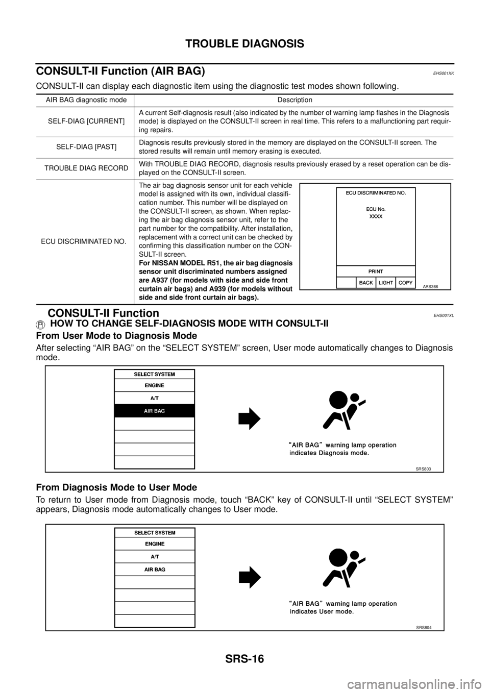
CONSULT-II can display each diagnostic item using the diagnostic test modes shown following.
CONSULT-II FunctionEHS001XL
HOW TO CHANGE SELF-DIAGNOSIS MODE WITH CONSULT-II
From User Mode to Diagnosis Mode
After selecting “AIR BAG” on the “SELECT SYSTEM” screen, User mode automatically changes to Diagnosis
mode.
From Diagnosis Mode to User Mode
To return to User mode from Diagnosis mode, touch “BACK” key of CONSULT-II until “SELECT SYSTEM”
appears, Diagnosis mode automatically changes to User mode.
AIR BAG diagnostic mode Description
SELF-DIAG [CURRENT]A current Self-diagnosis result (also indicated by the number of warning lamp flashes in the Diagnosis
mode) is displayed on the CONSULT-II screen in real time. This refers to a malfunctioning part requir-
ing repairs.
SELF-DIAG [PAST]Diagnosis results previously stored in the memory are displayed on the CONSULT-II screen. The
stored results will remain until memory erasing is executed.
TROUBLE DIAG RECORDWith TROUBLE DIAG RECORD, diagnosis results previously erased by a reset operation can be dis-
played on the CONSULT-II screen.
ECU DISCRIMINATED NO.The air bag diagnosis sensor unit for each vehicle
model is assigned with its own, individual classifi-
cation number. This number will be displayed on
the CONSULT-II screen, as shown. When replac-
ing the air bag diagnosis sensor unit, refer to the
part number for the compatibility. After installation,
replacement with a correct unit can be checked by
confirming this classification number on the CON-
SULT-II screen.
For NISSAN MODEL R51, the air bag diagnosis
sensor unit discriminated numbers assigned
are A937 (for models with side and side front
curtain air bags) and A939 (for models without
side and side front curtain air bags).
ARS366
SRS803
SRS804