2005 NISSAN NAVARA change time
[x] Cancel search: change timePage 2240 of 3171
INTERIOR ROOM LAMP
LT-157
C
D
E
F
G
H
I
J
L
MA
B
LT
CONSULT-II FunctionEKS00P99
CONSULT-II can display each diagnostic item using the diagnostic test mode shown following.
CONSULT-II OPERATION
CAUTION:
If CONSULT-II is used with no connection of CONSULT-II CONVERTER, malfunctions might be
detected in self-diagnosis depending on control unit which carries out CAN communication.
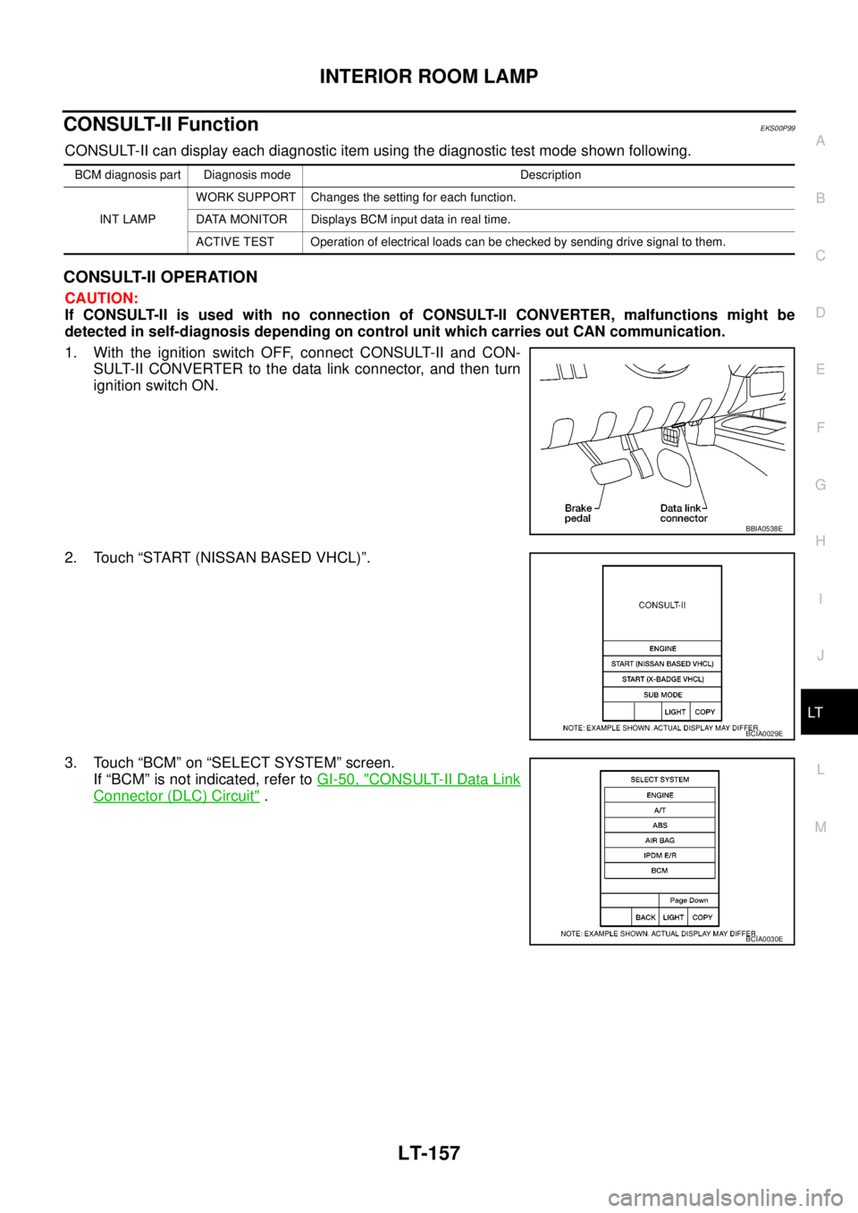
1. With the ignition switch OFF, connect CONSULT-II and CON-
SULT-II CONVERTER to the data link connector, and then turn
ignition switch ON.
2. Touch “START (NISSAN BASED VHCL)”.
3. Touch “BCM” on “SELECT SYSTEM” screen.
If “BCM” is not indicated, refer toGI-50, "
CONSULT-II Data Link
Connector (DLC) Circuit".
BCM diagnosis part Diagnosis mode Description
INT LAMPWORK SUPPORT Changes the setting for each function.
DATA MONITOR Displays BCM input data in real time.
ACTIVE TEST Operation of electrical loads can be checked by sending drive signal to them.
BBIA0538E
BCIA0029E
BCIA0030E
Page 2241 of 3171
LT-158
INTERIOR ROOM LAMP
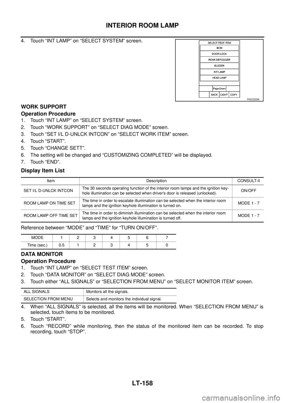
4. Touch “INT LAMP” on “SELECT SYSTEM” screen.
WORK SUPPORT
Operation Procedure
1. Touch “INT LAMP” on “SELECT SYSTEM” screen.
2. Touch “WORK SUPPORT” on “SELECT DIAG MODE” screen.
3. Touch “SET I/L D-UNLCK INTCON” on “SELECT WORK ITEM” screen.
4. Touch “START”.
5. Touch “CHANGE SETT”.
6. The setting will be changed and “CUSTOMIZING COMPLETED” will be displayed.
7. Touch “END”.
Display Item List
Reference between “MODE” and “TIME” for “TURN ON/OFF”.
DATA MONITOR
Operation Procedure
1. Touch “INT LAMP” on “SELECT TEST ITEM” screen.
2. Touch “DATA MONITOR” on “SELECT DIAG MODE” screen.
3. Touch either “ALL SIGNALS” or “SELECTION FROM MENU” on “SELECT MONITOR ITEM” screen.
4. When “ALL SIGNALS” is selected, all the items will be monitored. When “SELECTION FROM MENU” is
selected, touch items to be monitored.
5. Touch “START”.
6. Touch “RECORD” while monitoring, then the status of the monitored item can be recorded. To stop
recording, touch “STOP”.
PKIC0325E
Item Description CONSULT-II
SET I/L D-UNLCK INTCONThe 30 seconds operating function of the interior room lamps and the ignition key-
hole illumination can be selected when driver's door is released (unlocked).ON/OFF
ROOM LAMP ON TIME SETThe time in order to escalate illumination can be selected when the interior room
lamps and the ignition keyhole illumination is turned on.MODE 1 - 7
ROOM LAMP OFF TIME SETThe time in order to diminish illumination can be selected when the interior room
lamps and the ignition keyhole illumination is turned off.MODE 1 - 7
MODE 1 2 3 4 5 6 7
Time (sec.) 0.5 1 2 3 4 5 0
ALL SIGNALS Monitors all the signals.
SELECTION FROM MENU Selects and monitors the individual signal.
Page 2264 of 3171
ENGINE OIL
LU-7
C
D
E
F
G
H
I
J
K
L
MA
LU
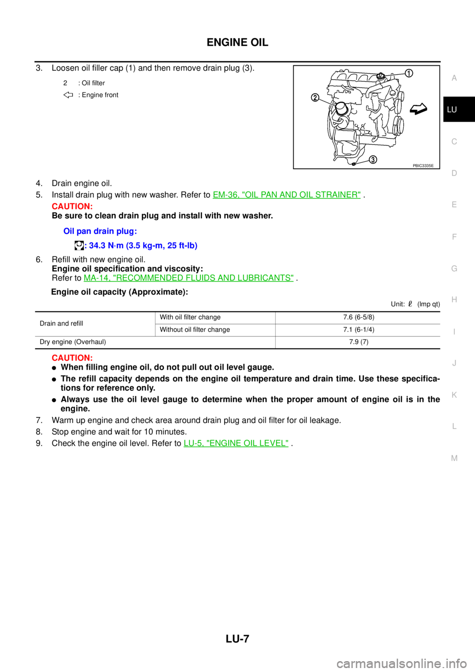
3. Loosen oil filler cap (1) and then remove drain plug (3).
4. Drain engine oil.
5. Install drain plug with new washer. Refer toEM-36, "
OIL PAN AND OIL STRAINER".
CAUTION:
Be sure to clean drain plug and install with new washer.
6. Refill with new engine oil.
Engine oil specification and viscosity:
Refer toMA-14, "
RECOMMENDED FLUIDS AND LUBRICANTS".
Engine oil capacity (Approximate):
Unit: (lmp qt)
CAUTION:
lWhen filling engine oil, do not pull out oil level gauge.
lThe refill capacity depends on the engine oil temperature and drain time. Use these specifica-
tions for reference only.
lAlways use the oil level gauge to determine when the proper amount of engine oil is in the
engine.
7. Warm up engine and check area around drain plug and oil filter for oil leakage.
8. Stop engine and wait for 10 minutes.
9. Check the engine oil level. Refer toLU-5, "
ENGINE OIL LEVEL".
2 : Oil filter
: Engine front
PBIC3335E
Oil pan drain plug:
: 34.3 N·m (3.5 kg-m, 25 ft-lb)
Drain and refillWith oil filter change 7.6 (6-5/8)
Without oil filter change 7.1 (6-1/4)
Dry engine (Overhaul)7.9 (7)
Page 2282 of 3171
GENERAL MAINTENANCE
MA-7
C
D
E
F
G
H
I
J
K
MA
B
MA
GENERAL MAINTENANCEPFP:00000
General MaintenanceELS001HT
General maintenance includes those items which should be checked during the normal day-to-day operation
of the vehicle. They are essential if the vehicle is to continue operating properly. The owners can perform the
checks and inspections themselves or they can have their NISSAN dealers do them for a nominal charge.
OUTSIDE THE VEHICLE
The maintenance items listed here should be performed from time to time, unless otherwise specified.
INSIDE THE VEHICLE
The maintenance items listed here should be checked on a regular basis, such as when performing periodic maintenance, cleaning the
vehicle, etc.
UNDER THE HOOD AND VEHICLE
The maintenance items listed here should be checked periodically e.g. each time you check the engine oil or refuel.Item Reference page
TiresCheck the pressure with a gauge periodically when at a service station, includ-
ing the spare, and adjust to the specified pressure if necessary. Check carefully
for damage, cuts or excessive wear.—
Windshield wiper
bladesCheck for cracks or wear if not functioning correctly. —
Doors and engine
hoodCheck that all doors, the engine hood, the trunk lid and back door operate prop-
erly. Also ensure that all latches lock securely. Lubricate if necessary. Make sure
that the secondary latch keeps the hood from opening when the primary latch is
released.
When driving in areas using road salt or other corrosive materials, check for
lubrication frequently.MA-39
,BL-12
Tire rotationTires should be rotated every 10,000 km (6,000 miles) for 2WD models and
every 5,000 km (3,000 miles) for 4WD models.MA-34
Item Reference page
LampsMake sure that the headlamps, stop lamps, tail lamps, turn signal lamps, and
other lamps are all operating properly and installed securely. Also check
headlamp aim.—
Warning lamps and
chimesMake sure that all warning lamps and buzzers/chimes are operating properly. —
Steering wheelCheck that it has the specified play.
Check for changes in the steering conditions, such as excessive free play, hard
steering or strange noises.
Free play: Less than 35 mm (1.38 in)—
Seat beltsCheck that all parts of the seat belt system (e.g. buckles, anchors, adjusters and
retractors) operate properly and smoothly, and are installed securely. Check the
belt webbing for cuts, fraying, wear or damage.MA-40
Item Reference page
Windshield washer
fluidCheck that there is adequate fluid in the tank. —
Engine coolant levelCheck the coolant level when the engine is cold.MA-19
(YD25DDTi)
Engine oil levelCheck the level after parking the vehicle (on level ground) and turning off the
engine.MA-25
(YD25DDTi)
Brake and clutch fluid
levelsMake sure that the brake and clutch fluid levels are between the “MAX” and
“MIN” lines on the reservoir.MA-28
,MA-35
BatteryCheck the fluid level in each cell. It should be between the “MAX” and “MIN”
lines.—
Page 2301 of 3171
MA-26
ENGINE MAINTENANCE
CAUTION:
Be sure to clean drain plug and install with new washer.
6. Refill with new engine oil.
Engine oil specification and viscosity:
Refer toMA-14, "
RECOMMENDED FLUIDS AND LUBRICANTS".
Engine oil capacity (Approximate):
Unit: (lmp qt)
CAUTION:
lWhen filling engine oil, do not pull out oil level gauge.
lThe refill capacity depends on the engine oil temperature and drain time. Use these specifica-
tions for reference only.
lAlways use the oil level gauge to determine when the proper amount of engine oil is in the
engine.
7. Warm up engine and check area around drain plug and oil filter for oil leakage.
8. Stop engine and wait for 10 minutes.
9. Check the engine oil level. Refer toLU-5, "
ENGINE OIL LEVEL".
Changing Oil FilterELS001JY
REMOVAL
1. Remove engine undercover middle.
2. Place a pan to catch the engine oil under the lower part of drain hose outlet before removing oil filter.
3. Using the oil filter wrench, remove oil filter.
CAUTION:
lBe careful not to get burned when engine and engine oil are hot.
lWhen removing, prepare a shop cloth to absorb any engine oil leakage or spillage.
lDo not allow engine oil to adhere to drive belts.
lCompletely wipe off any engine oil that adhere to engine and vehicle.
lOil filter is provided with a relief valve. Use Genuine NISSAN Oil Filter or equivalent.
INSTALLATION
1. Remove foreign materials adhering to the oil filter installation surface.
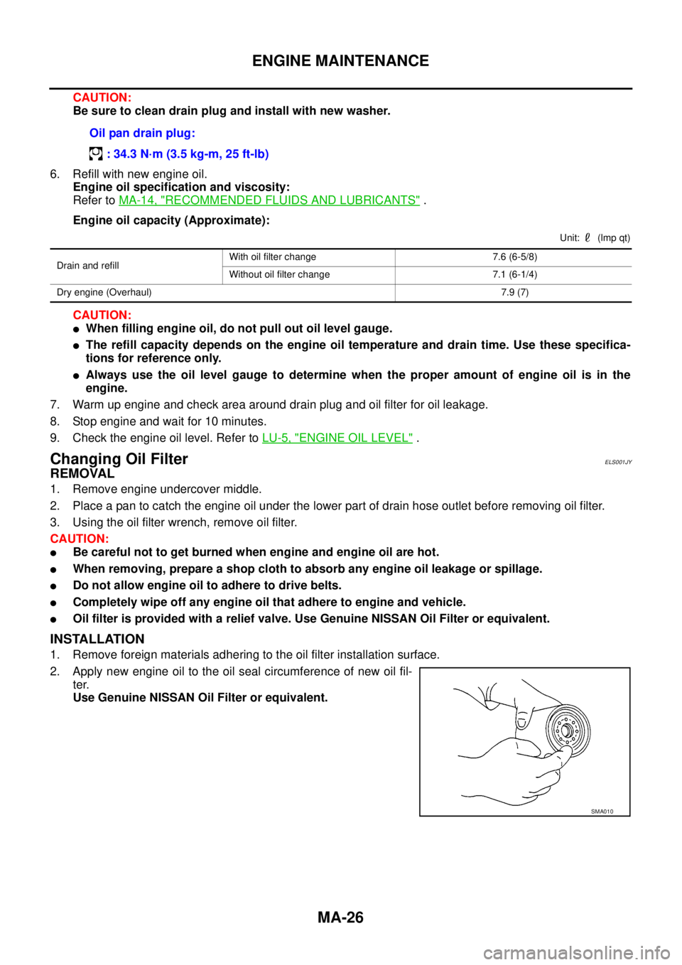
2. Apply new engine oil to the oil seal circumference of new oil fil-
ter.
Use Genuine NISSAN Oil Filter or equivalent.Oil pan drain plug:
: 34.3 N·m (3.5 kg-m, 25 ft-lb)
Drain and refillWith oil filter change 7.6 (6-5/8)
Without oil filter change 7.1 (6-1/4)
Dry engine (Overhaul)7.9 (7)
SMA010
Page 2401 of 3171
MTC-14
PRECAUTIONS
SERVICE COUPLERS
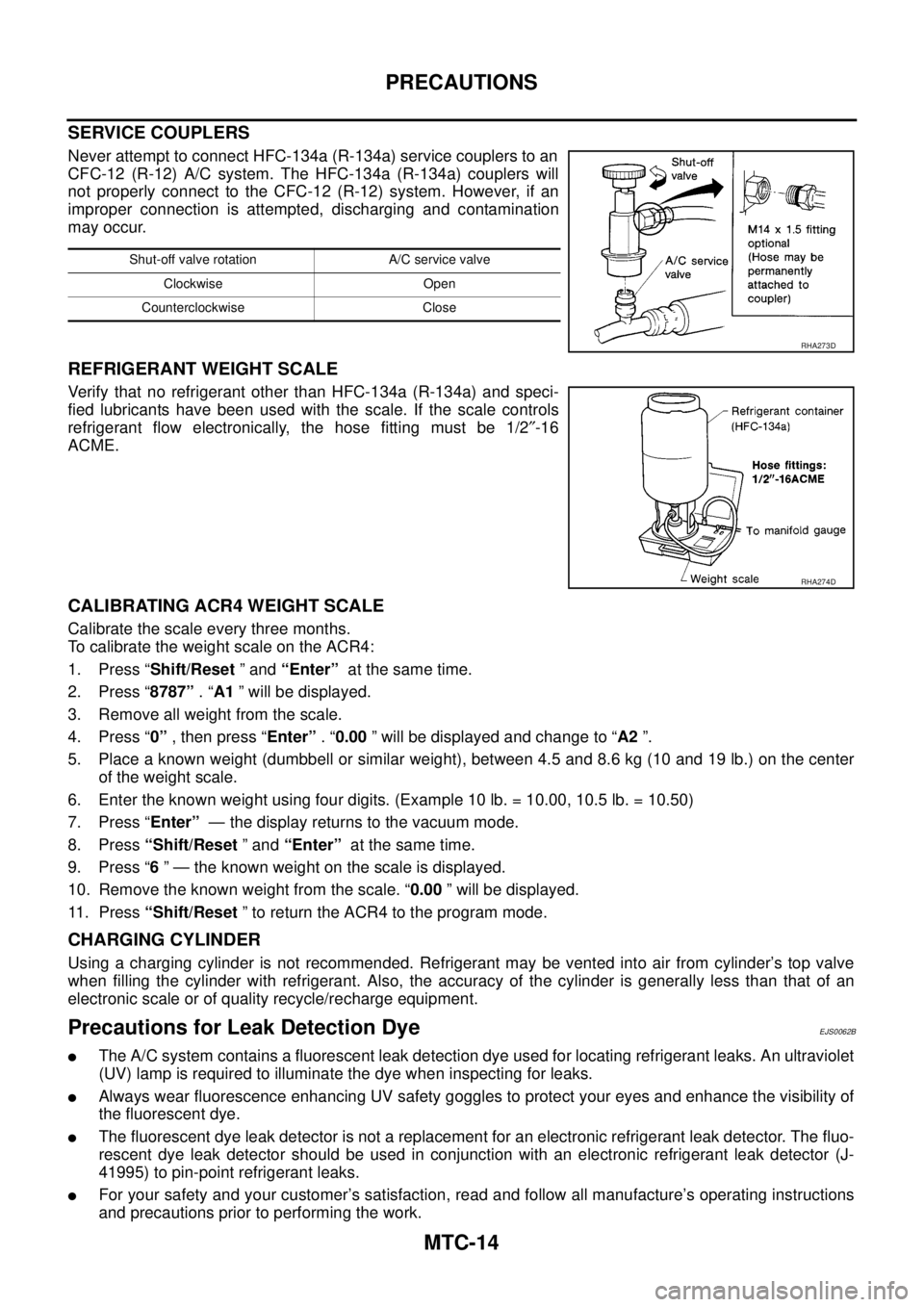
Never attempt to connect HFC-134a (R-134a) service couplers to an
CFC-12 (R-12) A/C system. The HFC-134a (R-134a) couplers will
not properly connect to the CFC-12 (R-12) system. However, if an
improper connection is attempted, discharging and contamination
may occur.
REFRIGERANT WEIGHT SCALE
Verify that no refrigerant other than HFC-134a (R-134a) and speci-
fied lubricants have been used with the scale. If the scale controls
refrigerant flow electronically, the hose fitting must be 1/2²-16
ACME.
CALIBRATING ACR4 WEIGHT SCALE
Calibrate the scale every three months.
To calibrate the weight scale on the ACR4:
1. Press “Shift/Reset”and“Enter”at the same time.
2. Press “8787”.“A1” will be displayed.
3. Remove all weight from the scale.
4. Press “0”, then press “Enter”.“0.00” will be displayed and change to “A2”.
5. Place a known weight (dumbbell or similar weight), between 4.5 and 8.6 kg (10 and 19 lb.) on the center
of the weight scale.
6. Enter the known weight using four digits. (Example 10 lb. = 10.00, 10.5 lb. = 10.50)
7. Press “Enter”— the display returns to the vacuum mode.
8. Press“Shift/Reset”and“Enter”at the same time.
9. Press “6” — the known weight on the scale is displayed.
10. Remove the known weight from the scale. “0.00” will be displayed.
11. Press“Shift/Reset” to return the ACR4 to the program mode.
CHARGING CYLINDER
Using a charging cylinder is not recommended. Refrigerant may be vented into air from cylinder’s top valve
when filling the cylinder with refrigerant. Also, the accuracy of the cylinder is generally less than that of an
electronic scale or of quality recycle/recharge equipment.
Precautions for Leak Detection DyeEJS0062B
lThe A/C system contains a fluorescent leak detection dye used for locating refrigerant leaks. An ultraviolet
(UV) lamp is required to illuminate the dye when inspecting for leaks.
lAlways wear fluorescence enhancing UV safety goggles to protect your eyes and enhance the visibility of
the fluorescent dye.
lThe fluorescent dye leak detector is not a replacement for an electronic refrigerant leak detector. The fluo-
rescent dye leak detector should be used in conjunction with an electronic refrigerant leak detector (J-
41995) to pin-point refrigerant leaks.
lFor your safety and your customer’s satisfaction, read and follow all manufacture’s operating instructions
and precautions prior to performing the work.
Shut-off valve rotation A/C service valve
Clockwise Open
Counterclockwise Close
RHA273D
RHA274D
Page 2411 of 3171
MTC-24
LUBRICANT
LUBRICANT
PFP:KLG00
Maintenance of Lubricant Quantity in CompressorEJS005FV
The lubricant in the compressor circulates through the system with the refrigerant. Add lubricant to compres-
sor when replacing any component or after a large refrigerant leakage has occurred. It is important to maintain
the specified amount.
If lubricant quantity is not maintained properly, the following malfunctions may result:
lLack of lubricant: May lead to a seized compressor
lExcessive lubricant: Inadequate cooling (thermal exchange interference)
LUBRICANT
Name: NISSAN A/C System Lubricant Type S (DH-PS)
Part number: KLH00-PAGS0
CHECKING AND ADJUSTING
CAUTION:
If excessive lubricant leakage is noted, do not perform the lubricant return operation.
Start the engine and set the following conditions:
test condition
lEngine speed: Idling to 1,200 rpm
lA/C switch: On
lBlower speed: Max. position
lTemp. control: Optional [Set so that intake air temperature is 25°to 30°C(77°to 86°F).]
lIntake position: Recirculation ( )
lPerform lubricant return operation for about ten minutes
Adjust the lubricant quantity according to the following table.
Lubricant Adjusting Procedure for Components Replacement Except Compressor
After replacing any of the following major components, add the correct amount of lubricant to the system.
Amount of lubricant to be added
l*1: If refrigerant leak is small, no addition of lubricant is needed.
Lubricant Adjustment Procedure for Compressor Replacement
1. Before connecting recovery/recycling equipment to vehicle, check recovery/recycling equipment gauges.
No refrigerant pressure should be displayed. If NG, recover refrigerant from equipment lines.
2. Discharge refrigerant into the refrigerant recovery/recycling equipment. Measure lubricant discharged into
the recovery/recycling equipment.
3. Drain the lubricant from the “old” (removed) compressor into a graduated container and recover the
amount of lubricant drained.
4. Drain the lubricant from the “new” compressor into a separate, clean container.
5. Measure an amount of new lubricant installed equal to amount drained from “old” compressor. Add this
lubricant to “new” compressor through the suction port opening.
6. Measure an amount of new lubricant equal to the amount recovered during discharging. Add this lubricant
to “new” compressor through the suction port opening.
7. If the liquid tank also needs to be replaced, add an additional 5 m (0.2 Imp fl oz) of lubricant at this time.
Do not add this 5 m (0.2 Imp fl oz) of lubricant if only replacing the compressor.
Part replacedLubricant to be added to system
Remarks
Amount of lubricant
m(Impfloz)
Evaporator 75 (2.6) —
Condenser 75 (2.6) —
Liquid tank 5 (0.2) Add if compressor is not replaced.
In case of refrigerant leak30 (1.1) Large leak
— Small leak *1
Page 2413 of 3171

MTC-26
AIR CONDITIONER CONTROL
AIR CONDITIONER CONTROL
PFP:27500
DescriptionEJS005FW
The front air control provides regulation of the vehicle's interior temperature. The system is based on the posi-
tion of the front air controls temperature switch selected by the driver. This is done by utilizing a microcom-
puter, also referred to as the front air control, which receives input signals from the following three sensors:
lIntake sensor
lPBR (Position Balanced Resistor).
The front air control uses these signals (including the set position of the temperature switch) to control:
lOutlet air volume
lAir temperature
lAir distribution
The front air control is used to select:
lOutlet air volume
lAir temperature/distribution
OperationEJS005FX
AIR MIX DOOR CONTROL
The air mix door is controlled so that in-vehicle temperature changed based on the position of the temperature
switch.
BLOWER SPEED CONTROL
Blower speed is controlled based on front blower switch settings.
When blower switch is turned, the blower motor starts and increases air flow volume each time the blower
switch is turned counterclockwise, and decreases air flow volume each time the blower switch is turned coun-
terclockwise.
When engine coolant temperature is low, the blower motor operation is delayed to prevent cool air from flow-
ing.
INTAKE DOORS CONTROL
The intake doors are controlled by the recirculation switch setting, and the mode (defroster) switch setting.
MODE DOOR CONTROL
The mode door is controlled by the position of the mode switch.
DEFROSTER DOOR CONTROL
The defroster door is controlled by: Turning the defroster dial to front defroster.