2005 NISSAN NAVARA change time
[x] Cancel search: change timePage 593 of 3171

SQUEAK AND RATTLE TROUBLE DIAGNOSES
BL-9
C
D
E
F
G
H
J
K
L
MA
B
BL
TRUNK
Trunk noises are often caused by a loose jack or loose items put into the trunk by the owner.
In addition look for:
1. Trunk lid dumpers out of adjustment
2. Trunk lid striker out of adjustment
3. Trunk lid torsion bars knocking together
4. A loose license plate or bracket
Most of these incidents can be repaired by adjusting, securing or insulating the item(s) or component(s) caus-
ing the noise.
SUNROOF/HEADLINING
Noises in the sunroof/headlining area can often be traced to one of the following:
1. Sunroof lid, rail, linkage or seals making a rattle or light knocking noise
2. Sunvisor shaft shaking in the holder
3. Front or rear windshield touching headlining and squeaking
Again, pressing on the components to stop the noise while duplicating the conditions can isolate most of these
incidents. Repairs usually consist of insulating with felt cloth tape.
SEATS
When isolating seat noise it's important to note the position the seat is in and the load placed on the seat when
the noise is present. These conditions should be duplicated when verifying and isolating the cause of the
noise.
Cause of seat noise include:
1. Headrest rods and holder
2. A squeak between the seat pad cushion and frame
3. Rear seatback lock and bracket
These noises can be isolated by moving or pressing on the suspected components while duplicating the con-
ditions under which the noise occurs. Most of these incidents can be repaired by repositioning the component
or applying urethane tape to the contact area.
UNDERHOOD
Some interior noise may be caused by components under the hood or on the engine wall. The noise is then
transmitted into the passenger compartment.
Causes of transmitted underhood noise include:
1. Any component mounted to the engine wall
2. Components that pass through the engine wall
3. Engine wall mounts and connectors
4. Loose radiator mounting pins
5. Hood bumpers out of adjustment
6. Hood striker out of adjustment
These noises can be difficult to isolate since they cannot be reached from the interior of the vehicle. The best
method is to secure, move or insulate one component at a time and test drive the vehicle. Also, engine RPM
or load can be changed to isolate the noise. Repairs can usually be made by moving, adjusting, securing, or
insulating the component causing the noise.
Page 619 of 3171
POWERDOORLOCKSYSTEM
BL-35
C
D
E
F
G
H
J
K
L
MA
B
BL
CONSULT-II Function (BCM)EIS00D80
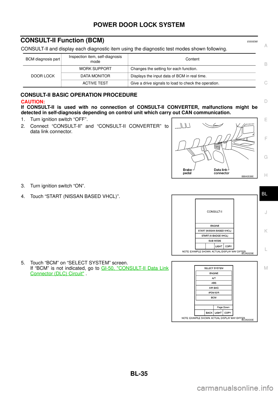
CONSULT-II and display each diagnostic item using the diagnostic test modes shown following.
CONSULT-II BASIC OPERATION PROCEDURE
CAUTION:
If CONSULT-II is used with no connection of CONSULT-II CONVERTER, malfunctions might be
detected in self-diagnosis depending on control unit which carry out CAN communication.
1. Turn ignition switch “OFF”.
2. Connect “CONSULT-II” and “CONSULT-II CONVERTER” to
data link connector.
3. Turn ignition switch “ON”.
4. Touch “START (NISSAN BASED VHCL)”.
5. Touch “BCM” on “SELECT SYSTEM” screen.
If “BCM” is not indicated, go toGI-50, "
CONSULT-II Data Link
Connector (DLC) Circuit".
BCM diagnosis partInspection item, self-diagnosis
modeContent
DOOR LOCKWORK SUPPORT Changes the setting for each function.
DATA MONITOR Displays the input data of BCM in real time.
ACTIVE TEST Give a drive signals to load to check the operation.
BBIA0538E
BCIA0029E
BCIA0030E
Page 654 of 3171
BL-70
POWER DOOR LOCK — SUPER LOCK —
CONSULT-II Function (BCM)
EIS00DX6
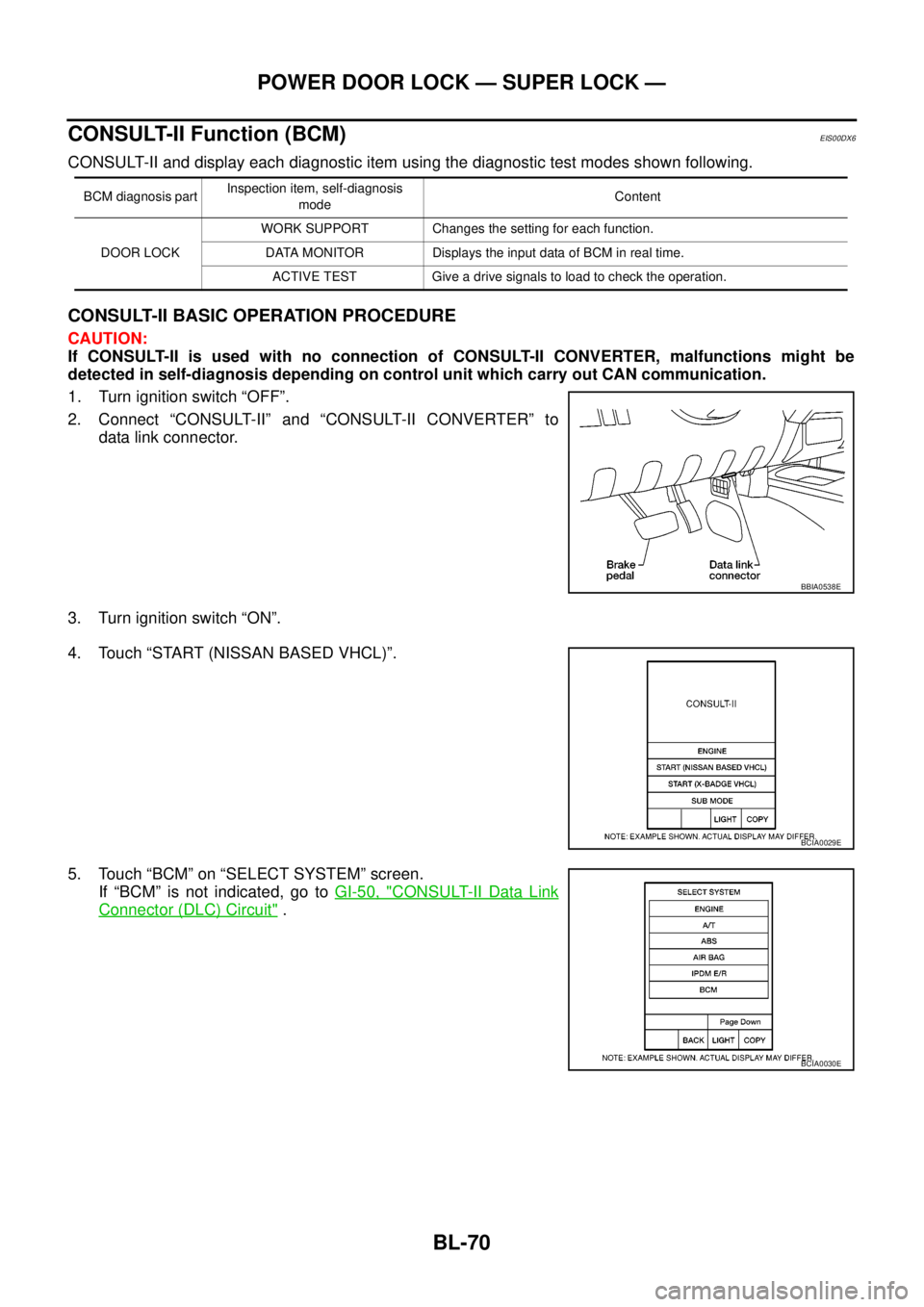
CONSULT-II and display each diagnostic item using the diagnostic test modes shown following.
CONSULT-II BASIC OPERATION PROCEDURE
CAUTION:
If CONSULT-II is used with no connection of CONSULT-II CONVERTER, malfunctions might be
detected in self-diagnosis depending on control unit which carry out CAN communication.
1. Turn ignition switch “OFF”.
2. Connect “CONSULT-II” and “CONSULT-II CONVERTER” to
data link connector.
3. Turn ignition switch “ON”.
4. Touch “START (NISSAN BASED VHCL)”.
5. Touch “BCM” on “SELECT SYSTEM” screen.
If “BCM” is not indicated, go toGI-50, "
CONSULT-II Data Link
Connector (DLC) Circuit".
BCM diagnosis partInspection item, self-diagnosis
modeContent
DOOR LOCKWORK SUPPORT Changes the setting for each function.
DATA MONITOR Displays the input data of BCM in real time.
ACTIVE TEST Give a drive signals to load to check the operation.
BBIA0538E
BCIA0029E
BCIA0030E
Page 675 of 3171

MULTI-REMOTE CONTROL SYSTEM
BL-91
C
D
E
F
G
H
J
K
L
MA
B
BL
System DescriptionEIS00DBE
INPUTS
Power is supplied at all times
lto BCM terminal 57
lthrough 50A fusible link (letterG, located in the fuse and fusible link box).
lto BCM terminal 41
lthrough 10A fuse [No. 21, located in the fuse block (J/B)].
When the key switch is ON (key is inserted in ignition key cylinder), power is supplied
lto BCM terminal 5
lthrough key switch terminals 2 and 1
lthrough 10A fuse [No. 22, located in the fuse block (J/B)].
When the ignition switch is ACC or ON, power is supplied
lto BCM terminal 4
lthrough 10A fuse [No. 4, located in the fuse block (J/B)].
When the ignition switch is ON or START, power is supplied
lto BCM terminal 3
lthrough 10A fuse [No. 1, located in the fuse block (J/B)].
When the front door switch (driver side) is ON (door is OPEN), ground is supplied
lto BCM terminal 15
lthrough front door switch (driver side) terminal 2
lto front door switch (driver side) case ground.
When the front door switch (passenger side) is ON (door is OPEN), ground is supplied
lto BCM terminal 14
lthrough front door switch (passenger side) terminal 2
lto front door switch (passenger side) case ground.
When the rear door switch LH is ON (door is OPEN), ground is supplied
lto BCM terminal 16
lthrough rear door switch LH terminal 2
lto rear door switch LH case ground.
When the rear door switch RH is ON (door is OPEN), ground is supplied
lto BCM terminal 12
lthrough rear door switch RH terminal 2
lto rear door switch RH case ground.
The multi-remote control system controls operation of the
lpowerdoorlock
linterior lamp and ignition keyhole illumination
lhazard reminder
lauto door lock operation
OPERATING PROCEDURE
Power Door Lock Operation
BCM receives a LOCK signal from keyfob. BCM locks all doors with input of LOCK signal from keyfob.
When an UNLOCK signal is sent from keyfob once, driver's door is unlocked.
Then, if an UNLOCK signal is sent from keyfob again within 5 seconds, all doors are unlocked.
Hazard Reminder
When the doors are locked or unlocked by keyfob, power is supplied to hazard warning lamp.
Hazard reminder does not operate if any door switches are ON (any doors are OPEN).
How to change hazard and horn reminder mode
Hazard and horn reminder can be changed using “WORK SUPPORT” mode in “MULTI ANSWER BACK SET”.
Refer toBL-102, "
CONSULT-II Function (BCM)".
Page 676 of 3171

BL-92
MULTI-REMOTE CONTROL SYSTEM
Auto Re-lock Function
The BCM is equipped with an auto re-lock function, when no further user action occurs after an full or partial
unlock, the doors will automatically re-lock after 2 minutes (default value).
The auto re-lock function will not be activated under the following state.
lKeyswitchisOn
lMechanical key is inserted
lAny door is opened
NOTE:
The 2 minutes timer of auto re-lock will be reset if unlock button from the key fob is pressed.
Auto relock function can be changed using “WORK SUPPORT” mode in “AUTO LOCK SET”.
Refer toBL-104, "
Work Support".
Room Lamp Operation
When the following conditions are met:
lcondition of room lamp switch is DOOR position;
ldoor switch OFF (when all the doors are closed);
With input of UNLOCK signal from keyfob multi-remote control system turns on interior lamp (for 30 seconds).
CAN Communication System DescriptionEIS00DBF
Refer toLAN-23, "CAN COMMUNICATION".
Page 805 of 3171
BRAKE BOOSTER
BR-19
C
D
E
G
H
I
J
K
L
MA
B
BR
BRAKE BOOSTERPFP:47200
On-Vehicle ServiceEFS005ST
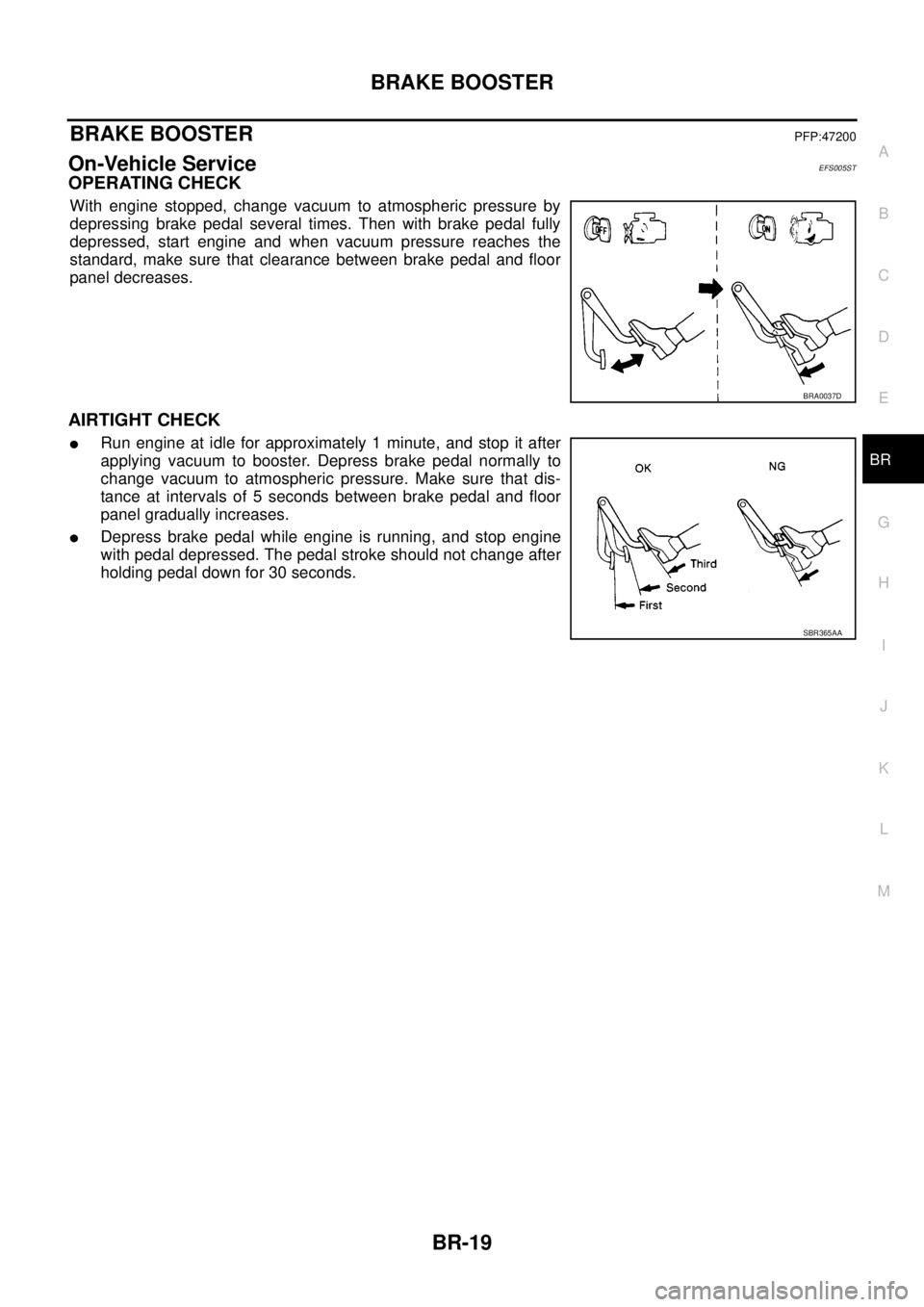
OPERATING CHECK
With engine stopped, change vacuum to atmospheric pressure by
depressing brake pedal several times. Then with brake pedal fully
depressed, start engine and when vacuum pressure reaches the
standard, make sure that clearance between brake pedal and floor
panel decreases.
AIRTIGHT CHECK
lRun engine at idle for approximately 1 minute, and stop it after
applying vacuum to booster. Depress brake pedal normally to
change vacuum to atmospheric pressure. Make sure that dis-
tance at intervals of 5 seconds between brake pedal and floor
panel gradually increases.
lDepress brake pedal while engine is running, and stop engine
with pedal depressed. The pedal stroke should not change after
holding pedal down for 30 seconds.
BRA0037D
SBR365AA
Page 915 of 3171
COMBINATION METERS
DI-5
C
D
E
F
G
H
I
J
L
MA
B
DI
FUEL GAUGE
The fuel gauge indicates the approximate fuel level in the fuel tank.
Combination meter reads a resistor signal from fuel level sensor unit.
Signal is supplied
lto combination meter terminal 9
lthrough fuel level sensor unit terminal 1 and 2
lfrom combination meter terminal 4.
ODO/TRIP METER
lABS actuator and electric unit (control unit) converses a pulse signal from wheel sensor to vehicle speed
signal, and transmits vehicle speed signal to combination meter with CAN communication.
lCombination meter uses the vehicle speed signal to calculate the mileage, and it displays.
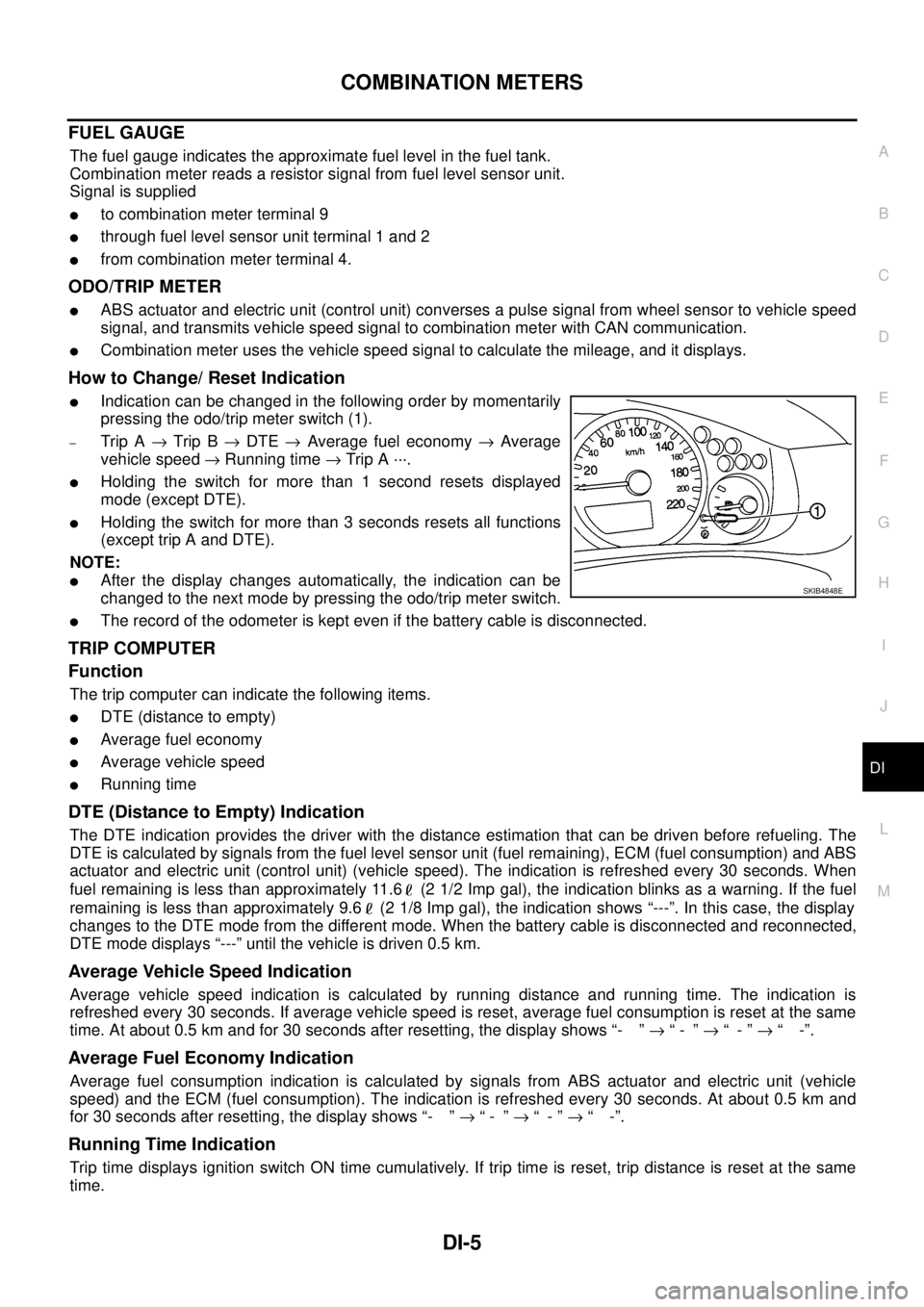
How to Change/ Reset Indication
lIndication can be changed in the following order by momentarily
pressing the odo/trip meter switch (1).
–Trip A®Trip B®DTE®Average fuel economy®Average
vehicle speed®Running time®Trip A ···.
lHolding the switch for more than 1 second resets displayed
mode (except DTE).
lHolding the switch for more than 3 seconds resets all functions
(except trip A and DTE).
NOTE:
lAfter the display changes automatically, the indication can be
changed to the next mode by pressing the odo/trip meter switch.
lThe record of the odometer is kept even if the battery cable is disconnected.
TRIP COMPUTER
Function
The trip computer can indicate the following items.
lDTE (distance to empty)
lAverage fuel economy
lAverage vehicle speed
lRunning time
DTE (Distance to Empty) Indication
The DTE indication provides the driver with the distance estimation that can be driven before refueling. The
DTE is calculated by signals from the fuel level sensor unit (fuel remaining), ECM (fuel consumption) and ABS
actuator and electric unit (control unit) (vehicle speed). The indication is refreshed every 30 seconds. When
fuel remaining is less than approximately 11.6 (2 1/2 Imp gal), the indication blinks as a warning. If the fuel
remaining is less than approximately 9.6 (2 1/8 Imp gal), the indication shows “---”. In this case, the display
changes to the DTE mode from the different mode. When the battery cable is disconnected and reconnected,
DTE mode displays “---” until the vehicle is driven 0.5 km.
Average Vehicle Speed Indication
Average vehicle speed indication is calculated by running distance and running time. The indication is
refreshed every 30 seconds. If average vehicle speed is reset, average fuel consumption is reset at the same
time. At about 0.5 km and for 30 seconds after resetting, the display shows “- ”®“- ”®“-”®“ -”.
Average Fuel Economy Indication
Average fuel consumption indication is calculated by signals from ABS actuator and electric unit (vehicle
speed) and the ECM (fuel consumption). The indication is refreshed every 30 seconds. At about 0.5 km and
for 30 seconds after resetting, the display shows “- ”®“- ”®“-”®“ -”.
Running Time Indication
Trip time displays ignition switch ON time cumulatively. If trip time is reset, trip distance is reset at the same
time.
SKIB4848E
Page 935 of 3171
COMBINATION METERS
DI-25
C
D
E
F
G
H
I
J
L
MA
B
DI
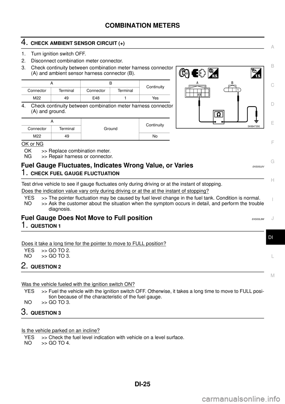
4.CHECK AMBIENT SENSOR CIRCUIT (+)
1. Turn ignition switch OFF.
2. Disconnect combination meter connector.
3. Check continuity between combination meter harness connector
(A) and ambient sensor harness connector (B).
4. Check continuity between combination meter harness connector
(A) and ground.
OK or NG
OK >> Replace combination meter.
NG >> Repair harness or connector.
Fuel Gauge Fluctuates, Indicates Wrong Value, or VariesEKS00L8V
1.CHECK FUEL GAUGE FLUCTUATION
Test drive vehicle to see if gauge fluctuates only during driving or at the instant of stopping.
Does the indication value vary only during driving or at the at the instant of stopping?
YES >> The pointer fluctuation may be caused by fuel level change in the fuel tank. Condition is normal.
NO >> Ask the customer about the situation when the symptom occurs in detail, and perform the trouble
diagnosis.
Fuel Gauge Does Not Move to Full positionEKS00L8W
1.QUESTION 1
Does it take a long time for the pointer to move to FULL position?
YES >> GO TO 2.
NO >> GO TO 3.
2.QUESTION 2
Was the vehicle fueled with the ignition switch ON?
YES >> Fuel the vehicle with the ignition switch OFF. Otherwise, it takes a long time to move to FULL posi-
tion because of the characteristic of the fuel gauge.
NO >> GO TO 3.
3.QUESTION 3
Isthevehicleparkedonanincline?
YES >> Check the fuel level indication with vehicle on a level surface.
NO >> GO TO 4.
AB
Continuity
Connector Terminal Connector Terminal
M22 49 E48 1 Yes
A
GroundContinuity
Connector Terminal
M22 49 No
SKIB4735E