Page 2926 of 3171
![NISSAN NAVARA 2005 Repair Workshop Manual TROUBLE DIAGNOSIS
SRS-17
C
D
E
F
G
I
J
K
L
MA
B
SRS
HOW TO ERASE SELF-DIAGNOSIS RESULTS
l“SELF-DIAG [CURRENT]”
A current self-diagnosis result is displayed on the CONSULT-II
screen in real time.
A NISSAN NAVARA 2005 Repair Workshop Manual TROUBLE DIAGNOSIS
SRS-17
C
D
E
F
G
I
J
K
L
MA
B
SRS
HOW TO ERASE SELF-DIAGNOSIS RESULTS
l“SELF-DIAG [CURRENT]”
A current self-diagnosis result is displayed on the CONSULT-II
screen in real time.
A](/manual-img/5/57362/w960_57362-2925.png)
TROUBLE DIAGNOSIS
SRS-17
C
D
E
F
G
I
J
K
L
MA
B
SRS
HOW TO ERASE SELF-DIAGNOSIS RESULTS
l“SELF-DIAG [CURRENT]”
A current self-diagnosis result is displayed on the CONSULT-II
screen in real time.
After the malfunction is repaired completely, no malfunction is
detected on “SELF-DIAG [CURRENT]”.
l“SELF-DIAG [PAST]”
Return to the “SELF-DIAG [CURRENT]” CONSULT-II screen by
touching “BACK” key of CONSULT-II and select “SELF-DIAG
[PAST]” in SELECT DIAG MODE. Touch “ERASE” in “SELF-
DIAG [PAST]” mode.
NOTE:
If the memory of the malfunction in “SELF-DIAG [PAST]” is
not erased, the User mode will continue to show the system
malfunction by the operation of the warning lamp even if
the malfunction is repaired completely.
l“TROUBLE DIAG RECORD”
The memory of “TROUBLE DIAG RECORD” cannot be erased.
Self-Diagnosis Function (Without CONSULT-II)EHS001XM
lThe reading of these results is accomplished using one of two modes — “User mode” and “Diagnosis
mode”.
lAfter a malfunction is repaired, turn the ignition switch OFF for at least one second, then back ON. Diag-
nosis mode returns to the User mode. At that time, the self-diagnostic result is cleared.
HOW TO CHANGE SELF-DIAGNOSIS MODE
SRS701
SRS702
SHIA0183E
Page 3005 of 3171

TF-38
TROUBLE DIAGNOSIS
Trouble Diagnosis Chart for Symptoms
EDS0031U
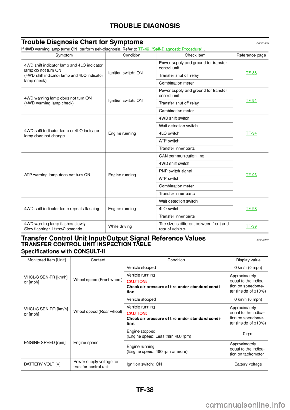
If 4WD warning lamp turns ON, perform self-diagnosis. Refer toTF-49, "Self-Diagnostic Procedure".
Transfer Control Unit Input/Output Signal Reference ValuesEDS0031V
TRANSFER CONTROL UNIT INSPECTION TABLE
Specifications with CONSULT-II
Symptom Condition Check item Reference page
4WD shift indicator lamp and 4LO indicator
lamp do not turn ON
(4WD shift indicator lamp and 4LO indicator
lamp check)Ignition switch: ONPower supply and ground for transfer
control unit
TF-88
Transfer shut off relay
Combination meter
4WD warning lamp does not turn ON
(4WD warning lamp check)Ignition switch: ONPower supply and ground for transfer
control unit
TF-91
Transfer shut off relay
Combination meter
4WD shift indicator lamp or 4LO indicator
lamp does not changeEngine running4WD shift switch
TF-94
Wait detection switch
4LO switch
AT P s w i t c h
Transfer inner parts
ATP warning lamp does not turn ON Engine runningCAN communication line
TF-96
4WD shift switch
PNP switch signal
AT P s w i t c h
Combination meter
Transfer inner parts
4WD shift indicator lamp repeats flashing Engine runningWait detection switch
TF-98
4LO switch
Transfer inner parts
4WD warning lamp flashes slowly
Slow flashing: 1 time/2 secondsWhile drivingTire size is different between front and
rear of vehicle.TF-99
Monitored item [Unit] Content Condition Display value
VHCL/S SEN·FR [km/h]
or [mph]Wheel speed (Front wheel)Vehicle stopped 0 km/h (0 mph)
Vehicle running
CAUTION:
Check air pressure of tire under standard condi-
tion.Approximately
equal to the indica-
tion on speedome-
ter (Inside of±10%)
VHCL/S SEN·RR [km/h]
or [mph]Wheel speed (Rear wheel)Vehicle stopped 0 km/h (0 mph)
Vehicle running
CAUTION:
Check air pressure of tire under standard condi-
tion.Approximately
equal to the indica-
tion on speedome-
ter (Inside of±10%)
ENGINE SPEED [rpm] Engine speedEngine stopped
(Engine speed: Less than 400 rpm)0rpm
Engine running
(Engine speed: 400 rpm or more)Approximately
equal to the indica-
tion on tachometer
BATTERY VOLT [V]Power supply voltage for
transfer control unitIgnition switch: ON Battery voltage
Page 3119 of 3171
WW-8
FRONT WIPER AND WASHER SYSTEM
COMBINATION SWITCH READING FUNCTION
Description
lBCM reads combination switch status, and controls related systems such as headlamps and wipers,
according to the results.
lBCM reads information for a maximum of 20 switches by combining 5 output terminals (OUTPUT 1-5) and
5 input terminals (INPUT 1-5).
Operation Description
lBCM activates transistors of output terminals (OUTPUT 1-5) periodically, and allows current to flow in
turn.
lIf any (1 or more) switches are turned ON, the circuit of output terminals (OUTPUT 1-5) and input termi-
nals (INPUT 1-5) becomes active.
lAt this time, transistors of output terminals (OUTPUT 1-5) are activated to allow current to flow. When volt-
age of the input terminal (INPUT 1-5) corresponding to that switch changes, the interface in the BCM
detects a voltage change, and the BCM determines that the switch is ON.
PKIC1724E
Page 3120 of 3171
FRONT WIPER AND WASHER SYSTEM
WW-9
C
D
E
F
G
H
I
J
L
MA
B
WW
BCM - Operation Table of Combination Switches
lBCM reads operation status of the combination switch using combinations shown in the table below.
Sample Operation: (When Wiper Switch is Turned ON)
lWhen the wiper switch is turned ON, contact in the combination switch turns ON. At this time if OUTPUT 1
transistor is activated, the BCM detects that voltage changes in INPUT 3.
lWhen the OUTPUT 1 transistor is ON, the BCM detects that voltage changes in INPUT 3, and judges that
front wiper low is ON. Then the BCM sends a front wiper request signal (LO) to the IPDM E/R using CAN
communication.
lWhen OUTPUT 1 transistor is activated again, BCM detects that voltage changes in INPUT 3, and recog-
nizes that the wiper switch is continuously ON.
PKIC0420E
PKIC1726E
Page 3129 of 3171

WW-18
FRONT WIPER AND WASHER SYSTEM
CONSULT-II Function (BCM)
EKS00P53
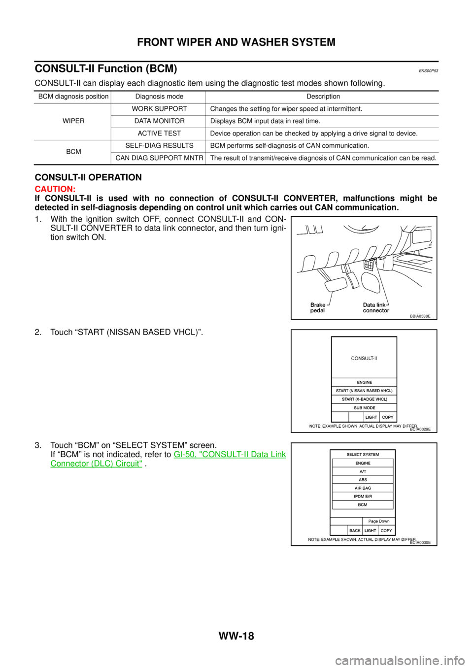
CONSULT-II can display each diagnostic item using the diagnostic test modes shown following.
CONSULT-II OPERATION
CAUTION:
If CONSULT-II is used with no connection of CONSULT-II CONVERTER, malfunctions might be
detected in self-diagnosis depending on control unit which carries out CAN communication.
1. With the ignition switch OFF, connect CONSULT-II and CON-
SULT-II CONVERTER to data link connector, and then turn igni-
tion switch ON.
2. Touch “START (NISSAN BASED VHCL)”.
3. Touch “BCM” on “SELECT SYSTEM” screen.
If “BCM” is not indicated, refer toGI-50, "
CONSULT-II Data Link
Connector (DLC) Circuit".
BCM diagnosis position Diagnosis mode Description
WIPERWORK SUPPORT Changes the setting for wiper speed at intermittent.
DATA MONITOR Displays BCM input data in real time.
ACTIVE TEST Device operation can be checked by applying a drive signal to device.
BCMSELF-DIAG RESULTS BCM performs self-diagnosis of CAN communication.
CAN DIAG SUPPORT MNTR The result of transmit/receive diagnosis of CAN communication can be read.
BBIA0538E
BCIA0029E
BCIA0030E
Page 3144 of 3171

FRONT WIPER AND WASHER SYSTEM
WW-33
C
D
E
F
G
H
I
J
L
MA
B
WW
Front Wiper Intermittent Operation Switch Position Cannot Be AdjustedEKS00P5B
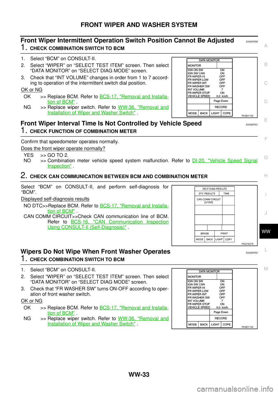
1.CHECK COMBINATION SWITCH TO BCM
1. Select “BCM” on CONSULT-II.
2. Select “WIPER” on “SELECT TEST ITEM” screen. Then select
“DATA MONITOR” on “SELECT DIAG MODE” screen.
3. Check that “INT VOLUME” changes in order from 1 to 7 accord-
ing to operation of the intermittent switch dial position.
OK or NG
OK >> Replace BCM. Refer toBCS-17, "Removal and Installa-
tion of BCM".
NG >> Replace wiper switch. Refer toWW-36, "
Removal and
Installation of Wiper and Washer Switch".
Front Wiper Interval Time Is Not Controlled by Vehicle SpeedEKS00P5C
1.CHECK FUNCTION OF COMBINATION METER
Confirm that speedometer operates normally.
Does the front wiper operate normally?
YES >> GO TO 2.
NO >> Combination meter vehicle speed system malfunction. Refer toDI-20, "
Vehicle Speed Signal
Inspection".
2.CHECK CAN COMMUNICATION BETWEEN BCM AND COMBINATION METER
Select “BCM” on CONSULT-II, and perform self-diagnosis for
“BCM”.
Displayed self
-diagnosis results
NO DTC>>Replace BCM. Refer toBCS-17, "Removal and Installa-
tion of BCM".
CAN COMM CIRCUIT>>Check CAN communication line of BCM.
Refer toBCS-16, "
CAN Communication Inspection
Using CONSULT-II (Self-Diagnosis)".
Wipers Do Not Wipe When Front Washer OperatesEKS00P5D
1.CHECK COMBINATION SWITCH TO BCM
1. Select “BCM” on CONSULT-II.
2. Select “WIPER” on “SELECT TEST ITEM” screen. Then select
“DATA MONITOR” on “SELECT DIAG MODE” screen.
3. Check that “FR WASHER SW” turns ON-OFF according to oper-
ation of front washer switch.
OK or NG
OK >> Replace BCM. Refer toBCS-17, "Removal and Installa-
tion of BCM".
NG >> Replace wiper switch. Refer toWW-36, "
Removal and
Installation of Wiper and Washer Switch".
PKIB0110E
PKIA7627E
PKIB0110E