2005 NISSAN NAVARA change time
[x] Cancel search: change timePage 495 of 3171

SYSTEM DESCRIPTION
AV-7
C
D
E
F
G
H
I
J
L
MA
B
AV
GPS (Global Positioning System)
GPS (Global Positioning System) was developed for and is con-
trolled by the US Department of Defense. The system utilizes GPS
satellites (NAVSTAR), sending out radio waves while flying on an
orbit around the earth at an altitude of approximately 21,000 km
(13,000 miles).
The GPS receiver calculates the vehicle's position in three dimen-
sions (latitude/longitude/altitude) according to the time lag of the
radio waves received from four or more GPS satellites (three-dimen-
sional positioning). If radio waves were received only from three
GPS satellites, the GPS receiver calculates the vehicle's position in
two dimensions (latitude/longitude), utilizing the altitude data calcu-
lated previously with radio waves from four or more GPS satellites
(two-dimensional positioning).
Position correction by GPS is not available while the vehicle is stopped.
Accuracy of GPS will deteriorate under the following conditions:
lIn two-dimensional positioning, GPS accuracy will deteriorate when altitude of the vehicle position
changes.
lThe accuracy can be even lower depending on the arrangement of the GPS satellites utilized for the posi-
tioning.
lPosition detection is not possible when vehicle is in an area where radio waves from the GPS satellite do
not reach, such as in a tunnel, parking lot in a building, and under an elevated highway. Radio waves from
the GPS satellites may not be received when some object is located over the GPS antenna.
NOTE:
lEven a high-precision three dimensional positioning, the detection result has an error about 10 m (33 ft).
lBecause the signals of GPS satellite is controlled by the Tracking and Control Center in the United States,
the accuracy may be degraded lower intentionally or the radio waves may stop.
Traffic Information (RDS-TMC)
NOTE:This system is built-in NAVI control unit.
The Traffic Information broadcast allows to you to avoid delays due to traffic incidents.
Traffic jams, roadwork, closed roads around your current location, etc. are represented graphically on the map
by icons depicting the nature of the event.
Incidents on the route are automatically brought to your attention when they are approached.
The Traffic Information feature gives you the opportunity to forecast traffic incidents, determine how serious
they are and, via the guidance mode, allows you to detour around traffic incidents.
The navigation system receives traffic information from best available sources and enables the RDS-TMC
(Radio Data System-Traffic Information Channel) to inform and guide you.
The RDS-TMC broadcast is fed by a dedicated FM tuner so that you can still tune your radio station while Traf-
fic Information is being broadcasted.
HANDS-FREE PHONE
lNAVI control unit has Bluetooth module. It can perform wireless hands-free telephone calls using a cellu-
lar phone in vehicle compartment.
l5 or more portable phones can be registered into the NAVI control unit.
SEL526V
Page 532 of 3171

AV-44
DIAGNOSIS SYSTEM
DIAGNOSIS SYSTEM
PFP:00000
Navigation System Diagnosis FunctionEKS00Q6H
lThere are 2 diagnosis functions (on board diagnosis and diagnosis using CONSULT-II), and it is neces-
sary to use them properly according to the condition. If the on board diagnosis starts, perform diagnosis
with on board diagnosis. If the on board diagnosis does not start (the cause being that the system is not
started, the switch operation is not activated, etc.), perform diagnosis using CONSULT-II.
lAt on board diagnosis, the NAVI control unit diagnosis function starts by switch operation and the NAVI
control unit performs the diagnosis for each unit of system.
lAt diagnosis using CONSULT-II, the NAVI control unit diagnosis function starts by the communication
between CONSULT-II and NAVI control unit, and the NAVI control unit performs the diagnosis for each
unit of system.
On Bord Self-Diagnosis FunctionEKS00Q6I
DESCRIPTION
lThe on board diagnosis function has a self-diagnosis mode for performing trouble diagnosis automatically
and a Confirmation/Adjustment mode for operating manually.
lSelf-diagnosis mode performs the diagnosis at NAVI control unit, connections between each unit that
composes the system, and connections between NAVI control unit and GPS antenna. It displays the
results on the display.
lConfirmation/Adjustment mode is used to monitor the vehicle signals requiring operation and judgement
by a technician (malfunctions that cannot be automatically judged by the system), the confirmation/adjust-
ment of setting value, the error history of system, and the communication condition of system.
DIAGNOSIS ITEM
Mode Description
Self Diagnosis
lNAVI control unit diagnosis (DVD-ROM drive will not be diagnosed when
no map DVD-ROM is in it.)
lThe connection diagnosis between NAVI control unit and GPS antenna
and the connection diagnosis between NAVI control unit and each unit
can be performed.
Confirma-
tion/Adjust-
mentDisplay DiagnosisThe tint can be confirmed by the color spectrum bar display. The shading
of color can be confirmed by the gradation bar display.
Vehicle SignalsDiagnosis of signals can be performed for vehicle speed, parking brake,
lights, ignition (ignition switch), and reverse.
Speaker Test The connection of a speaker can be confirmed by test tone.
NavigationSteering Angle
AdjustmentWhen there is a difference between the actual turning angle and the vehi-
cle mark turning angle, it can be adjusted.
Speed CalibrationWhen there is a difference between the current location mark and the
actual location, it can be adjusted.
Error HistoryThe system malfunction and its frequency that occurred in the past are dis-
played. When the malfunctioning item is selected, the time and place that
the selected malfunction last occurred are displayed.
Vehicle CAN Diagnosis The transmitting/receiving of CAN communication can be monitored.
AV COMM DiagnosisThe communication condition of each unit that composes the system can
be monitored.
Handsfree PhoneEach setting of hands-free volume adjustment, voice microphone test,
delete hands-free memory can be performed.
Bluetooth Passkey and device name can be confirmed/changed.
Delete Unit Commection Log The connection history and error history of unit can be deleted.
Page 538 of 3171

AV-50
DIAGNOSIS SYSTEM
SPEAKER TEST
When selecting “Speaker Test”, speaker diagnosis screen is dis-
played. When pressing “Start”, test tone sounds from the speaker. At
that time, when pressing “Start”, test tone sounds from next speaker.
Then, when pressing the “Stop”, test tone stops.
NOTE:
The frequency of test tone emitted from each speaker is as follows.
NAVIGATION
Steering Angle Adjustment
The steering angle output value detected with the gyroscope can be
adjusted.
Speed Calibration
Usually the automatic distance correction function adjusts the mal-
function in distance caused by the tires wearing down or the tire
pressure change. If prompt adjustment is necessary when the tire
chains are installed etc., perform this.Tw e e t e r : 3 k H z
Front door speaker : 300 Hz
Rear door speaker : 1 kHz
SKIB4686E
SKIB3684E
SKIB3685E
Page 546 of 3171

AV-58
DIAGNOSIS SYSTEM
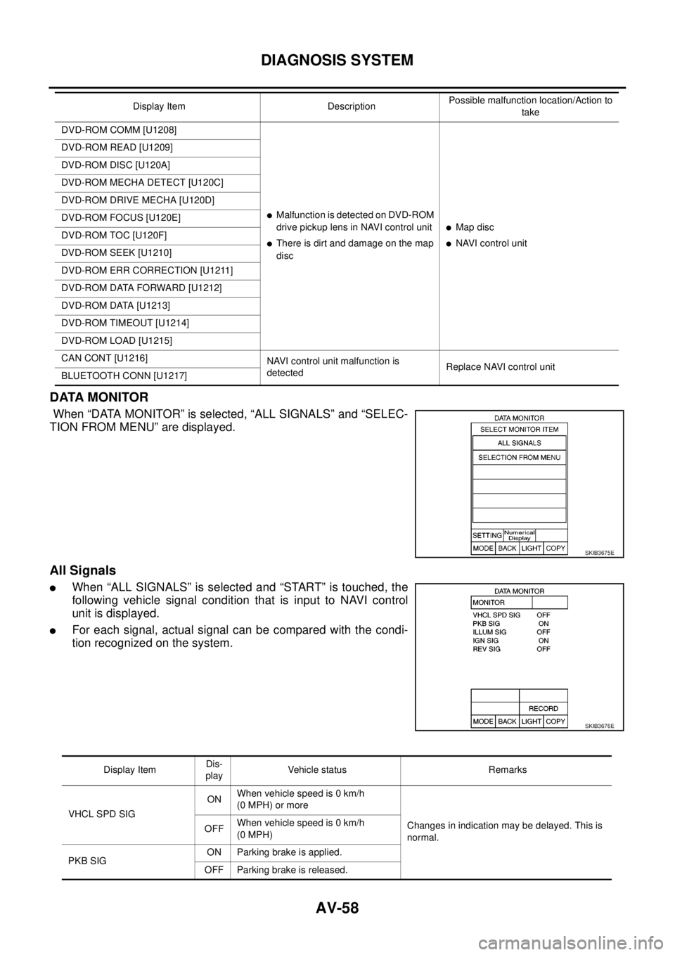
DATA MONITOR
When “DATA MONITOR” is selected, “ALL SIGNALS” and “SELEC-
TION FROM MENU” are displayed.
All Signals
lWhen “ALL SIGNALS” is selected and “START” is touched, the
following vehicle signal condition that is input to NAVI control
unit is displayed.
lFor each signal, actual signal can be compared with the condi-
tion recognized on the system.
DVD-ROM COMM [U1208]
lMalfunctionisdetectedonDVD-ROM
drive pickup lens in NAVI control unit
lThere is dirt and damage on the map
disc
lMap disc
lNAVI control unit DVD-ROM READ [U1209]
DVD-ROM DISC [U120A]
DVD-ROM MECHA DETECT [U120C]
DVD-ROM DRIVE MECHA [U120D]
DVD-ROM FOCUS [U120E]
DVD-ROM TOC [U120F]
DVD-ROM SEEK [U1210]
DVD-ROM ERR CORRECTION [U1211]
DVD-ROM DATA FORWARD [U1212]
DVD-ROM DATA [U1213]
DVD-ROM TIMEOUT [U1214]
DVD-ROM LOAD [U1215]
CAN CONT [U1216]
NAVI control unit malfunction is
detectedReplace NAVI control unit
BLUETOOTH CONN [U1217]Display Item DescriptionPossible malfunction location/Action to
take
SKIB3675E
SKIB3676E
Display ItemDis-
playVehicle status Remarks
VHCL SPD SIGONWhen vehicle speed is 0 km/h
(0 MPH) or more
Changes in indication may be delayed. This is
normal. OFFWhen vehicle speed is 0 km/h
(0 MPH)
PKB SIGON Parking brake is applied.
OFF Parking brake is released.
Page 560 of 3171

AV-72
TROUBLE DIAGNOSIS
–Because calculation of the current location cannot be done when traveling with the ignition OFF, for exam-
ple when traveling by ferry or when being towed, the location before travel is displayed. If the precise loca-
tioncanbedetectedwithGPS,thelocationwillbecorrected.
THE CURRENT POSITION MARK JUMPS.
In the following cases, the current location mark may appear to jump as a result of automatic correction of the
current location.
lWhen map matching has been done
–If current location and the current location mark are different when map matching is done, the current
location mark may seem to jump. At this time, the location may be “corrected” to the incorrect road or to a
location which is not on a road.
lWhen GPS location correction has been done
–If current location and the current location mark are different when location is corrected using GPS mea-
surements, the current location mark may seem to jump. At this time, the location may be “corrected” to a
location which is not on a road.
THE CURRENT LOCATION MARK IS IN A RIVER OR THE SEA.
The navigation system moves the current location mark with no distinction between land and rivers or sea. If
the location mark is somehow out of place, it may appear that the vehicle is driving in a river or the sea.
CURRENT LOCATION MARK ROTATES WITHOUT OPERATION
If the ignition switch is turned ON with the turntable rotating, the rotating condition is recorded as the stop con-
dition. Therefore, the current location mark might rotate when actually stopping.
WHEN DRIVING ON THE SAME ROAD, SOMETIMES THE CURRENT LOCATION MARK IS IN
THE CORRECT PLACE AND SOMETIMES IT IS IN THE INCORRECT PLACE.
The conditions of the GPS antenna (GPS data) and gyroscope (angular speed sensor) change gradually.
Depending on the road traveled and operation of the steering wheel, the location detection results will be dif-
ferent. Therefore, even on a road on which the location has never been incorrect, conditions may cause the
vehicle mark to deviate.
LOCATION CORRECTION BY MAP MATCHING IS SLOW.
lThe map matching function needs to refer to the data of the surrounding area. It is necessary to drive
some distance for the function to work.
lBecause of the way map matching operates, when there are many roads running in similar directions in
the surrounding area a matching determination may be impossible. The location will remain uncorrected
until some special feature is found.
ALTHOUGH THE GPS RECEIVING DISPLAY IS GREEN, THE VEHICLE MARK DOES NOT
RETURN TO THE CORRECT LOCATION.
lGPS accuracy has a malfunction range of about 10 m. In some cases the current location mark may not
be on the correct street, even when GPS location correction is done.
lThe navigation system compares the results of GPS location detection with the results from map-match-
ing location detection. The one that is determined to have higher accuracy is used.
lPosition correction by GPS is not available while the vehicle is stopped.
THE NAME OF THE CURRENT PLACE IS NOT DISPLAYED.
The current place name might not be displayed when there is no name of place information in the map screen.
THE DISPLAY IS DIFFERENT BETWEEN BIRDVIEW®AND (FLAT) MAP DISPLAY.
The following is different at birdview®.
lThe current place name displays names that are primarily in the direction of vehicle travel.
lThe amount of time before the vehicle travel or turn angle is updated on the screen is longer than for the
(flat) map display.
lThe conditions for display of place names, roads, and other data are different for nearby areas and for
more distant areas.
lSome trimming of the character data is done to prevent the display from becoming too complex. In some
cases and in some locations, the display contents may differ.
lThe same place name, street name, etc. may be displayed multiple times.
Page 569 of 3171

BCM (BODY CONTROL MODULE)
BCS-3
C
D
E
F
G
H
I
J
L
MA
B
BCS
BCM (BODY CONTROL MODULE)PFP:284B2
System DescriptionEKS00PA1
lBCM (Body Control Module) controls the operation of various electrical units installed on the vehicle.
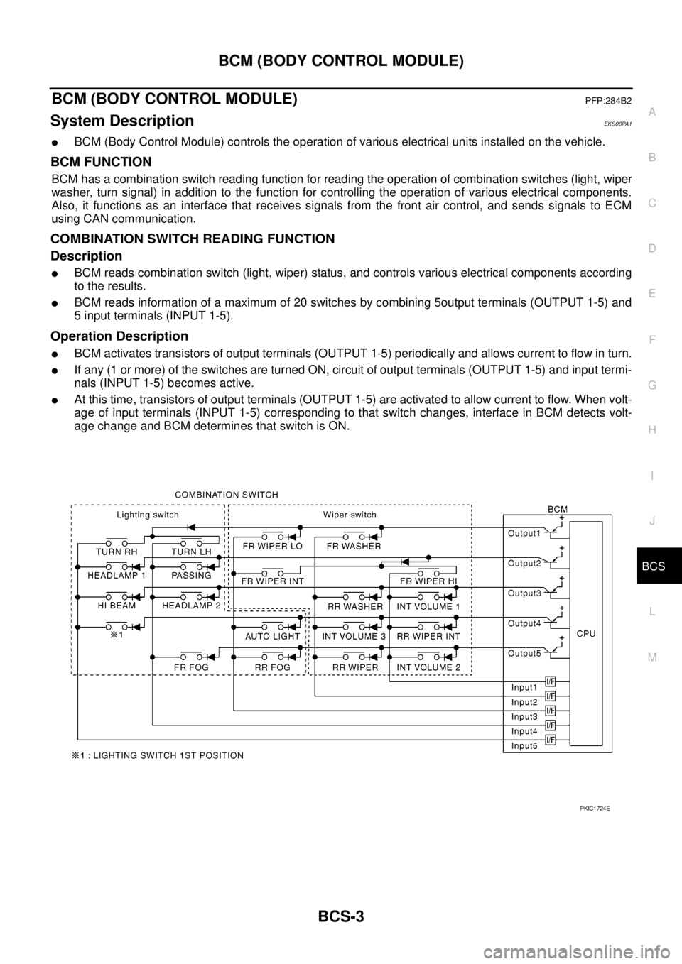
BCM FUNCTION
BCM has a combination switch reading function for reading the operation of combination switches (light, wiper
washer, turn signal) in addition to the function for controlling the operation of various electrical components.
Also, it functions as an interface that receives signals from the front air control, and sends signals to ECM
using CAN communication.
COMBINATION SWITCH READING FUNCTION
Description
lBCM reads combination switch (light, wiper) status, and controls various electrical components according
to the results.
lBCM reads information of a maximum of 20 switches by combining 5output terminals (OUTPUT 1-5) and
5 input terminals (INPUT 1-5).
Operation Description
lBCM activates transistors of output terminals (OUTPUT 1-5) periodically and allows current to flow in turn.
lIf any (1 or more) of the switches are turned ON, circuit of output terminals (OUTPUT 1-5) and input termi-
nals (INPUT 1-5) becomes active.
lAt this time, transistors of output terminals (OUTPUT 1-5) are activated to allow current to flow. When volt-
age of input terminals (INPUT 1-5) corresponding to that switch changes, interface in BCM detects volt-
age change and BCM determines that switch is ON.
PKIC1724E
Page 571 of 3171

BCM (BODY CONTROL MODULE)
BCS-5
C
D
E
F
G
H
I
J
L
MA
B
BCS
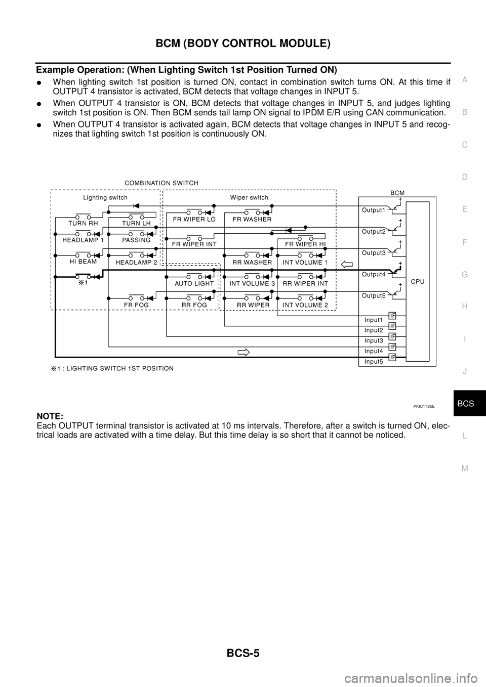
Example Operation: (When Lighting Switch 1st Position Turned ON)
lWhen lighting switch 1st position is turned ON, contact in combination switch turns ON. At this time if
OUTPUT 4 transistor is activated, BCM detects that voltage changes in INPUT 5.
lWhen OUTPUT 4 transistor is ON, BCM detects that voltage changes in INPUT 5, and judges lighting
switch 1st position is ON. Then BCM sends tail lamp ON signal to IPDM E/R using CAN communication.
lWhen OUTPUT 4 transistor is activated again, BCM detects that voltage changes in INPUT 5 and recog-
nizes that lighting switch 1st position is continuously ON.
NOTE:
Each OUTPUT terminal transistor is activated at 10 ms intervals. Therefore, after a switch is turned ON, elec-
trical loads are activated with a time delay. But this time delay is so short that it cannot be noticed.
PKIC1725E
Page 580 of 3171

BCS-14
BCM (BODY CONTROL MODULE)
CONSULT-II Function (BCM)
EKS00PA4
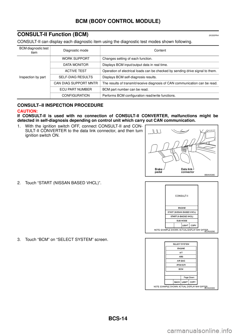
CONSULT-II can display each diagnostic item using the diagnostic test modes shown following.
CONSULT–II INSPECTION PROCEDURE
CAUTION:
If CONSULT-II is used with no connection of CONSULT-II CONVERTER, malfunctions might be
detected in self-diagnosis depending on control unit which carry out CAN communication.
1. With the ignition switch OFF, connect CONSULT-II and CON-
SULT-II CONVERTER to the data link connector, and then turn
ignition switch ON.
2. Touch “START (NISSAN BASED VHCL)”.
3. Touch “BCM” on “SELECT SYSTEM” screen.
BCM diagnostic test
itemDiagnostic mode Content
Inspection by partWORK SUPPORT Changes setting of each function.
DATA MONITOR Displays BCM input/output data in real time.
ACTIVE TEST Operation of electrical loads can be checked by sending drive signal to them.
SELF-DIAG RESULTS Displays BCM self-diagnosis results.
CAN DIAG SUPPORT MNTR The results of transmit/receive diagnosis of CAN communication can be read.
ECU PART NUMBER BCM part number can be read.
CONFIGURATION Performs BCM configuration read/write functions.
BBIA0538E
BCIA0029E
BCIA0030E