2005 NISSAN NAVARA ECO mode
[x] Cancel search: ECO modePage 2241 of 3171
LT-158
INTERIOR ROOM LAMP
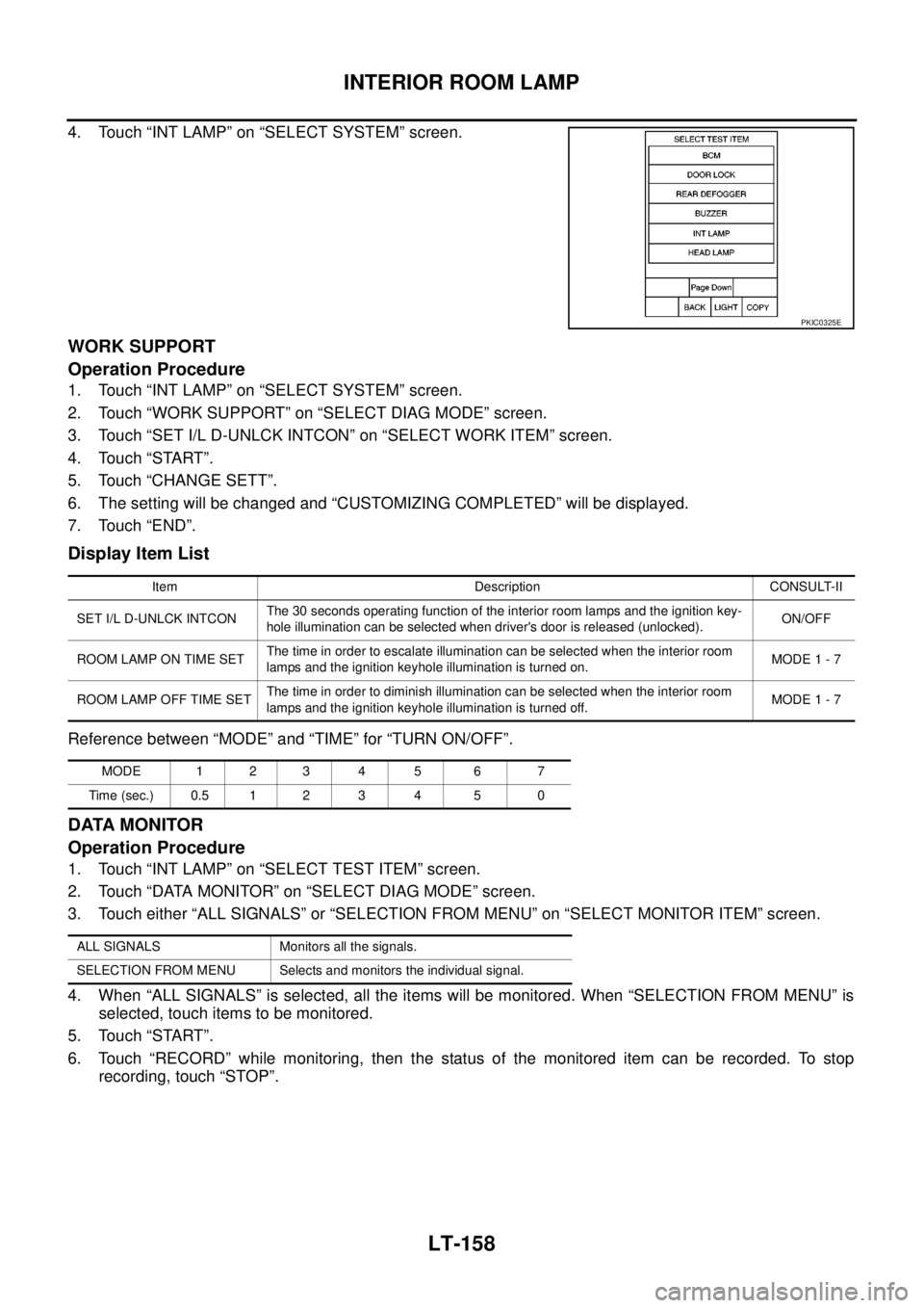
4. Touch “INT LAMP” on “SELECT SYSTEM” screen.
WORK SUPPORT
Operation Procedure
1. Touch “INT LAMP” on “SELECT SYSTEM” screen.
2. Touch “WORK SUPPORT” on “SELECT DIAG MODE” screen.
3. Touch “SET I/L D-UNLCK INTCON” on “SELECT WORK ITEM” screen.
4. Touch “START”.
5. Touch “CHANGE SETT”.
6. The setting will be changed and “CUSTOMIZING COMPLETED” will be displayed.
7. Touch “END”.
Display Item List
Reference between “MODE” and “TIME” for “TURN ON/OFF”.
DATA MONITOR
Operation Procedure
1. Touch “INT LAMP” on “SELECT TEST ITEM” screen.
2. Touch “DATA MONITOR” on “SELECT DIAG MODE” screen.
3. Touch either “ALL SIGNALS” or “SELECTION FROM MENU” on “SELECT MONITOR ITEM” screen.
4. When “ALL SIGNALS” is selected, all the items will be monitored. When “SELECTION FROM MENU” is
selected, touch items to be monitored.
5. Touch “START”.
6. Touch “RECORD” while monitoring, then the status of the monitored item can be recorded. To stop
recording, touch “STOP”.
PKIC0325E
Item Description CONSULT-II
SET I/L D-UNLCK INTCONThe 30 seconds operating function of the interior room lamps and the ignition key-
hole illumination can be selected when driver's door is released (unlocked).ON/OFF
ROOM LAMP ON TIME SETThe time in order to escalate illumination can be selected when the interior room
lamps and the ignition keyhole illumination is turned on.MODE 1 - 7
ROOM LAMP OFF TIME SETThe time in order to diminish illumination can be selected when the interior room
lamps and the ignition keyhole illumination is turned off.MODE 1 - 7
MODE 1 2 3 4 5 6 7
Time (sec.) 0.5 1 2 3 4 5 0
ALL SIGNALS Monitors all the signals.
SELECTION FROM MENU Selects and monitors the individual signal.
Page 2262 of 3171
ENGINE OIL
LU-5
C
D
E
F
G
H
I
J
K
L
MA
LU
ENGINE OILPFP:KLA92
InspectionEBS01E56
ENGINE OIL LEVEL
NOTE:
Before starting engine, put vehicle horizontally and check the engine oil level. If engine is already started, stop
it and allow 10 minutes before checking.
1. Pull out oil level gauge and wipe it clean.
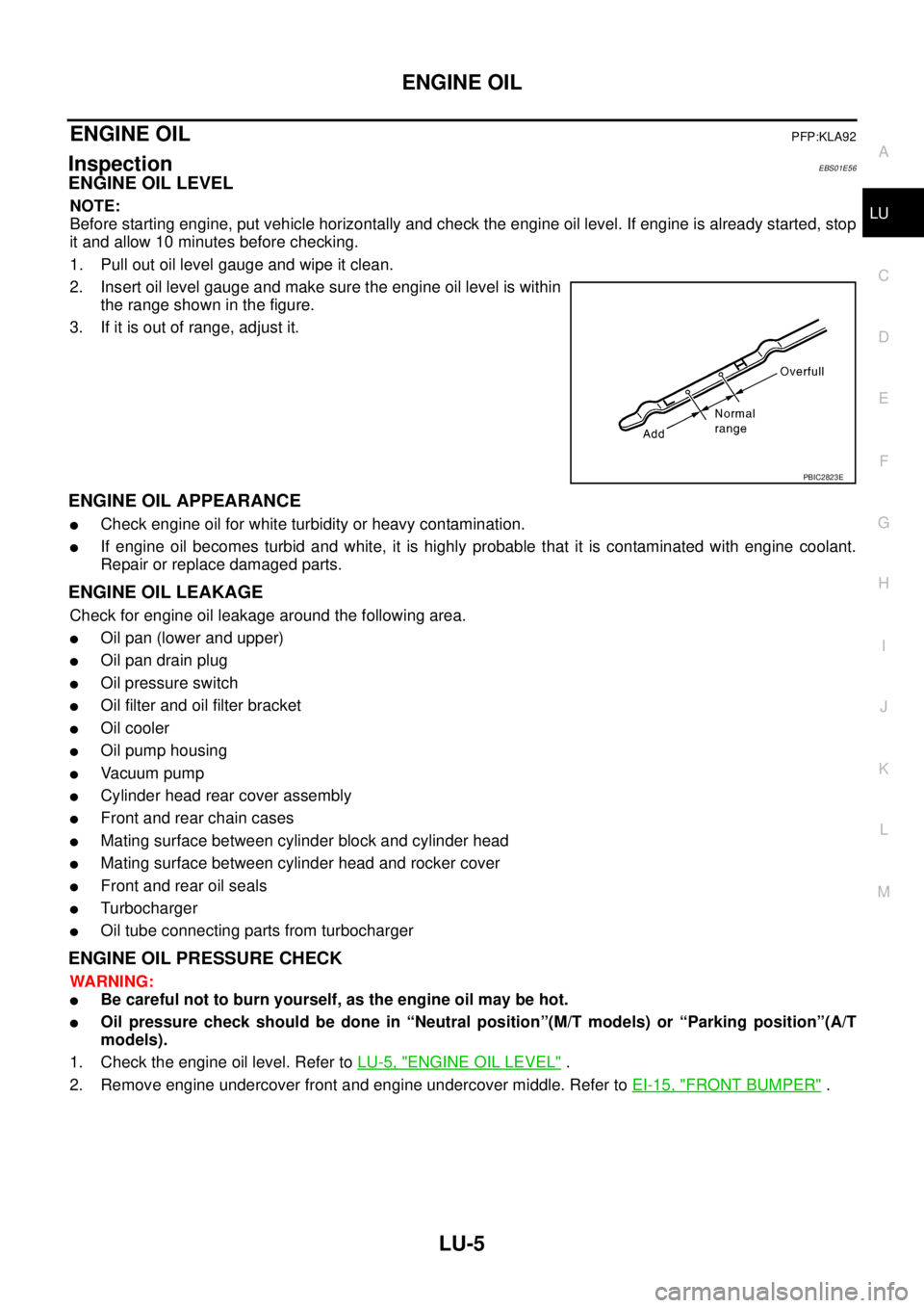
2. Insert oil level gauge and make sure the engine oil level is within
the range shown in the figure.
3. If it is out of range, adjust it.
ENGINE OIL APPEARANCE
lCheck engine oil for white turbidity or heavy contamination.
lIf engine oil becomes turbid and white, it is highly probable that it is contaminated with engine coolant.
Repair or replace damaged parts.
ENGINE OIL LEAKAGE
Check for engine oil leakage around the following area.
lOil pan (lower and upper)
lOil pan drain plug
lOil pressure switch
lOil filter and oil filter bracket
lOil cooler
lOil pump housing
lVa c u u m p u m p
lCylinder head rear cover assembly
lFront and rear chain cases
lMating surface between cylinder block and cylinder head
lMating surface between cylinder head and rocker cover
lFront and rear oil seals
lTurbocharger
lOil tube connecting parts from turbocharger
ENGINE OIL PRESSURE CHECK
WARNING:
lBe careful not to burn yourself, as the engine oil may be hot.
lOil pressure check should be done in “Neutral position”(M/T models) or “Parking position”(A/T
models).
1. Check the engine oil level. Refer toLU-5, "
ENGINE OIL LEVEL".
2. Remove engine undercover front and engine undercover middle. Refer toEI-15, "
FRONT BUMPER".
PBIC2823E
Page 2280 of 3171
DESCRIPTION
MA-5
C
D
E
F
G
H
I
J
K
MA
B
MA
DESCRIPTIONPFP:00000
Pre-Delivery Inspection ItemsELS001K2
Shown below are Pre-delivery Inspection Items required for the new vehicle. It is recommended that
necessary items other than those listed here be added, paying due regard to the conditions in each
country.
Perform applicable items on each model. Consult text of this section for specifications.
Install vehicle protection kit
Fit all accessories ordered (if applicable) (e.g. towbar, audio, navigation, air conditioner, styling kit)
UNDER HOOD — engine off
Check coolant level and cooling system for leaks
Charge battery and check terminals for condition
Check drive belts tension
Check fuel filter for water or dust (diesel only) and fuel system for leaks
Check engine oil level and for oil leaks
Check brake and clutch fluid levels and fluid lines for leaks
Check and top up washer reservoirs
Check power steering fluid level and fluid lines for leaks (if applicable)
Check air conditioning system for gas leaks (if applicable)
ON INSIDE AND OUTSIDE
Install transit fuse if removed for vehicle storage
Check instruments, gauges, lamps, horn and accessories for operation
Check wipers and washers for operation and adjustment
Check interior and door mirrors and sun visors for operation
Set radio code and set clock
Check parking brake adjustment
Check clutch pedal adjustment
Check steering lock operation
Check seat adjusters and seat belts for operation
Check all windows for operation and alignment
Check mouldings, trim and fittings for fit and alignment
Check weatherstrips for fit and adhesion
Check hood, trunk lid, door panels and fuel lid for fit and alignment
Check latches, keys, remote key, door locks and remote trunk lid and fuel lid release for operation
Check wheel nut torques
Check tyre pressure (incl. spare tyre)
Check tool kit and jack for operation
Check automatic transmission/transaxle starter inhibitor (if applicable)
Check sunroof for operation and alignment (if applicable)
UNDER BODY
Check manual transmission/transaxle, differential and transfer box for oil level and oil leaks
Tighten bolts and nuts steering linkage and gear box, axle/suspension parts, propeller and exhaust system
Check brake and clutch lines, and oil/fluid reservoirs for leaks
Remove front suspension spacer blocks (if applicable)
Check body mounting torque (if applicable)
Page 2282 of 3171
GENERAL MAINTENANCE
MA-7
C
D
E
F
G
H
I
J
K
MA
B
MA
GENERAL MAINTENANCEPFP:00000
General MaintenanceELS001HT
General maintenance includes those items which should be checked during the normal day-to-day operation
of the vehicle. They are essential if the vehicle is to continue operating properly. The owners can perform the
checks and inspections themselves or they can have their NISSAN dealers do them for a nominal charge.
OUTSIDE THE VEHICLE
The maintenance items listed here should be performed from time to time, unless otherwise specified.
INSIDE THE VEHICLE
The maintenance items listed here should be checked on a regular basis, such as when performing periodic maintenance, cleaning the
vehicle, etc.
UNDER THE HOOD AND VEHICLE
The maintenance items listed here should be checked periodically e.g. each time you check the engine oil or refuel.Item Reference page
TiresCheck the pressure with a gauge periodically when at a service station, includ-
ing the spare, and adjust to the specified pressure if necessary. Check carefully
for damage, cuts or excessive wear.—
Windshield wiper
bladesCheck for cracks or wear if not functioning correctly. —
Doors and engine
hoodCheck that all doors, the engine hood, the trunk lid and back door operate prop-
erly. Also ensure that all latches lock securely. Lubricate if necessary. Make sure
that the secondary latch keeps the hood from opening when the primary latch is
released.
When driving in areas using road salt or other corrosive materials, check for
lubrication frequently.MA-39
,BL-12
Tire rotationTires should be rotated every 10,000 km (6,000 miles) for 2WD models and
every 5,000 km (3,000 miles) for 4WD models.MA-34
Item Reference page
LampsMake sure that the headlamps, stop lamps, tail lamps, turn signal lamps, and
other lamps are all operating properly and installed securely. Also check
headlamp aim.—
Warning lamps and
chimesMake sure that all warning lamps and buzzers/chimes are operating properly. —
Steering wheelCheck that it has the specified play.
Check for changes in the steering conditions, such as excessive free play, hard
steering or strange noises.
Free play: Less than 35 mm (1.38 in)—
Seat beltsCheck that all parts of the seat belt system (e.g. buckles, anchors, adjusters and
retractors) operate properly and smoothly, and are installed securely. Check the
belt webbing for cuts, fraying, wear or damage.MA-40
Item Reference page
Windshield washer
fluidCheck that there is adequate fluid in the tank. —
Engine coolant levelCheck the coolant level when the engine is cold.MA-19
(YD25DDTi)
Engine oil levelCheck the level after parking the vehicle (on level ground) and turning off the
engine.MA-25
(YD25DDTi)
Brake and clutch fluid
levelsMake sure that the brake and clutch fluid levels are between the “MAX” and
“MIN” lines on the reservoir.MA-28
,MA-35
BatteryCheck the fluid level in each cell. It should be between the “MAX” and “MIN”
lines.—
Page 2289 of 3171

MA-14
RECOMMENDED FLUIDS AND LUBRICANTS
RECOMMENDED FLUIDS AND LUBRICANTS
PFP:00000
Fluids and LubricantsELS001JA
*1: For further details, see “SAE Viscosity Number”.
*2: Never use API CG-4.
*3: Use Genuine NISSAN Anti-freeze Coolant (L250) or equivalent in its quality, in order to avoid possible aluminum corrosion within the
engine cooling system caused by the use of non-genuine engine coolant.
Note that any repairs for the incidents within the engine cooling system while using non-genuine engine coolant may not be
covered by the warranty even if such incidents occurred during the warranty period.
*4: Contact a Nissan dealership for more information regarding suitable fluids, including recommended brand(s) of DEXRON
™III/MER-
CON™ Automatic Transmission Fluid.
*5:Using automatic transmission fluid other than Genuine NISSAN ATF Matic Fluid J will cause deterioration in driveability
and automatic transmission durability, and may damage the automatic transmission, which is not covered by the warranty.
*6: DEXRON™III type ATF can be used.
*7: Never mix different types of fluids (DOT 3 and DOT 4).Capacity (Approximate)
Recommended Fluids/Lubricants
Liter Imp measure
Engine oil
Drain and refillWith oil filter change 7.6 6-5/8 qt
lDiesel engine
API CF-4*1, *2
ACEA B1, B3, B4, B5*1 Without oil filter change 7.1 6-1/4 qt
Dry engine (engine overhaul) 7.9 7 qt
Cooling sys-
tem (with res-
ervoir)LHD models 9.9 8-3/4 qt
lGenuine NISSAN Anti-freeze Coolant (L250) or
equivalent in its quality*3 RHD models 10.2 9 qt
Reservoir tank 0.8 3/4 qt
Manual transmission gear oil2WD 3.99 7 pt
lGenuine NISSAN gear oil or API GL-4, Viscosity
SAE 75W-85 or 75W-90
4WD 4.32 7-5/8 pt
Transfer fluid 2.0 1-3/4 qt
lGenuine NISSAN ATF or equivalent*4
Differential gear oilFront 0.85 1-1/2 pt
lStandard differential gear:
Gear Oil Hypoid LSD (Part No.: KLD31-8090403)
or API GL-5, Viscosity SAE 80W-90*1
lLimited-slip differential (LSD) gear:
Gear Oil Hypoid LSD (Part No. KLD31-8090403)
or equivalent Rear 2.01 3-1/2 pt
Automatic transmission fluid 10.3 9-1/8 qt Genuine NISSAN ATF Matic Fluid J*5
Power steering fluid — — Genuine NISSAN PSF or equivalent*6
Brake and clutch fluid — —
lDOT 3 or DOT 4 (US FMVSS No. 116)*7
Multi-purpose grease — — NLGI No. 2 (Lithium soap base)
Page 2295 of 3171
MA-20
ENGINE MAINTENANCE
REFILLING ENGINE COOLANT
1. Install reservoir tank, and radiator drain plug.
CAUTION:
Be sure to clean radiator drain plug and install with new O-ring.
lIf water drain plug on cylinder block is removed, close and tighten it. Refer toEM-110, "CYLIN-
DER BLOCK".
2. Make sure that each hose clamp has been firmly tightened.
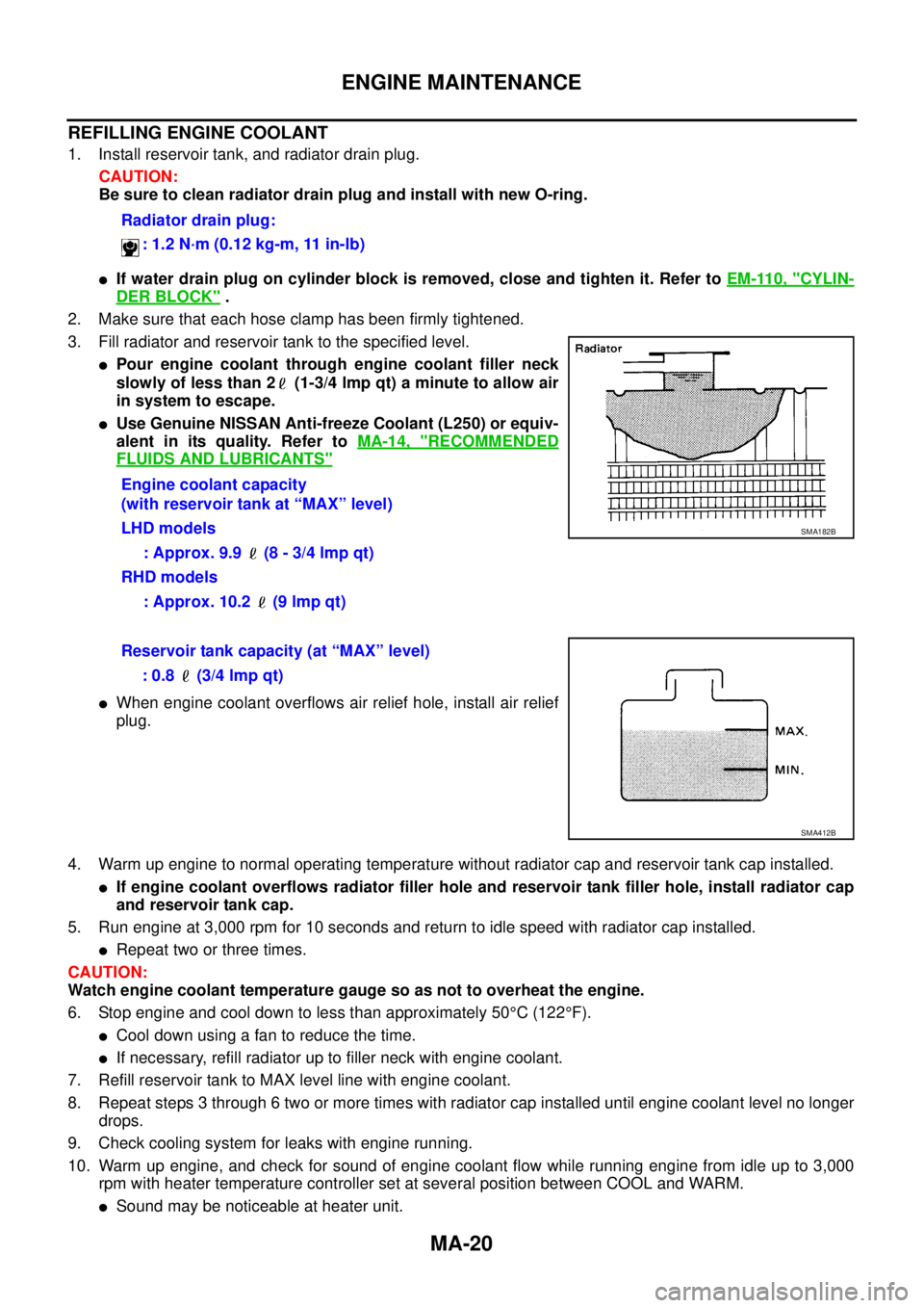
3. Fill radiator and reservoir tank to the specified level.
lPour engine coolant through engine coolant filler neck
slowly of less than 2 (1-3/4 lmp qt) a minute to allow air
in system to escape.
lUse Genuine NISSAN Anti-freeze Coolant (L250) or equiv-
alent in its quality. Refer toMA-14, "
RECOMMENDED
FLUIDS AND LUBRICANTS"
lWhen engine coolant overflows air relief hole, install air relief
plug.
4. Warm up engine to normal operating temperature without radiator cap and reservoir tank cap installed.
lIf engine coolant overflows radiator filler hole and reservoir tank filler hole, install radiator cap
and reservoir tank cap.
5. Run engine at 3,000 rpm for 10 seconds and return to idle speed with radiator cap installed.
lRepeat two or three times.
CAUTION:
Watch engine coolant temperature gauge so as not to overheat the engine.
6. Stop engine and cool down to less than approximately 50°C(122°F).
lCool down using a fan to reduce the time.
lIf necessary, refill radiator up to filler neck with engine coolant.
7. Refill reservoir tank to MAX level line with engine coolant.
8. Repeat steps 3 through 6 two or more times with radiator cap installed until engine coolant level no longer
drops.
9. Check cooling system for leaks with engine running.
10. Warm up engine, and check for sound of engine coolant flow while running engine from idle up to 3,000
rpm with heater temperature controller set at several position between COOL and WARM.
lSound may be noticeable at heater unit.Radiator drain plug:
: 1.2 N·m (0.12 kg-m, 11 in-lb)
Engine coolant capacity
(with reservoir tank at “MAX” level)
LHD models
: Approx. 9.9 (8 - 3/4 lmp qt)
RHD models
: Approx. 10.2 (9 lmp qt)
SMA182B
Reservoir tank capacity (at “MAX” level)
: 0.8 (3/4 lmp qt)
SMA412B
Page 2388 of 3171
MTC-1
MANUAL AIR CONDITIONER
J AIR CONDITIONER
CONTENTS
C
D
E
F
G
H
I
K
L
M
SECTIONMTC
A
B
MTC
MANUAL AIR CONDITIONER
PRECAUTIONS .......................................................... 4
Precautions for Supplemental Restraint System
(SRS)“AIRBAG”and“SEATBELTPRE-TEN-
SIONER” .................................................................. 4
Precautions for Working with HFC-134a (R-134a)..... 4
Contaminated Refrigerant ........................................ 4
General Refrigerant Precautions .............................. 5
Precautions for Refrigerant Connection ................... 5
ABOUT ONE-TOUCH JOINT ................................ 5
FEATURES OF NEW TYPE REFRIGERANT
CONNECTION ...................................................... 7
O-RING AND REFRIGERANT CONNECTION..... 9
Precautions for Servicing Compressor ................... 12
Precautions for Service Equipment ........................ 12
RECOVERY/RECYCLING EQUIPMENT ............ 12
ELECTRONIC LEAK DETECTOR ...................... 12
VACUUM PUMP ................................................. 13
MANIFOLD GAUGE SET .................................... 13
SERVICE HOSES ............................................... 13
SERVICE COUPLERS ........................................ 14
REFRIGERANT WEIGHT SCALE ...................... 14
CALIBRATING ACR4 WEIGHT SCALE .............. 14
CHARGING CYLINDER ...................................... 14
Precautions for Leak Detection Dye ....................... 14
IDENTIFICATION ................................................ 15
IDENTIFICATION LABEL FOR VEHICLE ........... 15
Wiring Diagrams and Trouble Diagnosis ................ 15
PREPARATION ......................................................... 16
Special Service Tools ............................................. 16
HFC-134a (R-134a) Service Tools and Equipment... 16
Commercial Service Tools ...................................... 19
REFRIGERATION SYSTEM ..................................... 20
Refrigerant Cycle ................................................... 20
REFRIGERANT FLOW ....................................... 20
FREEZE PROTECTION ..................................... 20
Refrigerant System Protection ............................... 20
REFRIGERANT PRESSURE SENSOR ............. 20
PRESSURE RELIEF VALVE ............................... 21
Component Layout ................................................. 22
REFRIGERATION SYSTEM ............................... 22LUBRICANT .............................................................. 24
Maintenance of Lubricant Quantity in Compressor... 24
LUBRICANT ........................................................ 24
CHECKING AND ADJUSTING ............................ 24
AIR CONDITIONER CONTROL ............................... 26
Description .............................................................. 26
Operation ................................................................ 26
AIR MIX DOOR CONTROL ................................. 26
BLOWER SPEED CONTROL ............................. 26
INTAKE DOORS CONTROL ............................... 26
MODE DOOR CONTROL ................................... 26
DEFROSTER DOOR CONTROL ........................ 26
MAGNET CLUTCH CONTROL ........................... 27
SELF-DIAGNOSTIC SYSTEM ............................ 27
Description of Control System ................................ 28
Control Operation ................................................... 28
DISPLAY SCREEN .............................................. 29
TEMPERATURE SWITCH (TEMPERATURE
CONTROL) (FRONT) .......................................... 29
RECIRCULATION () SWITCH ............................. 29
REAR WINDOW DEFOGGER SWITCH ............. 29
OFF SWITCH (BLOWER SPEED SET TO 0) ..... 29
A/C SWITCH ....................................................... 29
MODE SWITCH .................................................. 29
Discharge Air Flow ................................................. 30
FRONT ................................................................ 30
System Description ................................................. 31
SWITCHES AND THEIR CONTROL FUNCTION... 31
CAN Communication System Description .............. 32
TROUBLE DIAGNOSIS ............................................ 33
CONSULT-II ............................................................ 33
CONSULT-II BASIC OPERATION ....................... 33
DATA MONITOR ................................................. 34
How to Perform Trouble Diagnosis for Quick and
Accurate Repair ...................................................... 35
WORK FLOW ...................................................... 35
SYMPTOM TABLE .............................................. 35
Component Parts and Harness Connector Location... 36
ENGINE COMPARTMENT .................................. 36
FRONT PASSENGER COMPARTMENT ............ 37
Page 2401 of 3171
MTC-14
PRECAUTIONS
SERVICE COUPLERS
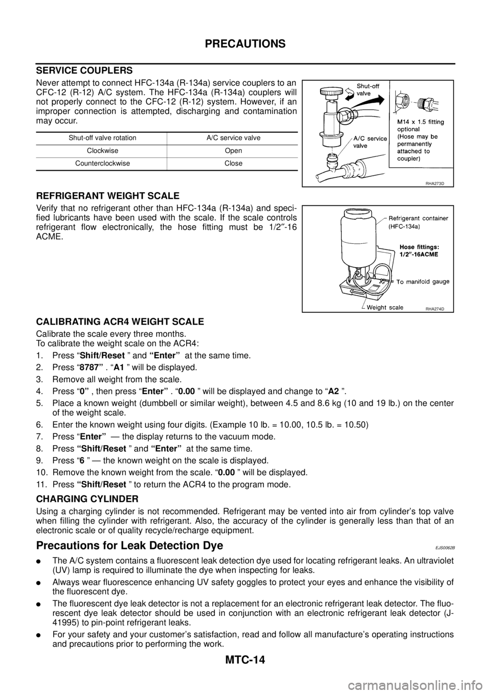
Never attempt to connect HFC-134a (R-134a) service couplers to an
CFC-12 (R-12) A/C system. The HFC-134a (R-134a) couplers will
not properly connect to the CFC-12 (R-12) system. However, if an
improper connection is attempted, discharging and contamination
may occur.
REFRIGERANT WEIGHT SCALE
Verify that no refrigerant other than HFC-134a (R-134a) and speci-
fied lubricants have been used with the scale. If the scale controls
refrigerant flow electronically, the hose fitting must be 1/2²-16
ACME.
CALIBRATING ACR4 WEIGHT SCALE
Calibrate the scale every three months.
To calibrate the weight scale on the ACR4:
1. Press “Shift/Reset”and“Enter”at the same time.
2. Press “8787”.“A1” will be displayed.
3. Remove all weight from the scale.
4. Press “0”, then press “Enter”.“0.00” will be displayed and change to “A2”.
5. Place a known weight (dumbbell or similar weight), between 4.5 and 8.6 kg (10 and 19 lb.) on the center
of the weight scale.
6. Enter the known weight using four digits. (Example 10 lb. = 10.00, 10.5 lb. = 10.50)
7. Press “Enter”— the display returns to the vacuum mode.
8. Press“Shift/Reset”and“Enter”at the same time.
9. Press “6” — the known weight on the scale is displayed.
10. Remove the known weight from the scale. “0.00” will be displayed.
11. Press“Shift/Reset” to return the ACR4 to the program mode.
CHARGING CYLINDER
Using a charging cylinder is not recommended. Refrigerant may be vented into air from cylinder’s top valve
when filling the cylinder with refrigerant. Also, the accuracy of the cylinder is generally less than that of an
electronic scale or of quality recycle/recharge equipment.
Precautions for Leak Detection DyeEJS0062B
lThe A/C system contains a fluorescent leak detection dye used for locating refrigerant leaks. An ultraviolet
(UV) lamp is required to illuminate the dye when inspecting for leaks.
lAlways wear fluorescence enhancing UV safety goggles to protect your eyes and enhance the visibility of
the fluorescent dye.
lThe fluorescent dye leak detector is not a replacement for an electronic refrigerant leak detector. The fluo-
rescent dye leak detector should be used in conjunction with an electronic refrigerant leak detector (J-
41995) to pin-point refrigerant leaks.
lFor your safety and your customer’s satisfaction, read and follow all manufacture’s operating instructions
and precautions prior to performing the work.
Shut-off valve rotation A/C service valve
Clockwise Open
Counterclockwise Close
RHA273D
RHA274D