2005 NISSAN NAVARA ECO mode
[x] Cancel search: ECO modePage 2937 of 3171

SRS-28
TROUBLE DIAGNOSIS
14. Repair the system as outlined by the “Repair order” in “Intermittent Malfunction Diagnostic Code Chart”,
that corresponds to the self-diagnostic result. For replacement procedure of component parts, refer to the
Removal and Installation procedure for the appropriate component.
15. Go toSRS-24, "
DIAGNOSTIC PROCEDURE 3", for final checking.
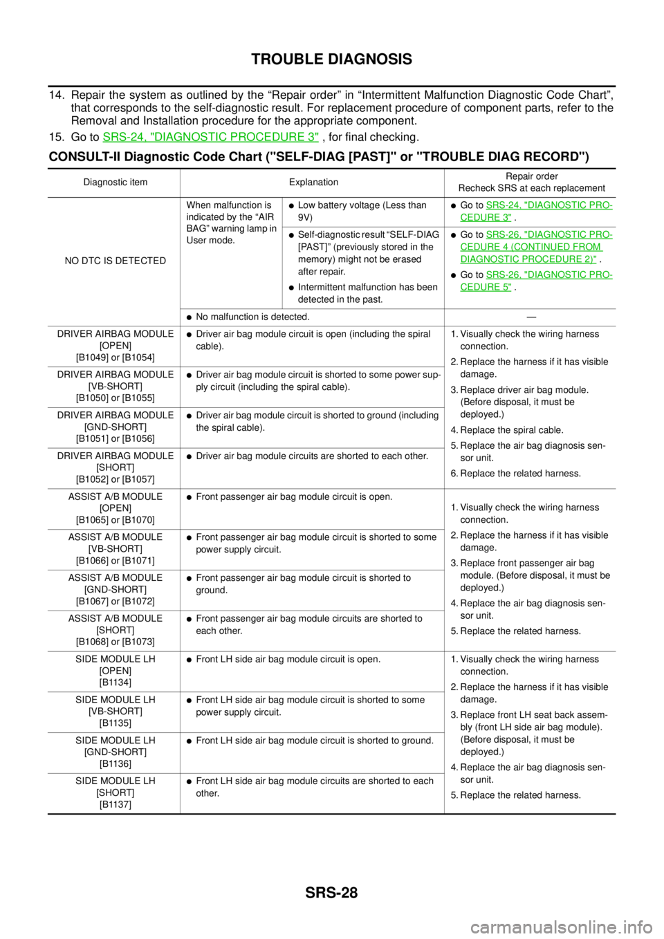
CONSULT-II Diagnostic Code Chart ("SELF-DIAG [PAST]" or "TROUBLE DIAG RECORD")
Diagnostic item ExplanationRepair order
Recheck SRS at each replacement
NO DTC IS DETECTEDWhen malfunction is
indicated by the “AIR
BAG” warning lamp in
User mode.
lLow battery voltage (Less than
9V)lGo toSRS-24, "DIAGNOSTIC PRO-
CEDURE 3".
lSelf-diagnostic result “SELF-DIAG
[PAST]” (previously stored in the
memory) might not be erased
after repair.
lIntermittent malfunction has been
detected in the past.
lGo toSRS-26, "DIAGNOSTIC PRO-
CEDURE 4 (CONTINUED FROM
DIAGNOSTIC PROCEDURE 2)".
lGo toSRS-26, "DIAGNOSTIC PRO-
CEDURE 5".
lNo malfunction is detected. —
DRIVER AIRBAG MODULE
[OPEN]
[B1049] or [B1054]
lDriver air bag module circuit is open (including the spiral
cable).1. Visually check the wiring harness
connection.
2. Replace the harness if it has visible
damage.
3. Replace driver air bag module.
(Before disposal, it must be
deployed.)
4. Replace the spiral cable.
5. Replace the air bag diagnosis sen-
sor unit.
6. Replace the related harness. DRIVER AIRBAG MODULE
[VB-SHORT]
[B1050] or [B1055]
lDriver air bag module circuit is shorted to some power sup-
ply circuit (including the spiral cable).
DRIVER AIRBAG MODULE
[GND-SHORT]
[B1051] or [B1056]
lDriver air bag module circuit is shorted to ground (including
the spiral cable).
DRIVER AIRBAG MODULE
[SHORT]
[B1052] or [B1057]
lDriver air bag module circuits are shorted to each other.
ASSIST A/B MODULE
[OPEN]
[B1065] or [B1070]
lFront passenger air bag module circuit is open.
1. Visually check the wiring harness
connection.
2. Replace the harness if it has visible
damage.
3. Replace front passenger air bag
module. (Before disposal, it must be
deployed.)
4. Replace the air bag diagnosis sen-
sor unit.
5. Replace the related harness. ASSIST A/B MODULE
[VB-SHORT]
[B1066] or [B1071]
lFront passenger air bag module circuit is shorted to some
power supply circuit.
ASSIST A/B MODULE
[GND-SHORT]
[B1067] or [B1072]
lFront passenger air bag module circuit is shorted to
ground.
ASSIST A/B MODULE
[SHORT]
[B1068] or [B1073]
lFront passenger air bag module circuits are shorted to
each other.
SIDE MODULE LH
[OPEN]
[B1134]
lFront LH side air bag module circuit is open. 1. Visually check the wiring harness
connection.
2. Replace the harness if it has visible
damage.
3. Replace front LH seat back assem-
bly (front LH side air bag module).
(Before disposal, it must be
deployed.)
4. Replace the air bag diagnosis sen-
sor unit.
5. Replace the related harness. SIDE MODULE LH
[VB-SHORT]
[B1135]
lFront LH side air bag module circuit is shorted to some
power supply circuit.
SIDE MODULE LH
[GND-SHORT]
[B1136]
lFront LH side air bag module circuit is shorted to ground.
SIDE MODULE LH
[SHORT]
[B1137]
lFront LH side air bag module circuits are shorted to each
other.
Page 2939 of 3171

SRS-30
TROUBLE DIAGNOSIS
Trouble Diagnosis Without CONSULT-II
EHS001XP
DIAGNOSTIC PROCEDURE 6
Inspect SRS Malfunction Using "AIR BAG" Warning Lamp—Diagnosis Mode
NOTE:
SRS will not enter Diagnosis mode if no malfunction is detected in User mode.
1. Turn ignition switch ON.
2. After “AIR BAG” warning lamp lights for 7 seconds, turn ignition switch OFF within 1 second.
3. Wait more than 3 seconds.
4. Repeat steps 1 to 3 two more times (3 times total).
5. Turn ignition switch ON.
SRS is now in Diagnosis mode.
"AIR BAG" warning lamp operates in Diagnosis mode as follows:
CURTAIN MODULE LH
[OPEN]
[B1150]lThe circuit for LH side curtain air bag module is open. 1. Visually check the wiring harness
connection.
2. Replace the harness if it has visible
damage.
3. Replace LH side curtain air bag
module.
(Before disposal, it must be
deployed.)
4. Replace the air bag diagnosis sen-
sor unit.
5. Replace the related harness. CURTAIN MODULE LH
[VB-SHORT]
[B1151]
lThe circuit for LH side curtain air bag module is shorted to
some power supply circuits.
CURTAIN MODULE LH
[GND-SHORT]
[B1152]
lThe circuit for LH side curtain air bag module is shorted to
ground.
CURTAIN MODULE LH
[SHORT]
[B1153]
lThe circuits for the LH side curtain air bag module are
shorted to each other.
CURTAIN MODULE RH
[OPEN]
[B1145]
lThe circuit for RH side curtain air bag module is open. 1. Visually check the wiring harness
connection.
2. Replace the harness if it has visible
damage.
3. Replace RH side curtain air bag
module.
(Before disposal, it must be
deployed.)
4. Replace the air bag diagnosis sen-
sor unit.
5. Replace the related harness. CURTAIN MODULE RH
[VB-SHORT]
[B1146]
lThe circuit for RH side curtain air bag module is shorted to
some power supply circuits.
CURTAIN MODULE RH
[GND-SHORT]
[B1147]
lThe circuit for RH side curtain air bag module is shorted to
ground.
CURTAIN MODULE RH
[SHORT]
[B1148]
lThe circuits for the RH side curtain air bag module are
shorted to each other.
CONTROL UNIT
[B1XXX]
lAir bag diagnosis sensor unit is malfunctioning. 1. Visually check the wiring harness
connection.
2. Replace the harness if it has visible
damage.
3. Replace the air bag diagnosis sen-
sor unit. Diagnostic item ExplanationRepair order
Recheck SRS at each replacement
Page 2972 of 3171

PRECAUTIONS
TF-5
C
E
F
G
H
I
J
K
L
MA
B
TF
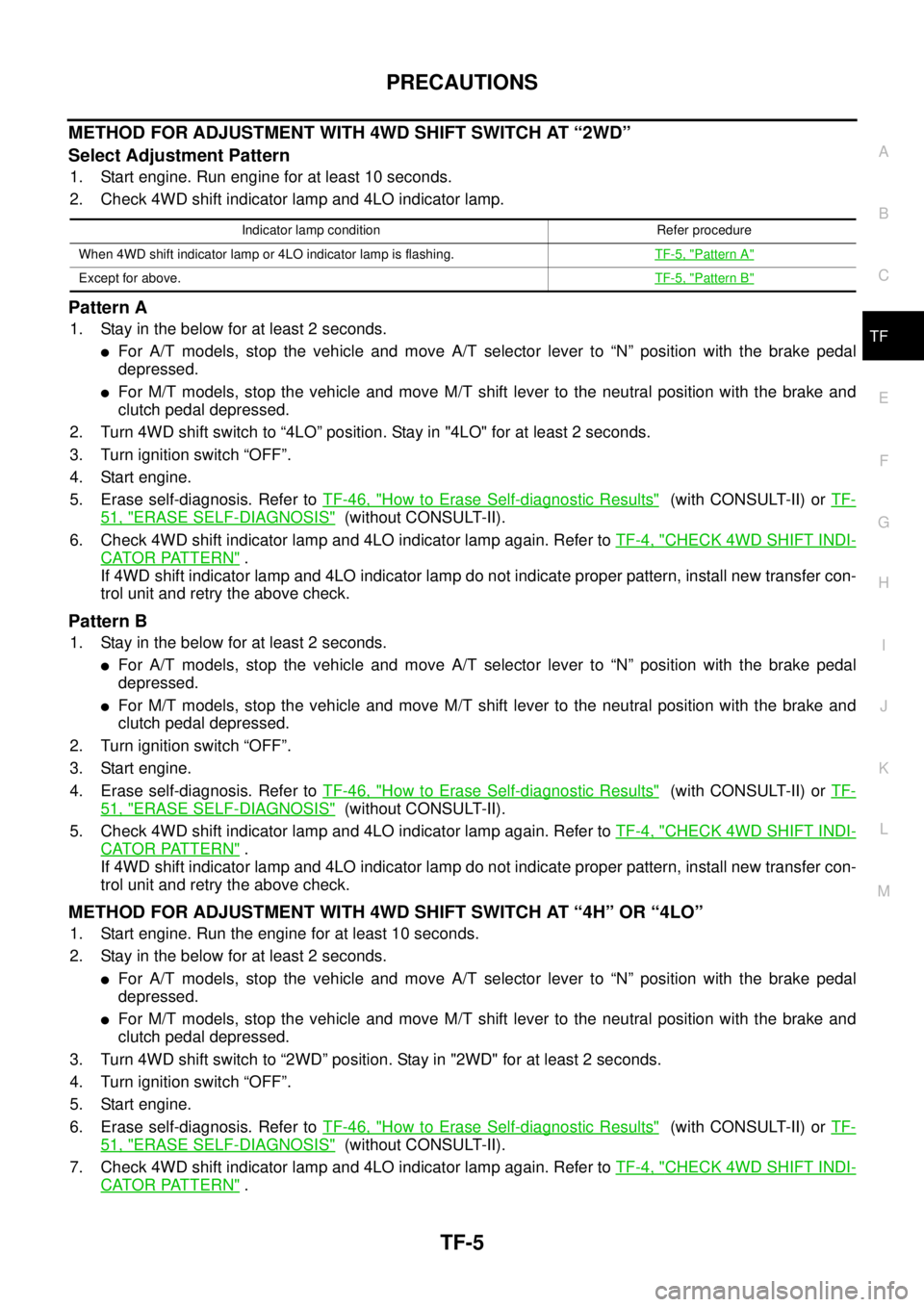
METHODFORADJUSTMENTWITH4WDSHIFTSWITCHAT“2WD”
Select Adjustment Pattern
1. Start engine. Run engine for at least 10 seconds.
2. Check 4WD shift indicator lamp and 4LO indicator lamp.
Pattern A
1. Stay in the below for at least 2 seconds.
lFor A/T models, stop the vehicle and move A/T selector lever to “N” position with the brake pedal
depressed.
lFor M/T models, stop the vehicle and move M/T shift lever to the neutral position with the brake and
clutch pedal depressed.
2. Turn 4WD shift switch to “4LO” position. Stay in "4LO" for at least 2 seconds.
3. Turn ignition switch “OFF”.
4. Start engine.
5. Erase self-diagnosis. Refer toTF-46, "
How to Erase Self-diagnostic Results"(with CONSULT-II) orTF-
51, "ERASE SELF-DIAGNOSIS"(without CONSULT-II).
6. Check 4WD shift indicator lamp and 4LO indicator lamp again. Refer toTF-4, "
CHECK 4WD SHIFT INDI-
CATOR PATTERN".
If 4WD shift indicator lamp and 4LO indicator lamp do not indicate proper pattern, install new transfer con-
trol unit and retry the above check.
Pattern B
1. Stay in the below for at least 2 seconds.
lFor A/T models, stop the vehicle and move A/T selector lever to “N” position with the brake pedal
depressed.
lFor M/T models, stop the vehicle and move M/T shift lever to the neutral position with the brake and
clutch pedal depressed.
2. Turn ignition switch “OFF”.
3. Start engine.
4. Erase self-diagnosis. Refer toTF-46, "
How to Erase Self-diagnostic Results"(with CONSULT-II) orTF-
51, "ERASE SELF-DIAGNOSIS"(without CONSULT-II).
5. Check 4WD shift indicator lamp and 4LO indicator lamp again. Refer toTF-4, "
CHECK 4WD SHIFT INDI-
CATOR PATTERN".
If 4WD shift indicator lamp and 4LO indicator lamp do not indicate proper pattern, install new transfer con-
trol unit and retry the above check.
METHODFORADJUSTMENTWITH4WDSHIFTSWITCHAT“4H”OR“4LO”
1. Start engine. Run the engine for at least 10 seconds.
2. Stay in the below for at least 2 seconds.
lFor A/T models, stop the vehicle and move A/T selector lever to “N” position with the brake pedal
depressed.
lFor M/T models, stop the vehicle and move M/T shift lever to the neutral position with the brake and
clutch pedal depressed.
3. Turn 4WD shift switch to “2WD” position. Stay in "2WD" for at least 2 seconds.
4. Turn ignition switch “OFF”.
5. Start engine.
6. Erase self-diagnosis. Refer toTF-46, "
How to Erase Self-diagnostic Results"(with CONSULT-II) orTF-
51, "ERASE SELF-DIAGNOSIS"(without CONSULT-II).
7. Check 4WD shift indicator lamp and 4LO indicator lamp again. Refer toTF-4, "
CHECK 4WD SHIFT INDI-
CATOR PATTERN".
Indicator lamp condition Refer procedure
When 4WD shift indicator lamp or 4LO indicator lamp is flashing.TF-5, "
Pattern A"
Except for above.TF-5, "Pattern B"
Page 2984 of 3171

4WD SYSTEM
TF-17
C
E
F
G
H
I
J
K
L
MA
B
TF
4WD WARNING LAMP
Turns ON or flashes when there is a malfunction in 4WD system.
Also turns ON when ignition switch is turned ON, for purpose of lamp check. Turns OFF approximately 1 sec-
ond after the engine starts if system is normal.
4WD Warning Lamp Indication
NOTE:
4WD warning lamp is turned on when the following one or more parts are malfunctioning.
lVehicle speed signal
[from ABS actuator and electric unit (control unit)]
lCAN communication line
lAD converter
lEngine speed signal
l4WD shift switch
lWait detection switch
lActuator motor
lTransfer control device
lTransfer shut off relay
lTransfer shift relay
lPNP switch signal
ATP WARNING LAMP (A/T MODELS)
When A/T selector lever is in “P” position, vehicle may move because A/T parking mechanism does not oper-
ate when transfer is under neutral condition. ATP warning lamp is turned on to indicate this condition to the
driver.
Condition 4WD warning lamp
Lamp checkTurns ON when ignition switch is turned ON.
Turns OFF after engine start.
4WD system malfunctionON
(For indicated malfunction items, see the “NOTE”)
During self-diagnosis Flashes at malfunction mode.
Large difference in diameter of front/
rear tiresSlow flashing: 1 time/2 seconds
(Continues to flash until ignition switch is turned OFF)
Other than above (system normal) OFF
Page 2985 of 3171

TF-18
4WD SYSTEM
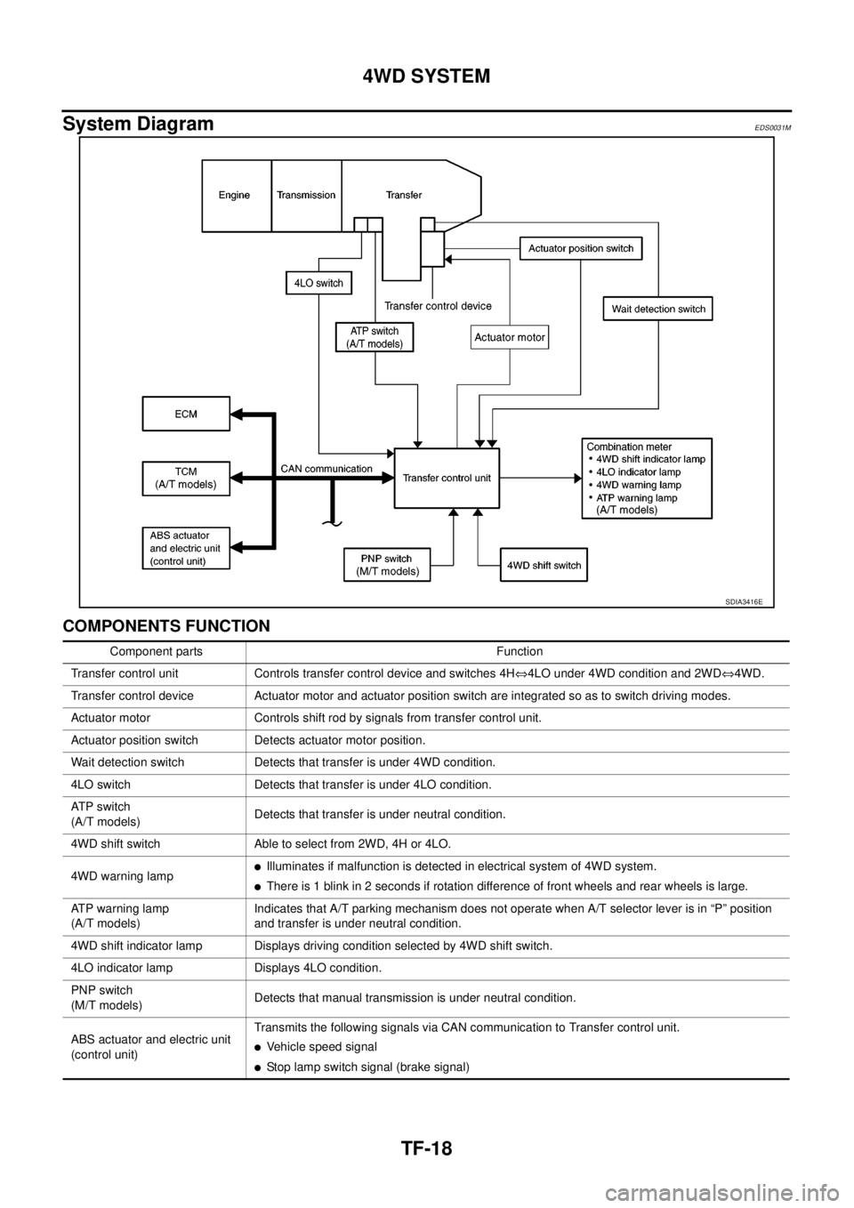
System Diagram
EDS0031M
COMPONENTS FUNCTION
SDIA3416E
Component parts Function
Transfer control unit Controls transfer control device and switches 4HÛ4LO under 4WD condition and 2WDÛ4WD.
Transfer control device Actuator motor and actuator position switch are integrated so as to switch driving modes.
Actuator motor Controls shift rod by signals from transfer control unit.
Actuator position switch Detects actuator motor position.
Wait detection switch Detects that transfer is under 4WD condition.
4LO switch Detects that transfer is under 4LO condition.
AT P s w i t c h
(A/T models)Detects that transfer is under neutral condition.
4WD shift switch Able to select from 2WD, 4H or 4LO.
4WD warning lamp
lIlluminates if malfunction is detected in electrical system of 4WD system.
lThere is 1 blink in 2 seconds if rotation difference of front wheels and rear wheels is large.
ATP warning lamp
(A/T models)Indicates that A/T parking mechanism does not operate when A/T selector lever is in “P” position
and transfer is under neutral condition.
4WD shift indicator lamp Displays driving condition selected by 4WD shift switch.
4LO indicator lamp Displays 4LO condition.
PNP switch
(M/T models)Detects that manual transmission is under neutral condition.
ABS actuator and electric unit
(control unit)Transmits the following signals via CAN communication to Transfer control unit.
lVehicle speed signal
lStop lamp switch signal (brake signal)
Page 3009 of 3171

TF-42
TROUBLE DIAGNOSIS
17 O Wait detection switch
lVehicle stopped
lEngine running
lFor A/T models,
A/T selector
lever “N” position
with brake pedal
depressed.
lFor M/T models,
M/T shift lever
neutral position
with clutch and
brake pedal
depressed.4WD shift switch: 4H and 4LO 0V
4WD shift switch: 2WD Battery voltage
18 B Ground Always 0V
19 RPower supply
(Memory back-up)Ignition switch: ON
Battery voltage
Ignition switch: OFF
23 R ATP switch
lVehicle stopped
lEngine running
lFor A/T models,
A/T selector
lever “N” position
with brake pedal
depressed.
lFor M/T models,
M/T shift lever
neutral position
with clutch and
brake pedal
depressed.4WD shift switch:
4H to 4LO or 4LO to 4H
(While actuator motor is operating.)0V
Except the above Battery voltage
24 Y 4LO switch
lVehicle stopped
lEngine running
lFor A/T models,
A/T selector
lever “N” position
with brake pedal
depressed.
lFor M/T models,
M/T shift lever
neutral position
with clutch and
brake pedal
depressed.4WD shift switch: 4LO 0V
Except the above Battery voltage
25 LG Ignition switch monitorIgnition switch: ON Battery voltage
Ignition switch: OFF 0V
27 L Actuator motor power supplyIgnition switch: ON Battery voltage
Ignition switch: OFF
(5 seconds after ignition switch is turned OFF)0V Te r m i n a lWire
colorItem Condition Data (Approx.)
Page 3010 of 3171

TROUBLE DIAGNOSIS
TF-43
C
E
F
G
H
I
J
K
L
MA
B
TF
28 BR Actuator motor (+)
lVehicle stopped
lEngine running
lFor A/T models,
A/T selector
lever “N” position
with brake pedal
depressed.
lFor M/T models,
M/T shift lever
neutral position
with clutch and
brake pedal
depressed.When 4WD shift switch is operated
(while actuator motor is operating)Battery voltage
®0V
When 4WD shift switch is not operated 0V
31 G Actuator motor (-) Always 0V
32 B Ground Always 0V
33
(For M/T
models)P Park/Neutral position switch Ignition switch: ONM/T shift lever neutral position 0V
Except the above Battery voltage
35 V4WD shift indicator lamp
(Rear indicator)
Engine runningRear indicator of 4WD shift indicator
lamp: ON0V
Rear indicator of 4WD shift indicator
lamp: OFFBattery voltage
36 BR4WD shift indicator lamp
(Front and center indicator)Front and center indicator of 4WD shift
indicator lamp: ON0V
Front and center indicator of 4WD shift
indicator lamp: OFFBattery voltage
37 Y 4LO indicator lamp4LO indicator lamp: ON 0V
4LO indicator lamp: OFF Battery voltage
38 P 4WD warning lamp4WD warning lamp: ON 0V
4WD warning lamp: OFF Battery voltage
39
(For A/T
models)LG ATP warning lamp
lVehicle stopped
lEngine running
lA/T selector
lever “P” position
lBrake pedal
depressed4WD shift switch:
4H to 4LO or 4LO to 4H
(While actuator motor is operating.)Battery voltage
Except the above 0V
40 V Transfer shut off relayIgnition switch: ON 0V
Ignition switch: OFF
(5 seconds after ignition switch is turned OFF)Battery voltage
42 LG Transfer shift high relay
lVehicle stopped
lEngine running
lFor A/T models,
A/T selector
lever “N” position
with brake pedal
depressed.
lFor M/T models,
M/T shift lever
neutral position
with clutch and
brake pedal
depressed.4WD shift switch:
2WD to 4H or 4H to 4LO or 2WD to 4LO0V
Except the above Battery voltage TerminalWire
colorItem Condition Data (Approx.)
Page 3011 of 3171

TF-44
TROUBLE DIAGNOSIS
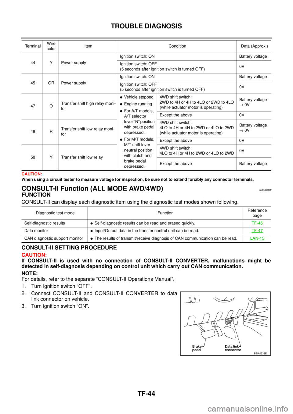
CAUTION:
When using a circuit tester to measure voltage for inspection, be sure not to extend forcibly any connector terminals.
CONSULT-II Function (ALL MODE AWD/4WD)EDS0031W
FUNCTION
CONSULT-II can display each diagnostic item using the diagnostic test modes shown following.
CONSULT-II SETTING PROCEDURE
CAUTION:
If CONSULT-II is used with no connection of CONSULT-II CONVERTER, malfunctions might be
detected in self-diagnosis depending on control unit which carry out CAN communication.
NOTE:
For details, refer to the separate “CONSULT-II Operations Manual”.
1. Turn ignition switch “OFF”.
2. Connect CONSULT-II and CONSULT-II CONVERTER to data
link connector on vehicle.
3. Turn ignition switch “ON”.
44 Y Power supplyIgnition switch: ON Battery voltage
Ignition switch: OFF
(5 seconds after ignition switch is turned OFF)0V
45 GR Power supplyIgnition switch: ON Battery voltage
Ignition switch: OFF
(5 seconds after ignition switch is turned OFF)0V
47 OTransfer shift high relay moni-
tor
lVehicle stopped
lEngine running
lFor A/T models,
A/T selector
lever “N” position
with brake pedal
depressed.
lFor M/T models,
M/T shift lever
neutral position
with clutch and
brake pedal
depressed.4WD shift switch:
2WD to 4H or 4H to 4LO or 2WD to 4LO
(while actuator motor is operating)Battery voltage
®0V
Except the above 0V
48 RTransfer shift low relay moni-
tor4WD shift switch:
4LO to 4H or 4H to 2WD or 4LO to 2WD
(while actuator motor is operating)Battery voltage
®0V
Except the above 0V
50 Y Transfer shift low relay4WD shift switch:
4LO to 4H or 4H to 2WD or 4LO to 2WD0V
Except the above Battery voltage Te r m i n a lWire
colorItem Condition Data (Approx.)
Diagnostic test mode FunctionReference
page
Self-diagnostic results
lSelf-diagnostic results can be read and erased quickly.TF-45
Data monitorlInput/Output data in the transfer control unit can be read.TF-47
CAN diagnostic support monitorlThe results of transmit/receive diagnosis of CAN communication can be read.LAN-15
BBIA0538E