2005 NISSAN NAVARA ECO mode
[x] Cancel search: ECO modePage 3050 of 3171
TROUBLE DIAGNOSIS FOR SYSTEM
TF-83
C
E
F
G
H
I
J
K
L
MA
B
TF
DIAGNOSTIC PROCEDURE
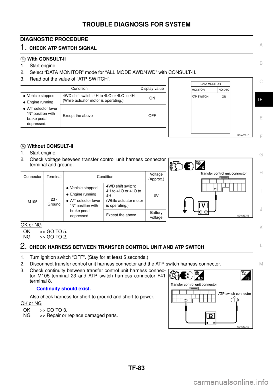
1.CHECK ATP SWITCH SIGNAL
With CONSULT-II
1. Start engine.
2. Select “DATA MONITOR” mode for “ALL MODE AWD/4WD” with CONSULT-II.
3. Read out the value of “ATP SWITCH”.
Without CONSULT-II
1. Start engine.
2. Check voltage between transfer control unit harness connector
terminal and ground.
OK or NG
OK >> GO TO 5.
NG >> GO TO 2.
2.CHECK HARNESS BETWEEN TRANSFER CONTROL UNIT AND ATP SWITCH
1. Turn ignition switch “OFF”. (Stay for at least 5 seconds.)
2. Disconnect transfer control unit harness connector and the ATP switch harness connector.
3. Check continuity between transfer control unit harness connec-
tor M105 terminal 23 and ATP switch harness connector F41
terminal 8.
Also check harness for short to ground and short to power.
OK or NG
OK >> GO TO 3.
NG >> Repair or replace damaged parts.
Condition Display value
lVehicle stopped
lEngine running
lA/T selector lever
“N” position with
brake pedal
depressed.4WD shift switch: 4H to 4LO or 4LO to 4H
(While actuator motor is operating.)ON
Except the above OFF
SDIA2391E
Connector Terminal ConditionVoltage
(Approx.)
M10523 -
Ground
lVehicle stopped
lEngine running
lA/T selector lever
“N” position with
brake pedal
depressed.4WD shift switch:
4H to 4LO or 4LO to
4H
(While actuator motor
is operating.)0V
Except the aboveBattery
voltage
SDIA3375E
Continuity should exist.
SDIA3376E
Page 3091 of 3171
TF-124
TRANSFER ASSEMBLY
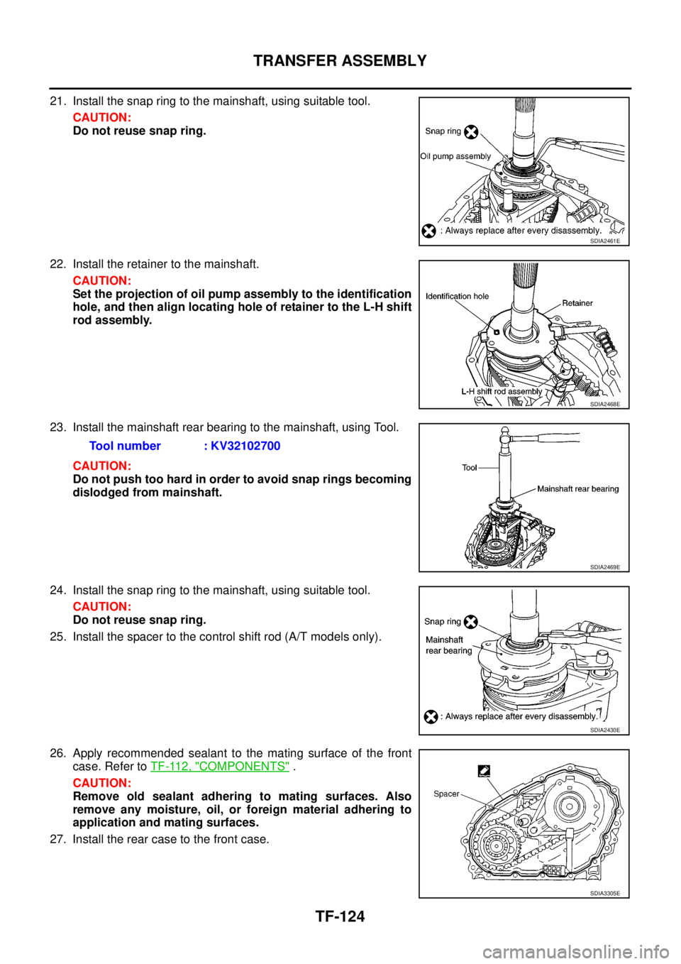
21. Install the snap ring to the mainshaft, using suitable tool.
CAUTION:
Do not reuse snap ring.
22. Install the retainer to the mainshaft.
CAUTION:
Set the projection of oil pump assembly to the identification
hole, and then align locating hole of retainer to the L-H shift
rod assembly.
23. Install the mainshaft rear bearing to the mainshaft, using Tool.
CAUTION:
Do not push too hard in order to avoid snap rings becoming
dislodged from mainshaft.
24. Install the snap ring to the mainshaft, using suitable tool.
CAUTION:
Do not reuse snap ring.
25. Install the spacer to the control shift rod (A/T models only).
26. Apply recommended sealant to the mating surface of the front
case. Refer toTF-112, "
COMPONENTS".
CAUTION:
Remove old sealant adhering to mating surfaces. Also
remove any moisture, oil, or foreign material adhering to
application and mating surfaces.
27. Install the rear case to the front case.
SDIA2461E
SDIA2468E
Tool number : KV32102700
SDIA2469E
SDIA2430E
SDIA3305E
Page 3093 of 3171
TF-126
TRANSFER ASSEMBLY
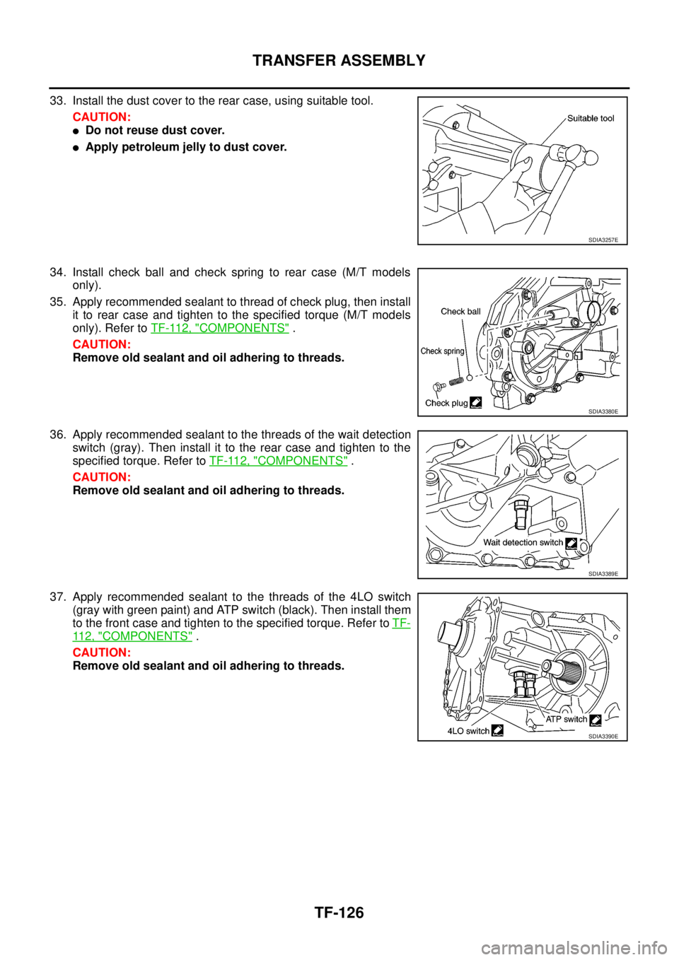
33. Install the dust cover to the rear case, using suitable tool.
CAUTION:
lDo not reuse dust cover.
lApply petroleum jelly to dust cover.
34. Install check ball and check spring to rear case (M/T models
only).
35. Apply recommended sealant to thread of check plug, then install
it to rear case and tighten to the specified torque (M/T models
only). Refer toTF-112, "
COMPONENTS".
CAUTION:
Remove old sealant and oil adhering to threads.
36. Apply recommended sealant to the threads of the wait detection
switch(gray).Theninstallittotherearcaseandtightentothe
specified torque. Refer toTF-112, "
COMPONENTS".
CAUTION:
Remove old sealant and oil adhering to threads.
37. Apply recommended sealant to the threads of the 4LO switch
(gray with green paint) and ATP switch (black). Then install them
to the front case and tighten to the specified torque. Refer toTF-
11 2 , "COMPONENTS".
CAUTION:
Remove old sealant and oil adhering to threads.
SDIA3257E
SDIA3380E
SDIA3389E
SDIA3390E
Page 3130 of 3171
FRONT WIPER AND WASHER SYSTEM
WW-19
C
D
E
F
G
H
I
J
L
MA
B
WW
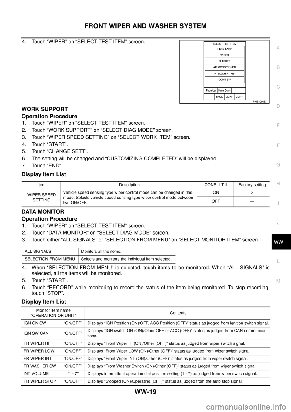
4. Touch “WIPER” on “SELECT TEST ITEM” screen.
WORK SUPPORT
Operation Procedure
1. Touch “WIPER” on “SELECT TEST ITEM” screen.
2. Touch “WORK SUPPORT” on “SELECT DIAG MODE” screen.
3. Touch “WIPER SPEED SETTING” on “SELECT WORK ITEM” screen.
4. Touch “START”.
5. Touch “CHANGE SETT”.
6. The setting will be changed and “CUSTOMIZING COMPLETED” will be displayed.
7. Touch “END”.
Display Item List
DATA MONITOR
Operation Procedure
1. Touch “WIPER” on “SELECT TEST ITEM” screen.
2. Touch “DATA MONITOR” on “SELECT DIAG MODE” screen.
3. Touch either “ALL SIGNALS” or “SELECTION FROM MENU” on “SELECT MONITOR ITEM” screen.
4. When “SELECTION FROM MENU” is selected, touch items to be monitored. When “ALL SIGNALS” is
selected, all the items will be monitored.
5. Touch “START”.
6. Touch “RECORD” while monitoring to record the status of the item being monitored. To stop recording,
touch “STOP”.
Display Item List
PKIB6096E
Item Description CONSULT-II Factory setting
WIPER SPEED
SETTINGVehicle speed sensing type wiper control mode can be changed in this
mode. Selects vehicle speed sensing type wiper control mode between
two ON/OFF.ON´
OFF —
ALL SIGNALS Monitors all the items.
SELECTION FROM MENU Selects and monitors the individual item selected.
Monitor item name
“OPERATION OR UNIT”Contents
IGN ON SW “ON/OFF” Displays “IGN Position (ON)/OFF, ACC Position (OFF)” status as judged from ignition switch signal.
IGN SW CAN “ON/OFF”Displays “IGN switch ON (ON)/Other OFF or ACC (OFF)” status as judged from CAN communica-
tions.
FR WIPER HI “ON/OFF” Displays “Front Wiper HI (ON)/Other (OFF)” status as judged from wiper switch signal.
FR WIPER LOW “ON/OFF” Displays “Front Wiper LOW (ON)/Other (OFF)” status as judged from wiper switch signal.
FR WIPER INT “ON/OFF” Displays “Front Wiper INT (ON)/Other (OFF)” status as judged from wiper switch signal.
FR WASHER SW “ON/OFF” Displays “Front Washer Switch (ON)/Other (OFF)” status as judged from wiper switch signal.
INT VOLUME “1 - 7” Displays intermittent operation dial position setting (1 - 7) as judged from wiper switch signal.
FR WIPER STOP “ON/OFF” Displays “Stopped (ON)/Operating (OFF)” status as judged from the auto stop signal.
Page 3133 of 3171

WW-22
FRONT WIPER AND WASHER SYSTEM
4. Select the desired part to be diagnosed on “SELECT DIAG
MODE” screen.
DATA MONITOR
Operation Procedure
1. Touch "WIPER" on “SELECT TEST ITEM” screen.
2. Touch “DATA MONITOR” on “SELECT DIAG MODE” screen.
3. Touch “ALL SIGNALS”, “MAIN SIGNALS” or “SELECTION FROM MENU” on “SELECT MONITOR ITEM”
screen.
4. When “ALL SIGNALS” is selected, all the items will be monitored. When selecting “MAIN SIGNALS”, pre-
determined items are monitored. When “SELECTION FROM MENU” is selected, touch items to be moni-
tored.
5. Touch “START”.
6. Touch “RECORD” while monitoring to record the status of the item being monitored. To stop recording,
touch “STOP”.
All Items, Main Items, Selection Item Menu
NOTE:
Perform monitoring of IPDM E/R data with the ignition switch ON. When the ignition switch is at ACC, the dis-
play may not be correct.
ACTIVE TEST
Operation Procedure
1. Touch “WIPER” on “SELECT TEST ITEM” screen.
2. Touch “ACTIVE TEST” on “SELECT DIAG MODE” screen.
3. Touch item(s) to be tested and check operation of the selected item(s).
4. During the operation check, touching “BACK” deactivates the operation.
Display Item List
BCIA0031E
ALL SIGNALS Monitors all the items.
MAIN SIGNALS Monitors predetermined items.
SELECTION FROM MENU Selects and monitors the individual item selected.
Item nameCONSULT-II
screen displayDisplay or unitMonitor item selection
Description
ALL
SIGNALSMAIN
SIGNALSSELECTION
FROM
MENU
FR wiper request FR WIP REQ STOP/1LO/LO/HI x x x Signal status input from BCM.
Wiper auto stop WIP AUTO STOP ACT P/STOP P x x x Output status of IPDM E/R.
Wiper protection WIP PROT OFF/LS/HS/BLOCK x x x Control status of IPDM E/R.
Te s t i t e mCONSULT-II
screen displayDescription
Front wiper (HI, LO) output FRONT WIPER With a certain operation (OFF, HI, LO) front wiper relays can be operated.
Page 3139 of 3171
WW-28
FRONT WIPER AND WASHER SYSTEM
Front Wiper Does Not Return to Stop Position (After Front Wiper for 10 Sec-
onds, They Stop for 20 seconds, and After Repeating the Operations Five
Times, They Become Inoperative)
EKS00P57
CAUTION:
lWhen auto stop signal has not varied for 10 seconds or longer while IPDM E/R is operating front
wipers, IPDM E/R considers front wipers are locked, and stops wiper output. That causes this
symptom.
lThis status can be checked by “DATA MONITOR” of “IPDM E/R” on which “WIPER PROTECTION”
ITEMS SHOWS “BLOCK”.
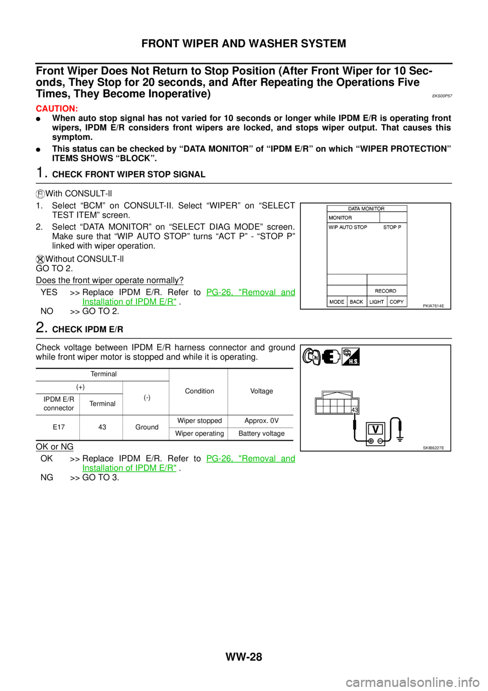
1.CHECK FRONT WIPER STOP SIGNAL
With CONSULT-ll
1. Select “BCM” on CONSULT-II. Select “WIPER” on “SELECT
TEST ITEM” screen.
2. Select “DATA MONITOR” on “SELECT DIAG MODE” screen.
Make sure that “WIP AUTO STOP” turns “ACT P” - “STOP P”
linked with wiper operation.
Without CONSULT-ll
GO TO 2.
Does the front wiper operate normally?
YES >> Replace IPDM E/R. Refer toPG-26, "Removal and
Installation of IPDM E/R".
NO >> GO TO 2.
2.CHECK IPDM E/R
Check voltage between IPDM E/R harness connector and ground
while front wiper motor is stopped and while it is operating.
OK or NG
OK >> Replace IPDM E/R. Refer toPG-26, "Removal and
Installation of IPDM E/R".
NG >> GO TO 3.
PKIA7614E
Terminal
Condition Voltage (+)
(-)
IPDM E/R
connectorTerminal
E17 43 GroundWiper stopped Approx. 0V
Wiper operating Battery voltage
SKIB6227E
Page 3157 of 3171
WW-46
HEADLAMP WASHER
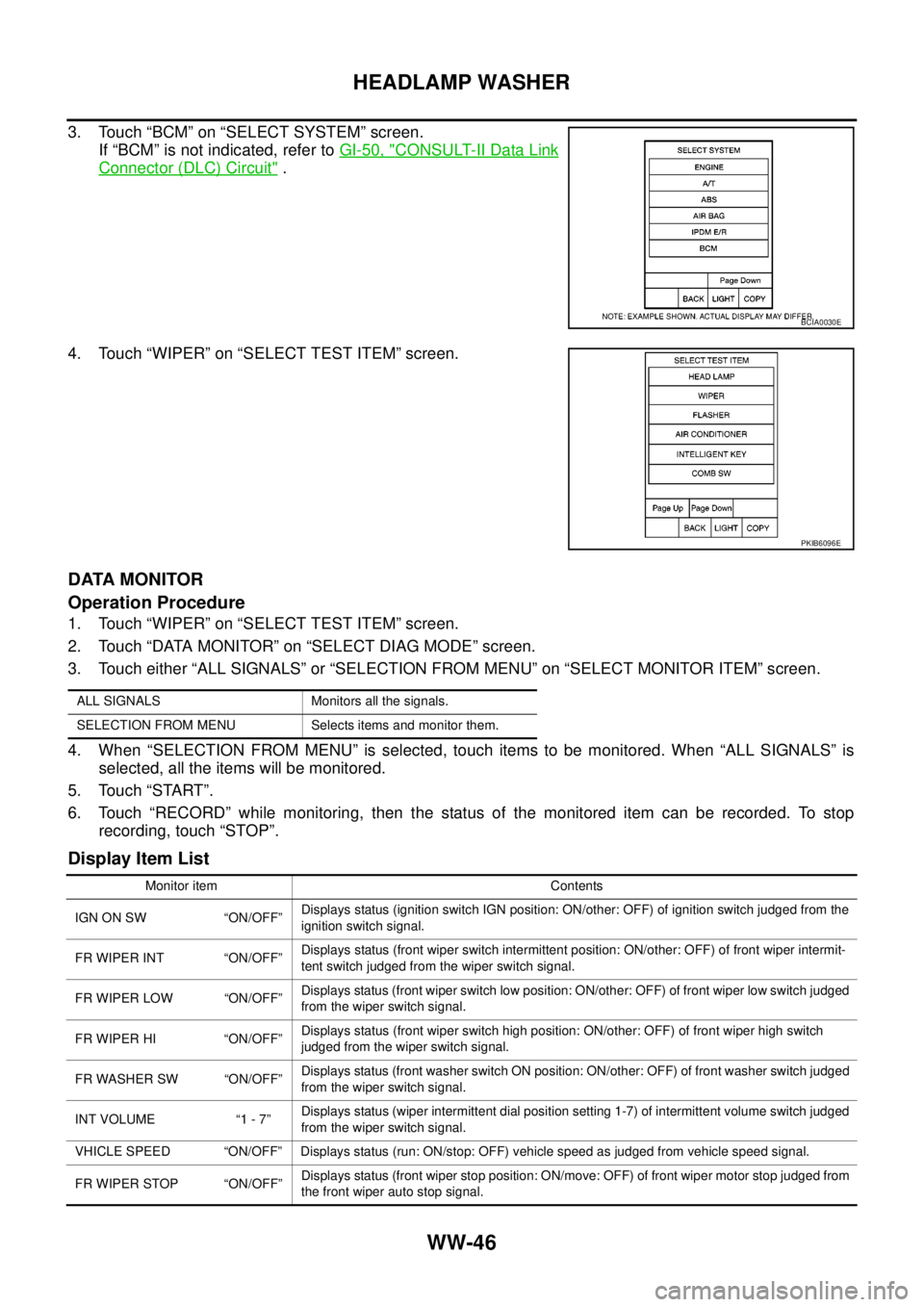
3. Touch “BCM” on “SELECT SYSTEM” screen.
If “BCM” is not indicated, refer toGI-50, "
CONSULT-II Data Link
Connector (DLC) Circuit".
4. Touch “WIPER” on “SELECT TEST ITEM” screen.
DATA MONITOR
Operation Procedure
1. Touch “WIPER” on “SELECT TEST ITEM” screen.
2. Touch “DATA MONITOR” on “SELECT DIAG MODE” screen.
3. Touch either “ALL SIGNALS” or “SELECTION FROM MENU” on “SELECT MONITOR ITEM” screen.
4. When “SELECTION FROM MENU” is selected, touch items to be monitored. When “ALL SIGNALS” is
selected, all the items will be monitored.
5. Touch “START”.
6. Touch “RECORD” while monitoring, then the status of the monitored item can be recorded. To stop
recording, touch “STOP”.
Display Item List
BCIA0030E
PKIB6096E
ALL SIGNALS Monitors all the signals.
SELECTION FROM MENU Selects items and monitor them.
Monitor item Contents
IGN ON SW “ON/OFF”Displays status (ignition switch IGN position: ON/other: OFF) of ignition switch judged from the
ignition switch signal.
FR WIPER INT “ON/OFF”Displays status (front wiper switch intermittent position: ON/other: OFF) of front wiper intermit-
tent switch judged from the wiper switch signal.
FR WIPER LOW “ON/OFF”Displays status (front wiper switch low position: ON/other: OFF) of front wiper low switch judged
from the wiper switch signal.
FR WIPER HI “ON/OFF”Displays status (front wiper switch high position: ON/other: OFF) of front wiper high switch
judged from the wiper switch signal.
FR WASHER SW “ON/OFF”Displays status (front washer switch ON position: ON/other: OFF) of front washer switch judged
from the wiper switch signal.
INT VOLUME “1 - 7”Displays status (wiper intermittent dial position setting 1-7) of intermittent volume switch judged
from the wiper switch signal.
VHICLE SPEED “ON/OFF” Displays status (run: ON/stop: OFF) vehicle speed as judged from vehicle speed signal.
FR WIPER STOP “ON/OFF”Displays status (front wiper stop position: ON/move: OFF) of front wiper motor stop judged from
the front wiper auto stop signal.
Page 3158 of 3171

HEADLAMP WASHER
WW-47
C
D
E
F
G
H
I
J
L
MA
B
WW
ACTIVE TEST
Operation Procedure
1. Touch “WIPER” on “SELECT TEST ITEM” screen.
2. Touch “ACTIVE TEST” on “SELECT DIAG MODE” screen.
3. Touch item to be tested and check operation of the selected item.
4. During the operation check, touching “OFF” deactivates the operation.
Display Item List
RR WIPER INT “ON/OFF”Displays status (rear wiper switch intermittent position: ON/other: OFF) of rear wiper intermit-
tent switch judged from the wiper switch signal.
RR WIPER ON “ON/OFF”Displays status (rear wiper switch ON position: ON/other: OFF) of rear wiper switch judged from
the wiper switch signal.
RR WASHER SW “ON/OFF”Displays status (rear washer switch ON position: ON/other: OFF) of rear washer switch judged
from the wiper switch signal.
RR WIPER STOP “ON/OFF”Displays status (rear wiper move: ON/stop position: OFF) of rear wiper motor stop judged from
the rear wiper auto stop signal.
HL WASHER SW “ON/OFF”Displays status (headlamp washer switch ON position: ON/other: OFF) of headlamp washer
switch judged from headlamp washer switch signal.
HEAD LAMP SW 1 “ON/OFF”Displays status (lighting switch 2ND position: ON/other: OFF) of headlamp 1 switch judged from
thelightingswitchsignal.
HEAD LAMP SW 2 “ON/OFF”Displays status (lighting switch 2ND position: ON/other: OFF) of headlamp 2 switch judged from
thelightingswitchsignal. Monitor item Contents
Test item Display on CONSULT-II screen Description
Front wiper HI output FR WIPER (HI) Front wiper HI can be operated by any ON-OFF operation.
Front wiper LOW output FR WIPER (LOW) Front wiper LOW can be operated by any ON-OFF operation.
Front wiper INT output FR WIPER (INT) Front wiper INT can be operated by any ON-OFF operation.
Rear wiper output RR WIPER Rear wiper can be operated by any ON (1.5 second)-OFF operation.
Headlamp washer output HEAD LAMP WASHER Headlamp washer can be operated by any ON-OFF operation.