2005 NISSAN NAVARA ECO mode
[x] Cancel search: ECO modePage 2421 of 3171
MTC-34
TROUBLE DIAGNOSIS
DATA MONITOR
Operation Procedure
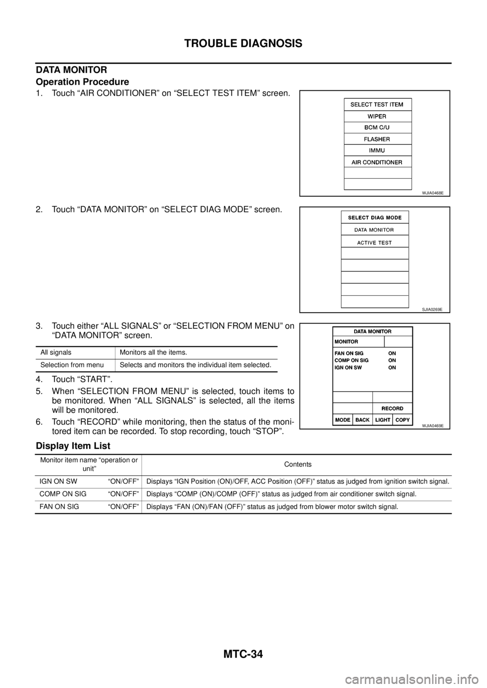
1. Touch “AIR CONDITIONER” on “SELECT TEST ITEM” screen.
2. Touch “DATA MONITOR” on “SELECT DIAG MODE” screen.
3. Touch either “ALL SIGNALS” or “SELECTION FROM MENU” on
“DATA MONITOR” screen.
4. Touch “START”.
5. When “SELECTION FROM MENU” is selected, touch items to
be monitored. When “ALL SIGNALS” is selected, all the items
will be monitored.
6. Touch “RECORD” while monitoring, then the status of the moni-
tored item can be recorded. To stop recording, touch “STOP”.
Display Item List
WJIA0468E
SJIA0269E
All signals Monitors all the items.
Selection from menu Selects and monitors the individual item selected.
WJIA0469E
Monitor item name “operation or
unit”Contents
IGN ON SW “ON/OFF” Displays “IGN Position (ON)/OFF, ACC Position (OFF)” status as judged from ignition switch signal.
COMP ON SIG “ON/OFF” Displays “COMP (ON)/COMP (OFF)” status as judged from air conditioner switch signal.
FAN ON SIG “ON/OFF” Displays “FAN (ON)/FAN (OFF)” status as judged from blower motor switch signal.
Page 2449 of 3171
MTC-62
TROUBLE DIAGNOSIS
7.CHECK PBR FEEDBACK SIGNAL
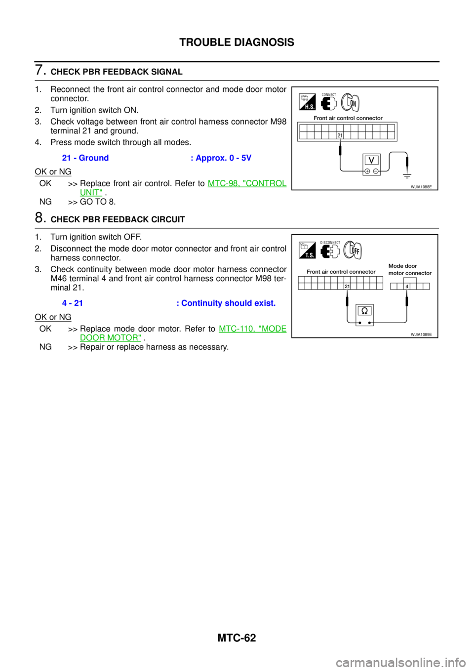
1. Reconnect the front air control connector and mode door motor
connector.
2. Turn ignition switch ON.
3. Check voltage between front air control harness connector M98
terminal 21 and ground.
4. Press mode switch through all modes.
OK or NG
OK >> Replace front air control. Refer toMTC-98, "CONTROL
UNIT".
NG >> GO TO 8.
8.CHECK PBR FEEDBACK CIRCUIT
1. Turn ignition switch OFF.
2. Disconnect the mode door motor connector and front air control
harness connector.
3. Check continuity between mode door motor harness connector
M46 terminal 4 and front air control harness connector M98 ter-
minal 21.
OK or NG
OK >> Replace mode door motor. Refer toMTC-110, "MODE
DOOR MOTOR".
NG >> Repair or replace harness as necessary.21 - Ground : Approx. 0 - 5V
WJIA1088E
4 - 21 : Continuity should exist.
WJIA1089E
Page 2488 of 3171
AIR CONDITIONER FILTER
MTC-101
C
D
E
F
G
H
I
K
L
MA
B
MTC
AIR CONDITIONER FILTERPFP:27277
Removal and InstallationEJS005GW
FUNCTION
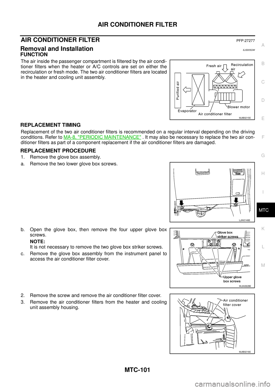
The air inside the passenger compartment is filtered by the air condi-
tioner filters when the heater or A/C controls are set on either the
recirculation or fresh mode. The two air conditioner filters are located
in the heater and cooling unit assembly.
REPLACEMENT TIMING
Replacement of the two air conditioner filters is recommended on a regular interval depending on the driving
conditions. Refer toMA-8, "
PERIODIC MAINTENANCE". It may also be necessary to replace the two air con-
ditioner filters as part of a component replacement if the air conditioner filters are damaged.
REPLACEMENT PROCEDURE
1. Remove the glove box assembly.
a. Remove the two lower glove box screws.
b. Open the glove box, then remove the four upper glove box
screws.
NOTE:
It is not necessary to remove the two glove box striker screws.
c. Remove the glove box assembly from the instrument panel to
access the air conditioner filter cover.
2. Remove the screw and remove the air conditioner filter cover.
3. Remove the air conditioner filters from the heater and cooling
unit assembly housing.
MJIB0215E
LJIA0146E
WJIA0628E
MJIB0216E
Page 2520 of 3171
REFRIGERANT LINES
MTC-133
C
D
E
F
G
H
I
K
L
MA
B
MTC
CHECKING PROCEDURE
To prevent inaccurate or false readings, make sure there is no refrigerant vapor, shop chemicals, or cigarette
smoke in the vicinity of the vehicle. Perform the leak test in calm area (low air/wind movement) so that the
leaking refrigerant is not dispersed.
1. Turn engine OFF.
2. Connect a suitable A/C manifold gauge set (SST) to the A/C service valves.
3. Check if the A/C refrigerant pressure is at least 345 kPa (3.45 bar, 3.52 kg/cm
2, 50 psi) above 16°C. If
less than specification, recover/evacuate and recharge the system with the specified amount of refriger-
ant.
NOTE:
At temperatures below 16°C, leaks may not be detected since the system may not reach 345 kPa (3.45
bar, 3.52 kg/cm
2,50psi).
4. Perform the leak test from the high-pressure side (compressor discharge a to evaporator inlet g) to the
low-pressure side (evaporator drain hose h to shaft seal l). Refer toMTC-120, "
Components". Perform a
leak check for the following areas carefully. Clean the component to be checked and move the leak
detected probe completely around the connection/component.
Compressor
Check the fitting of high- and low-pressure flexible hoses, relief valve and shaft seal.
Liquid tank
Check the refrigerant pressure sensor.
Service valves
Check all around the service valves. Ensure service valve caps are secured on the service valves (to pre-
vent leaks).
NOTE:
After removing A/C manifold gauge set from service valves, wipe any residue from valves to prevent any
false readings by leak detector.
Cooling unit (Evaporator)
With engine OFF, turn blower fan on “High” for at least 15 seconds to dissipate any refrigerant trace in the
cooling unit. Wait a minimum of 10 minutes accumulation time (refer to the manufacturer’s recommended
procedure for actual wait time) before inserting the leak detector probe into the drain hose.
Keep the probe inserted for at least 10 seconds. Use caution not to contaminate the probe tip with water
or dirt that may be in the drain hose.
5. If a leak detector detects a leak, verify at least once by blowing compressed air into area of suspected
leak, then repeat check as outlined above.
6. Do not stop when one leak is found. Continue to check for additional leaks at all system components.
If no leaks are found, perform steps 7 - 10.
7. Start engine.
8. Set the heater A/C control as follows;
a. A/C switch: ON
b. MODE control dial: VENT (Ventilation)
c. Intake door position: Recirculation
d. Max. cold temperature
e. Fan speed: High
9. Run engine at 1,500 rpm for at least 2 minutes.
10. Turn engine off and perform leak check again following steps 4 through 6 above.
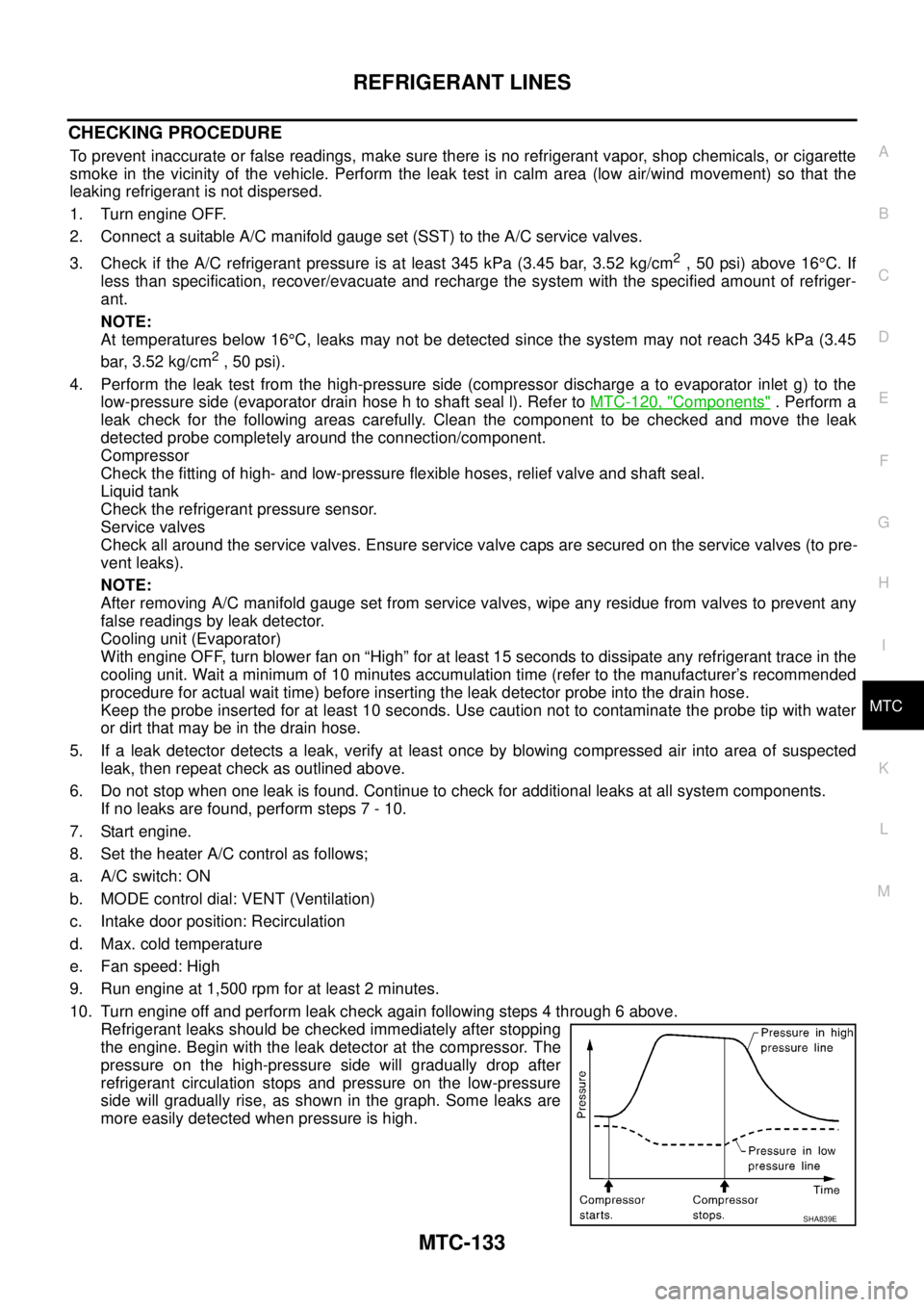
Refrigerant leaks should be checked immediately after stopping
the engine. Begin with the leak detector at the compressor. The
pressure on the high-pressure side will gradually drop after
refrigerant circulation stops and pressure on the low-pressure
side will gradually rise, as shown in the graph. Some leaks are
more easily detected when pressure is high.
SHA839E
Page 2544 of 3171
IPDM E/R (INTELLIGENT POWER DISTRIBUTION MODULE ENGINE ROOM)
PG-15
C
D
E
F
G
H
I
J
L
MA
B
PG
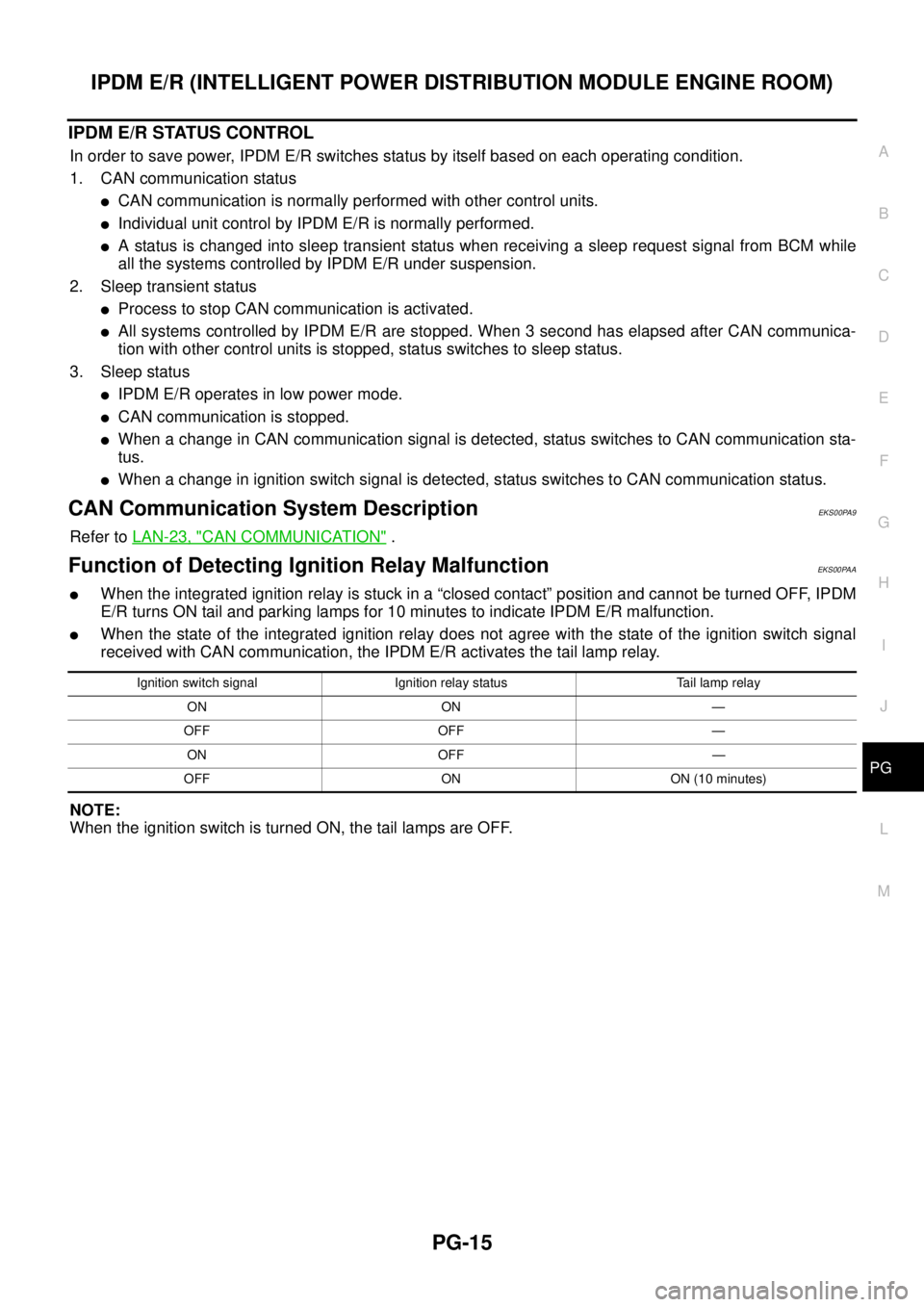
IPDM E/R STATUS CONTROL
In order to save power, IPDM E/R switches status by itself based on each operating condition.
1. CAN communication status
lCAN communication is normally performed with other control units.
lIndividual unit control by IPDM E/R is normally performed.
lA status is changed into sleep transient status when receiving a sleep request signal from BCM while
all the systems controlled by IPDM E/R under suspension.
2. Sleep transient status
lProcess to stop CAN communication is activated.
lAll systems controlled by IPDM E/R are stopped. When 3 second has elapsed after CAN communica-
tion with other control units is stopped, status switches to sleep status.
3. Sleep status
lIPDM E/R operates in low power mode.
lCAN communication is stopped.
lWhen a change in CAN communication signal is detected, status switches to CAN communication sta-
tus.
lWhen a change in ignition switch signal is detected, status switches to CAN communication status.
CAN Communication System DescriptionEKS00PA9
Refer toLAN-23, "CAN COMMUNICATION".
Function of Detecting Ignition Relay MalfunctionEKS00PAA
lWhen the integrated ignition relay is stuck in a “closed contact” position and cannot be turned OFF, IPDM
E/R turns ON tail and parking lamps for 10 minutes to indicate IPDM E/R malfunction.
lWhen the state of the integrated ignition relay does not agree with the state of the ignition switch signal
received with CAN communication, the IPDM E/R activates the tail lamp relay.
NOTE:
When the ignition switch is turned ON, the tail lamps are OFF.
Ignition switch signal Ignition relay status Tail lamp relay
ON ON —
OFF OFF —
ON OFF —
OFF ON ON (10 minutes)
Page 2547 of 3171

PG-18
IPDM E/R (INTELLIGENT POWER DISTRIBUTION MODULE ENGINE ROOM)
5. Touch “RECORD” while monitoring to record the status of the item being monitored. To stop recording,
touch “STOP”.
All Signals, Main Signals, Selection From Menu
NOTE:
Perform monitoring of IPDM E/R data with the ignition switch ON. When the ignition switch is in ACC position,
display may not be correct.
CAN DIAG SUPPORT MNTR
Refer toLAN-15, "CAN Diagnostic Support Monitor".
ACTIVE TEST
Operation Procedure
1. Touch “ACTIVE TEST” on “SELECT DIAG-MODE” screen.
2. Touch item to be tested, and check operation.
3. Touch “START”.
4. Touch “STOP” while testing to stop the operation.
Item nameCONSULT-II
screen displayDisplay or unitMonitor item selection
Description
ALL
SIGNALSMAIN
SIGNALSSELECTION
FROM MENU
Motor fan requestMOTOR FAN
REQ1/2/3/4 X X X Signal status input from ECM
A/C compressor
requestAC COMP REQ ON/OFF X X X Signal status input from ECM
Tail & clear
requestTAIL & CLR REQ ON/OFF X X X Signal status input from BCM
Headlamp LO
requestHL LO REQ ON/OFF X X X Signal status input from BCM
Headlamp HI
requestHL HI REQ ON/OFF X X X Signal status input from BCM
Front fog lamp
requestFR FOG REQ ON/OFF X X X Signal status input from BCM
Headlamp washer
requestHL WASHER
REQON/OFF X X Signal from input from BCM
Front wiper
requestFR WIP REQSTOP/1LOW/
LOW/HIX X X Signal status input from BCM
Wiper auto stopWIP AUTO
STOPACT P/STOP P X X X Output status of IPDM E/R
Wiper protection WIP PROT OFF/BLOCK X X X Control status of IPDM E/R
Starter request ST RLY REQ ON/OFF X X
Status of input signal
NOTE
Ignition relay
statusIGN RLY ON/OFF X X XIgnition relay status monitored
with IPDM E/R
Rear defogger
requestRR DEF REQ ON/OFF X X X Signal status input from BCM
Oil pressure
switchOIL P SW OPEN/CLOSE X XSignal status input from IPDM
E/R
Hood switch HOOD SW OFF XSignal status input from IPDM
E/R (function is not enabled)
Theft warning
horn requestTHFT HRN REQ ON/OFF X X Signal status input from BCM
Horn chirp HORN CHIRP ON/OFF X X Output status of IPDM E/R
Page 2548 of 3171
IPDM E/R (INTELLIGENT POWER DISTRIBUTION MODULE ENGINE ROOM)
PG-19
C
D
E
F
G
H
I
J
L
MA
B
PG
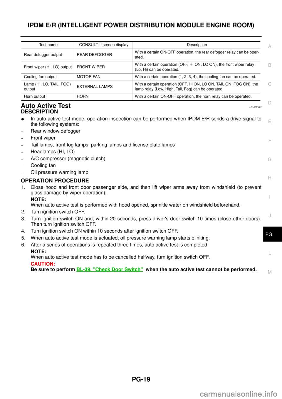
Auto Active TestEKS00PAC
DESCRIPTION
lIn auto active test mode, operation inspection can be performed when IPDM E/R sends a drive signal to
the following systems:
–Rear window defogger
–Front wiper
–Tail lamps, front fog lamps, parking lamps and license plate lamps
–Headlamps (HI, LO)
–A/C compressor (magnetic clutch)
–Cooling fan
–Oil pressure warning lamp
OPERATION PROCEDURE
1. Close hood and front door passenger side, and then lift wiper arms away from windshield (to prevent
glass damage by wiper operation).
NOTE:
When auto active test is performed with hood opened, sprinkle water on windshield beforehand.
2. Turn ignition switch OFF.
3. Turn ignition switch ON and, within 20 seconds, press driver's door switch 10 times (close other doors).
Then turn ignition switch OFF.
4. Turn ignition switch ON within 10 seconds after ignition switch OFF.
5. When auto active test mode is actuated, oil pressure warning lamp starts blinking.
6. After a series of operations is repeated three times, auto active test is completed.
NOTE:
When auto active test mode has to be cancelled halfway, turn ignition switch OFF.
CAUTION:
Be sure to performBL-39, "
Check Door Switch"when the auto active test cannot be performed.
Test name CONSULT-II screen display Description
Rear defogger output REAR DEFOGGERWith a certain ON-OFF operation, the rear defogger relay can be oper-
ated.
Front wiper (HI, LO) output FRONT WIPERWith a certain operation (OFF, HI ON, LO ON), the front wiper relay
(Lo, Hi) can be operated.
Cooling fan output MOTOR FAN With a certain operation (1, 2, 3, 4), the cooling fan can be operated.
Lamp (HI, LO, TAIL, FOG)
outputEXTERNAL LAMPSWith a certain operation (OFF, HI ON, LO ON, TAIL ON, FOG ON), the
lamp relay (Low, High, Tail, Fog) can be operated.
Horn output HORN With a certain ON-OFF operation, the horn relay can be operated.
Page 2549 of 3171
PG-20
IPDM E/R (INTELLIGENT POWER DISTRIBUTION MODULE ENGINE ROOM)
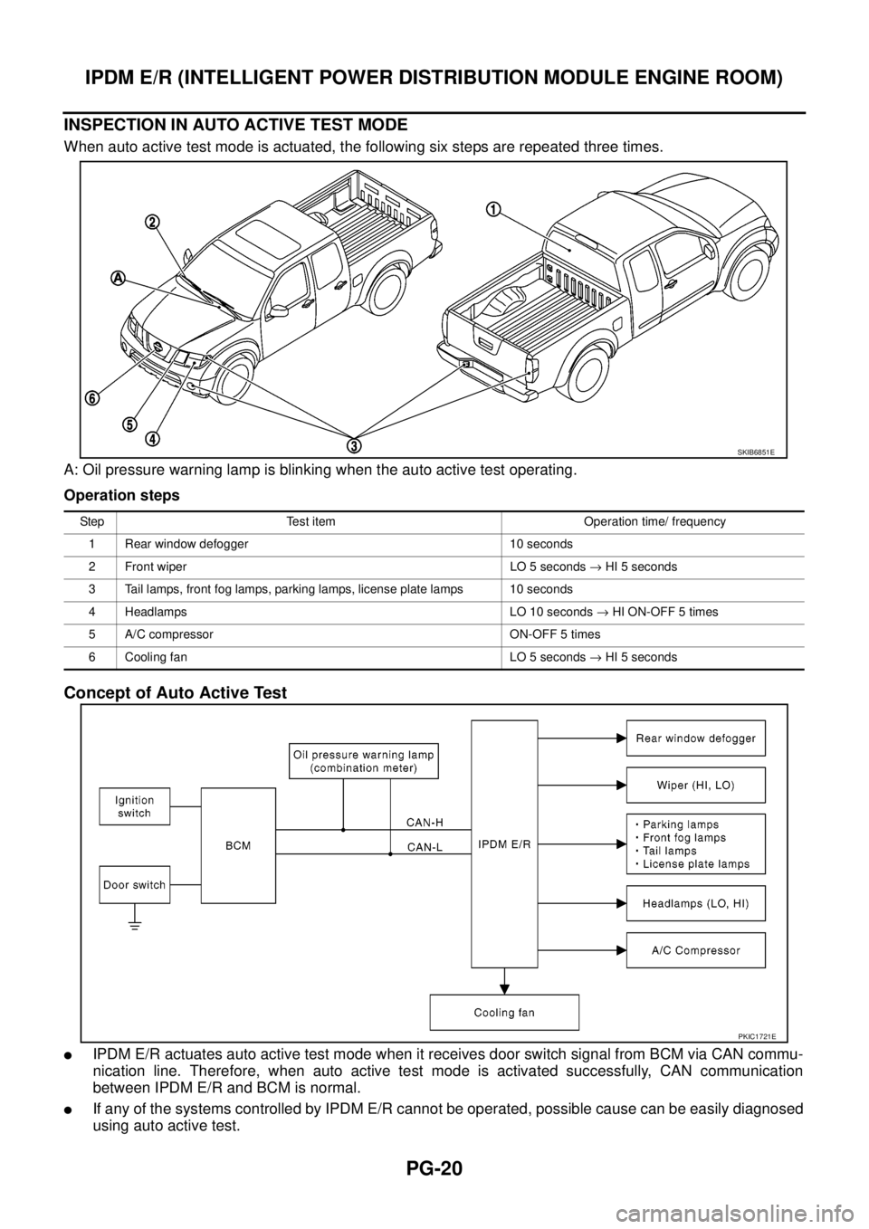
INSPECTION IN AUTO ACTIVE TEST MODE
When auto active test mode is actuated, the following six steps are repeated three times.
A: Oil pressure warning lamp is blinking when the auto active test operating.
Operation steps
Concept of Auto Active Test
lIPDM E/R actuates auto active test mode when it receives door switch signal from BCM via CAN commu-
nication line. Therefore, when auto active test mode is activated successfully, CAN communication
between IPDM E/R and BCM is normal.
lIf any of the systems controlled by IPDM E/R cannot be operated, possible cause can be easily diagnosed
using auto active test.
SKIB6851E
Step Test item Operation time/ frequency
1 Rear window defogger 10 seconds
2 Front wiper LO 5 seconds®HI 5 seconds
3 Tail lamps, front fog lamps, parking lamps, license plate lamps 10 seconds
4 Headlamps LO 10 seconds®HI ON-OFF 5 times
5 A/C compressor ON-OFF 5 times
6 Cooling fan LO 5 seconds®HI 5 seconds
PKIC1721E