2005 NISSAN NAVARA ECO mode
[x] Cancel search: ECO modePage 1669 of 3171

CONSULT-II CHECKING SYSTEM
GI-47
C
D
E
F
G
H
I
J
K
L
MB
GI
CONSULT-II CHECKING SYSTEMPFP:00000
DescriptionEAS001H2
lCONSULT-II is a hand-held type tester. When it is connected with a diagnostic connector equipped on the
vehicle side, it will communicate with the control unit equipped in the vehicle and then enable various
kinds of diagnostic tests.
lRefer to “CONSULT-II Software Operation Manual” for more information.
Function and System ApplicationEAS001H3
x: Applicable
*: Nissan Anti-Theft SystemDiagnostic test
modeFunction
ENGINE
A/T
AIR BAG
ABS
ALL MODE AWD/4WD
BCM
IPDM E/R
MULTI AV
METER
NATS *
Work supportThis mode enables a technician to adjust some devices
faster and more accurately by following the indications
on CONSULT-II.x---´´--- -
Self-diagnostic
resultsSelf-diagnostic results can be read and erased quickly. x x x x x´´´´x
Trouble diagnostic
recordCurrent self-diagnostic results and all trouble diagnostic
records previously stored can be read.--x------ -
Data monitor Input/Output data in the ECU can be read. x x - x x´´´´-
CAN diagnosis
support monitorThe communication condition of CAN communication
line can be indicated.xx - xx´´´´-
Active testDiagnostic Test Mode in which CONSULT-II drives some
actuators apart from the ECU and also shifts some
parameters in a specified range.x- -x-´´-- -
DTC confirmationThe results of SRT (System Readiness Test) and the
self-diagnosis status/result can be confirmed.x----- - -- -
DTC work supportThe operating condition to confirm Diagnosis Trouble
Codes can be selected.-x------- -
ECM (ECU/TCM)
part numberECM (ECU/TCM) part number can be read. x x - x x´-´--
ECU discrimi-
nated No.Classification number of a replacement ECU can be read
to prevent an incorrect ECU from being installed.--x------ -
Function testThis mode can show results of self-diagnosis of ECU
with either “OK” or “NG”. For engines, more practical
tests regarding sensor/switches and/or actuators are
available.xxxx-- - - - -
Control unit initial-
izationAll registered ignition key IDs in NATS components can
be initialized and new IDs can be registered.------ - -- x
AV C O M M m o n i t o rIndicates the communication condition of AV communi-
cation.- ----- -´--
ConfigurationThe vehicle configuration can be read and written on
brand-new ECU- ----´--- -
Page 1675 of 3171

TOW TRUCK TOWING
GI-53
C
D
E
F
G
H
I
J
K
L
MB
GI
TOW TRUCK TOWINGPFP:00000
To w Tr u c k To w i n gEAS001DI
WARNING:
lNever get under the vehicle while it is supported only by the jack. Always use safety stands to
support the frame when you have to get under the vehicle.
lPlace wheel chocks at both front and back of the wheels on the ground.
CAUTION:
lAll applicable local laws regarding the towing operation must be obeyed.
lIt is necessary to use proper towing equipment to avoid possible damage during towing opera-
tion. Towing is in accordance with Towing Procedure Manual at dealer.
lAlways attach safety chains before towing.
lWhen towing, make sure that the transmission, steering system and powertrain are in good order.
If any unit is damaged, dollies must be used.
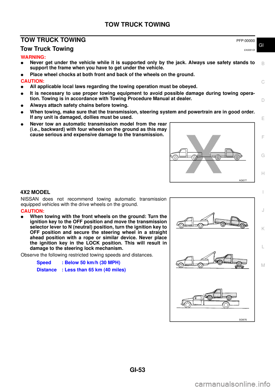
lNever tow an automatic transmission model from the rear
(i.e., backward) with four wheels on the ground as this may
cause serious and expensive damage to the transmission.
4X2 MODEL
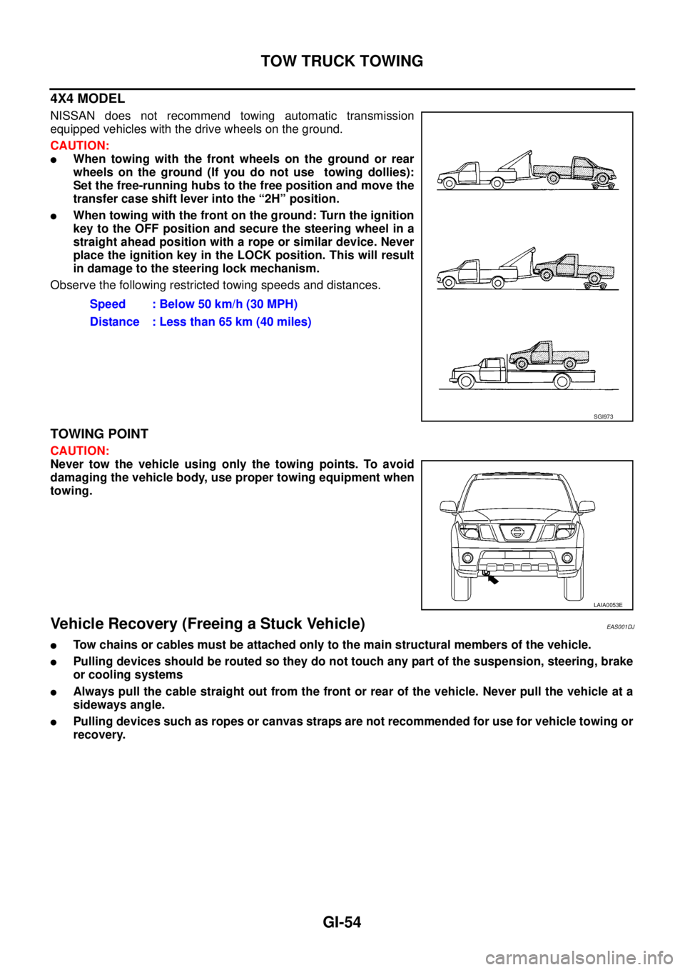
NISSAN does not recommend towing automatic transmission
equipped vehicles with the drive wheels on the ground.
CAUTION:
lWhen towing with the front wheels on the ground: Turn the
ignition key to the OFF position and move the transmission
selector lever to N (neutral) position, turn the ignition key to
OFF position and secure the steering wheel in a straight
ahead position with a rope or similar device. Never place
the ignition key in the LOCK position. This will result in
damage to the steering lock mechanism.
Observe the following restricted towing speeds and distances.
AGI077
Speed : Below 50 km/h (30 MPH)
Distance : Less than 65 km (40 miles)
SGI976
Page 1676 of 3171

GI-54
TOW TRUCK TOWING
4X4 MODEL
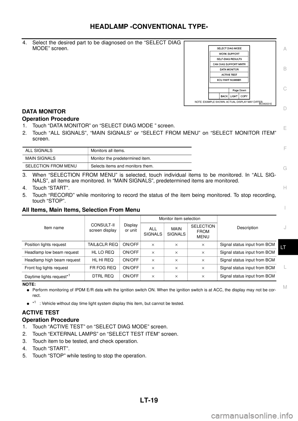
NISSAN does not recommend towing automatic transmission
equipped vehicles with the drive wheels on the ground.
CAUTION:
lWhen towing with the front wheels on the ground or rear
wheels on the ground (If you do not use towing dollies):
Set the free-running hubs to the free position and move the
transfer case shift lever into the “2H” position.
lWhen towing with the front on the ground: Turn the ignition
key to the OFF position and secure the steering wheel in a
straight ahead position with a rope or similar device. Never
place the ignition key in the LOCK position. This will result
in damage to the steering lock mechanism.
Observe the following restricted towing speeds and distances.
TOWING POINT
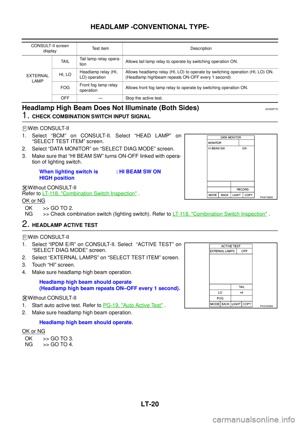
CAUTION:
Never tow the vehicle using only the towing points. To avoid
damaging the vehicle body, use proper towing equipment when
towing.
Vehicle Recovery (Freeing a Stuck Vehicle)EAS001DJ
lTow chains or cables must be attached only to the main structural members of the vehicle.
lPulling devices should be routed so they do not touch any part of the suspension, steering, brake
or cooling systems
lAlways pull the cable straight out from the front or rear of the vehicle. Never pull the vehicle at a
sideways angle.
lPulling devices such as ropes or canvas straps are not recommended for use for vehicle towing or
recovery.Speed : Below 50 km/h (30 MPH)
Distance : Less than 65 km (40 miles)
SGI973
LAIA0053E
Page 2099 of 3171

LT-16
HEADLAMP -CONVENTIONAL TYPE-
4. Touch “HEADLAMP” on “SELECT TEST ITEM” screen.
WORK SUPPORT
Operation Procedure
1. Touch “HEAD LAMP” on “SELECT TEST ITEM” screen.
2. Touch “WORK SUPPORT” on “SELECT DIAG MODE” screen.
3. Touch “HEAD LIGHT TIMER” on “SELECT WORK ITEM” screen.
4. Touch “START”.
5. Touch “MODE 1-2” of setting to be changed.
6. Touch “CHANGE SET”.
7. The setting will be changed and “CUSTOMIZING COMPLETED” will be displayed.
8. Touch “END”.
Work Support Setting Item
NOTE:
Factory setting
DATA MONITOR
Operation Procedure
1. Touch “HEADLAMP” on “SELECT TEST ITEM” screen.
2. Touch “DATA MONITOR” on “SELECT DIAG MODE” screen.
3. Touch either “ALL SIGNALS” or “SELECTION FROM MENU” on “DATA MONITOR” screen.
4. When “SELECTION FROM MENU” is selected, touch individual items to be monitored. When “ALL SIG-
NALS” is selected, all the items will be monitored.
5. Touch “START”.
6. Touch “RECORD” while monitoring, then the status of the monitored item can be recorded. To stop
recording, touch “STOP”.
Display Item List
PKIC0325E
Work item Description
HEAD LIGHT TIMERFriendly lighting function headlamp OFF timer period can be changed in this time. Selects friendly
lighting function headlamp OFF timer period two modes.
lMODE 1 (10sec.)/ MODE 2 (30sec.)NOTE
ALL SIGNALS Monitors all the signals.
SELECTION FROM MENU Selects items and monitors them.
Monitor item Contents
IGN ON SW “ON/OFF”Displays status (ignition switch IGN position: ON/other: OFF) of ignition switch judged from
the ignition switch signal.
ACCONSW “ON/OFF”Displays status (ignition switch ACC or IGN position: ON/other: OFF) of ignition switch judged
from the ignition switch signal.
HI BEAM SW “ON/OFF”Displays status (lighting switch high beam position: ON/other: OFF) of high beam switch
judged from the lighting switch signal.
Page 2102 of 3171

HEADLAMP -CONVENTIONAL TYPE-
LT-19
C
D
E
F
G
H
I
J
L
MA
B
LT
4. Select the desired part to be diagnosed on the “SELECT DIAG
MODE” screen.
DATA MONITOR
Operation Procedure
1. Touch “DATA MONITOR” on “SELECT DIAG MODE ” screen.
2. Touch “ALL SIGNALS”, “MAIN SIGNALS” or “SELECT FROM MENU” on “SELECT MONITOR ITEM”
screen.
3. When “SELECTION FROM MENU” is selected, touch individual items to be monitored. In “ALL SIG-
NALS”, all items are monitored. In “MAIN SIGNALS”, predetermined items are monitored.
4. Touch “START”.
5. Touch “RECORD” while monitoring to record the status of the item being monitored. To stop recording,
touch “STOP”.
All Items, Main Items, Selection From Menu
NOTE:
lPerform monitoring of IPDM E/R data with the ignition switch ON. When the ignition switch is at ACC, the display may not be cor-
rect.
l*1: Vehicle without day time light system display this item, but cannot be tested.
ACTIVE TEST
Operation Procedure
1. Touch “ACTIVE TEST” on “SELECT DIAG MODE” screen.
2. Touch “EXTERNAL LAMPS” on “SELECT TEST ITEM” screen.
3. Touch item to be tested, and check operation.
4. Touch “START”.
5. Touch “STOP” while testing to stop the operation.
BCIA0031E
ALL SIGNALS Monitors all items.
MAIN SIGNALS Monitor the predetermined item.
SELECTION FROM MENU Selects items and monitors them.
Item nameCONSULT-II
screen displayDisplay
or unitMonitor item selection
Description
ALL
SIGNALSMAIN
SIGNALSSELECTION
FROM
MENU
Position lights request TAIL&CLR REQ ON/OFF´´ ´Signal status input from BCM
Headlamp low beam request HL LO REQ ON/OFF´´ ´Signal status input from BCM
Headlamp high beam request HL HI REQ ON/OFF´´ ´Signal status input from BCM
Front fog lights request FR FOG REQ ON/OFF´´ ´Signal status input from BCM
Daytime lights request*
1DTRL REQ ON/OFF´´ ´Signal status input from BCM
Page 2103 of 3171

LT-20
HEADLAMP -CONVENTIONAL TYPE-
Headlamp High Beam Does Not Illuminate (Both Sides)
EKS00P7S
1.CHECK COMBINATION SWITCH INPUT SIGNAL
With CONSULT-II
1. Select “BCM” on CONSULT-II. Select “HEAD LAMP” on
“SELECT TEST ITEM” screen.
2. Select “DATA MONITOR” on “SELECT DIAG MODE” screen.
3. Make sure that “HI BEAM SW” turns ON-OFF linked with opera-
tion of lighting switch.
Without CONSULT-II
Refer toLT- 11 8 , "
Combination Switch Inspection".
OK or NG
OK >> GO TO 2.
NG >> Check combination switch (lighting switch). Refer toLT- 11 8 , "
Combination Switch Inspection".
2.HEADLAMP ACTIVE TEST
With CONSULT-II
1. Select “IPDM E/R” on CONSULT-II. Select “ACTIVE TEST” on
“SELECT DIAG MODE” screen.
2. Select “EXTERNAL LAMPS” on “SELECT TEST ITEM” screen.
3. Touch “HI” screen.
4. Make sure headlamp high beam operation.
Without CONSULT-II
1. Start auto active test. Refer toPG-19, "
Auto Active Test".
2. Make sure headlamp high beam operation.
OK or NG
OK >> GO TO 3.
NG >> GO TO 4.
CONSULT-II screen
displayTest item Description
EXTERNAL
LAMPTA I LTail lamp relay opera-
tionAllows tail lamp relay to operate by switching operation ON.
HI, LOHeadlamp relay (HI,
LO) operationAllows headlamp relay (HI, LO) to operate by switching operation (HI, LO) ON.
(Headlamp highbeam repeats ON-OFF every 1 second)
FOGFront fog lamp relay
operationAllows front fog lamp relay to operate by switching operation ON.
OFF — Stop the active test.
When lighting switch is
HIGH position: HI BEAM SW ON
PKIA7585E
Headlamp high beam should operate
(Headlamp high beam repeats ON–OFF every 1 second).
Headlamp high beam should operate.
PKIC0936E
Page 2126 of 3171

HEADLAMP - DAYTIME LIGHT SYSTEM -
LT-43
C
D
E
F
G
H
I
J
L
MA
B
LT
4. Touch “HEAD LAMP” on “SELECT TEST ITEM” screen.
DATA MONITOR
Operation Procedure
1. Touch “HEAD LAMP” on “SELECT TEST ITEM” screen.
2. Touch “DATA MONITOR” on “SELECT DIAG MODE” screen.
3. Touch either “ALL SIGNALS” or “SELECTION FROM MENU” on “SELECT MONITOR ITEM” screen.
4. When “SELECTION FROM MENU” is selected, touch individual items to be monitored. When “ALL SIG-
NALS” is selected, all the items will be monitored.
5. Touch “START”.
6. Touch “RECORD” while monitoring, then the status of the monitored item can be recorded. To stop
recording, touch “STOP”.
Display Item List
PKIB2726E
ALL SIGNALS Monitors all the signals.
SELECTION FROM MENU Selects items and monitor them.
Monitor item Contents
IGN ON SW “ON/OFF”Displays status (ignition switch IGN position: ON/other: OFF) of ignition switch judged from
the ignition switch signal.
ACC ON SW “ON/OFF”Displays status (ignition switch ACC or IGN position: ON/other: OFF) of ignition switch judged
from the ignition switch signal.
HI BEAM SW “ON/OFF”Displays status (lighting switch high beam position: ON/other: OFF) of high beam switch
judged from the lighting switch signal.
HEAD LAMP SW 1 “ON/OFF”Displays status (lighting switch 2ND position: ON/other: OFF) of headlamp 1 switch judged
from the lighting switch signal.
HEAD LAMP SW 2 “ON/OFF”Displays status (lighting switch 2ND position: ON/other: OFF) of headlamp 2 switch judged
from the lighting switch signal.
LIGHT SW 1ST “ON/OFF”Displays status (lighting switch 1ST or 2ND position: ON/other: OFF) of lighting switch 1ST
position switch judged from the lighting switch signal.
PASSING SW “ON/OFF”Displays status (lighting switch passing position: ON/other: OFF) of passing switch judged
from the lighting switch signal.
FR FOG SW “ON/OFF”Displays status (lighting switch front fog lamp ON position: ON/others: OFF) of front fog lamp
switch judged from the lighting switch signal.
RR FOG SW “ON/OFF”Displays status (lighting switch rear fog lamp ON position: ON/others: OFF) of rear fog lamp
switch judged from the lighting switch signal.
DOOR SW - DR “ON/OFF”Displays status (door is open: ON/door is closed: OFF) of driver side door switch judged from
the driver side door switch signal.
DOOR SW - AS “ON/OFF”Displays status (door is open: ON/door is closed: OFF) of passenger side door switch judged
from the passenger side door switch signal.
DOOR SW - RR “ON/OFF”Displays status (door is open: ON/door is closed: OFF) of rear door switch (RH) judged from
the rear door switch (RH) signal.
DOOR SW - RL “ON/OFF”Displays status (door is open: ON/door is closed: OFF) of rear door switch (LH) judged from
the rear door switch (LH) signal.
Page 2129 of 3171

LT-46
HEADLAMP - DAYTIME LIGHT SYSTEM -
4. Select the desired part to be diagnosed on “SELECT DIAG
MODE” screen.
DATA MONITOR
Operation Procedure
1. Touch “DATA MONITOR” on “SELECT DIAG MODE ” screen.
2. Touch “ALL SIGNALS”, “MAIN SIGNALS” or “SELECTION FROM MENU” on “SELECT MONITOR ITEM”
screen.
3. When “SELECTION FROM MENU” is selected, touch individual items to be monitored. In “ALL SIG-
NALS”, all items are monitored. In “MAIN SIGNALS”, predetermined items are monitored.
4. Touch “START”.
5. Touch “RECORD” while monitoring to record the status of the item being monitored. To stop recording,
touch “STOP”.
All Signals, Main Signals, Selection From Menu
NOTE:
Perform monitoring of IPDM E/R data with the ignition switch ON. When the ignition switch is at ACC, the display may not be correct.
ACTIVE TEST
Operation Procedure
1. Touch “ACTIVE TEST” on “SELECT DIAG MODE” screen.
2. Touch “EXTERNAL LAMPS” on “SELECT TEST ITEM” screen.
3. Touch item to be tested, and check operation.
4. Touch “START”.
5. Touch “OFF” while testing to stop the operation.
BCIA0031E
ALL SIGNALS Monitors all items.
MAIN SIGNALS Monitor the predetermined item.
SELECTION FROM MENU Selects items and monitors them.
Item nameCONSULT-II
screen displayDisplayMonitor item selection
Description
ALL
SIGNALSMAIN
SIGNALSSELECTION
FROM MENU
Position lights requestTA I L & C L R
REQON/OFF´´ ´Signal status input from BCM
Headlamp low beam request HL LO REQ ON/OFF´´ ´Signal status input from BCM
Headlamp high beam request HL HI REQ ON/OFF´´ ´Signal status input from BCM
Front fog lights request FR FOG REQ ON/OFF´´ ´Signal status input from BCM
Daytime light request DTRL REQ ON/OFF´´ ´Signal status input from BCM