2005 NISSAN NAVARA ECO mode
[x] Cancel search: ECO modePage 1412 of 3171
EM-30
TURBO CHARGER
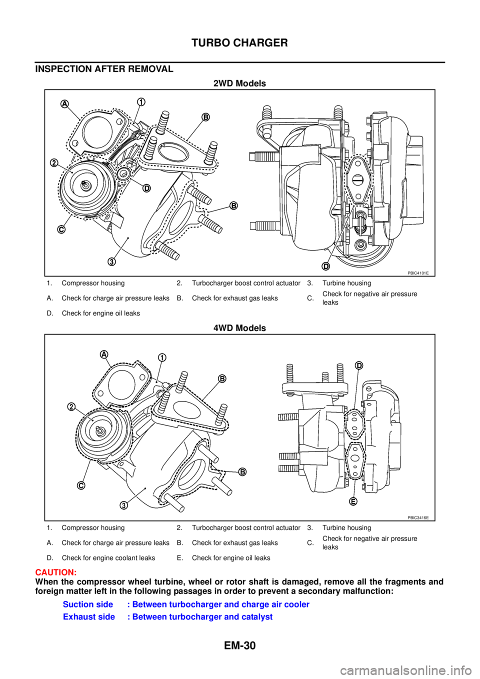
INSPECTION AFTER REMOVAL
2WD Models
4WD Models
CAUTION:
When the compressor wheel turbine, wheel or rotor shaft is damaged, remove all the fragments and
foreign matter left in the following passages in order to prevent a secondary malfunction:
PBIC4101E
1. Compressor housing 2. Turbocharger boost control actuator 3. Turbine housing
A. Check for charge air pressure leaks B. Check for exhaust gas leaks C.Check for negative air pressure
leaks
D. Check for engine oil leaks
PBIC3416E
1. Compressor housing 2. Turbocharger boost control actuator 3. Turbine housing
A. Check for charge air pressure leaks B. Check for exhaust gas leaks C.Check for negative air pressure
leaks
D. Check for engine coolant leaks E. Check for engine oil leaks
Suction side : Between turbocharger and charge air cooler
Exhaust side : Between turbocharger and catalyst
Page 1429 of 3171
INJECTION TUBE AND FUEL INJECTOR
EM-47
C
D
E
F
G
H
I
J
K
L
MA
EM
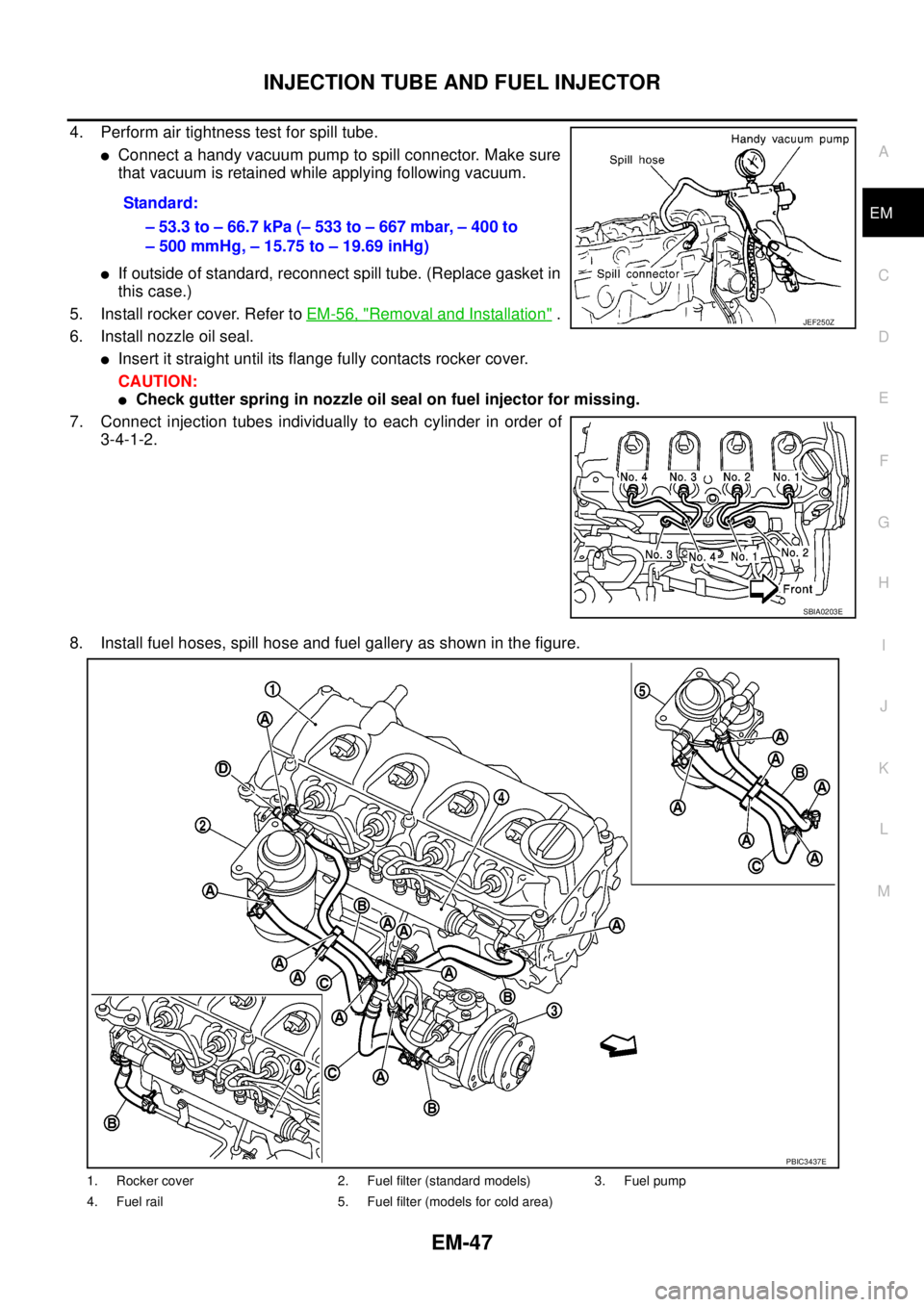
4. Perform air tightness test for spill tube.
lConnect a handy vacuum pump to spill connector. Make sure
that vacuum is retained while applying following vacuum.
lIf outside of standard, reconnect spill tube. (Replace gasket in
this case.)
5. Install rocker cover. Refer toEM-56, "
Removal and Installation".
6. Install nozzle oil seal.
lInsert it straight until its flange fully contacts rocker cover.
CAUTION:
lCheck gutter spring in nozzle oil seal on fuel injector for missing.
7. Connect injection tubes individually to each cylinder in order of
3-4-1-2.
8. Install fuel hoses, spill hose and fuel gallery as shown in the figure.Standard:
–53.3to–66.7kPa(–533to–667mbar,–400to
– 500 mmHg, – 15.75 to – 19.69 inHg)
JEF250Z
SBIA0203E
1. Rocker cover 2. Fuel filter (standard models) 3. Fuel pump
4. Fuel rail 5. Fuel filter (models for cold area)
PBIC3437E
Page 1455 of 3171
SECONDARY TIMING CHAIN
EM-73
C
D
E
F
G
H
I
J
K
L
MA
EM
SECONDARY TIMING CHAINPFP:13028
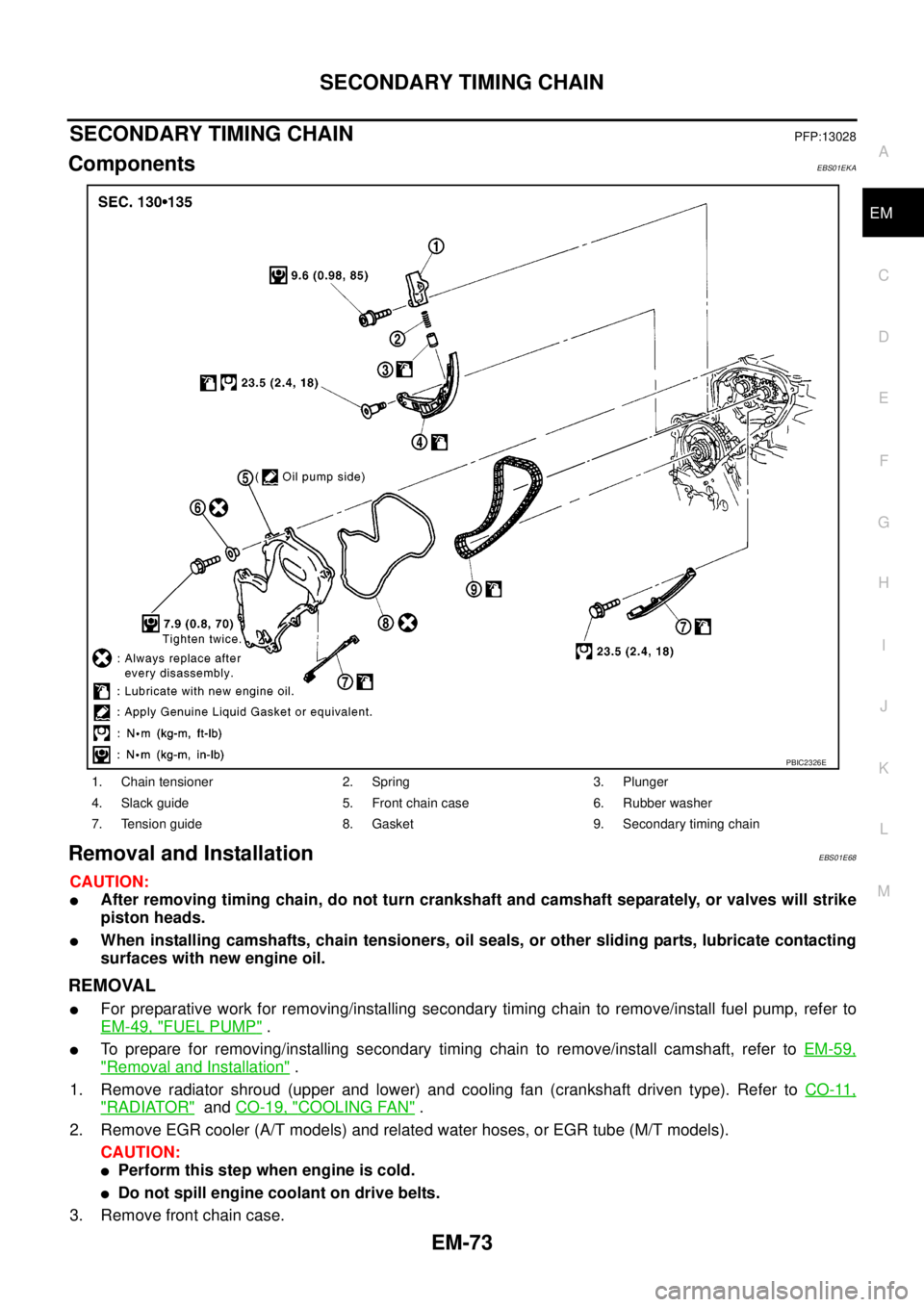
ComponentsEBS01EKA
Removal and InstallationEBS01E68
CAUTION:
lAfter removing timing chain, do not turn crankshaft and camshaft separately, or valves will strike
piston heads.
lWhen installing camshafts, chain tensioners, oil seals, or other sliding parts, lubricate contacting
surfaces with new engine oil.
REMOVAL
lFor preparative work for removing/installing secondary timing chain to remove/install fuel pump, refer to
EM-49, "
FUEL PUMP".
lTo prepare for removing/installing secondary timing chain to remove/install camshaft, refer toEM-59,
"Removal and Installation".
1. Remove radiator shroud (upper and lower) and cooling fan (crankshaft driven type). Refer toCO-11,
"RADIATOR"andCO-19, "COOLING FAN".
2. Remove EGR cooler (A/T models) and related water hoses, or EGR tube (M/T models).
CAUTION:
lPerform this step when engine is cold.
lDo not spill engine coolant on drive belts.
3. Remove front chain case.
1. Chain tensioner 2. Spring 3. Plunger
4. Slack guide 5. Front chain case 6. Rubber washer
7. Tension guide 8. Gasket 9. Secondary timing chain
PBIC2326E
Page 1462 of 3171
EM-80
PRIMARY TIMING CHAIN
lRefer toGI-10, "Components"for symbol marks in the figure.
Removal and InstallationEBS01E69
CAUTION:
lAfter removing timing chain, do not turn crankshaft and camshaft separately, or valves will strike
piston heads.
lWhen installing camshafts, chain tensioners, oil seals or other sliding parts, lubricate contacting
surfaces with new engine oil.
REMOVAL
1. Remove power steering oil pump and power steering oil pump bracket. Refer toPS-25, "POWER STEER-
ING OIL PUMP".
2. Remove idler pulleys.
3. Remove rocker cover. Refer toEM-56, "
ROCKER COVER".
4. Remove oil pan (upper and lower). Refer toEM-36, "
OIL PAN AND OIL STRAINER".
5. Remove fuel injector. Refer toEM-44, "
INJECTION TUBE AND FUEL INJECTOR".
6. Remove secondary timing chain and associated parts. Refer toEM-73, "
SECONDARY TIMING CHAIN".
7. When removing rear chain case, remove camshaft sprockets. Refer toEM-59, "
CAMSHAFT".
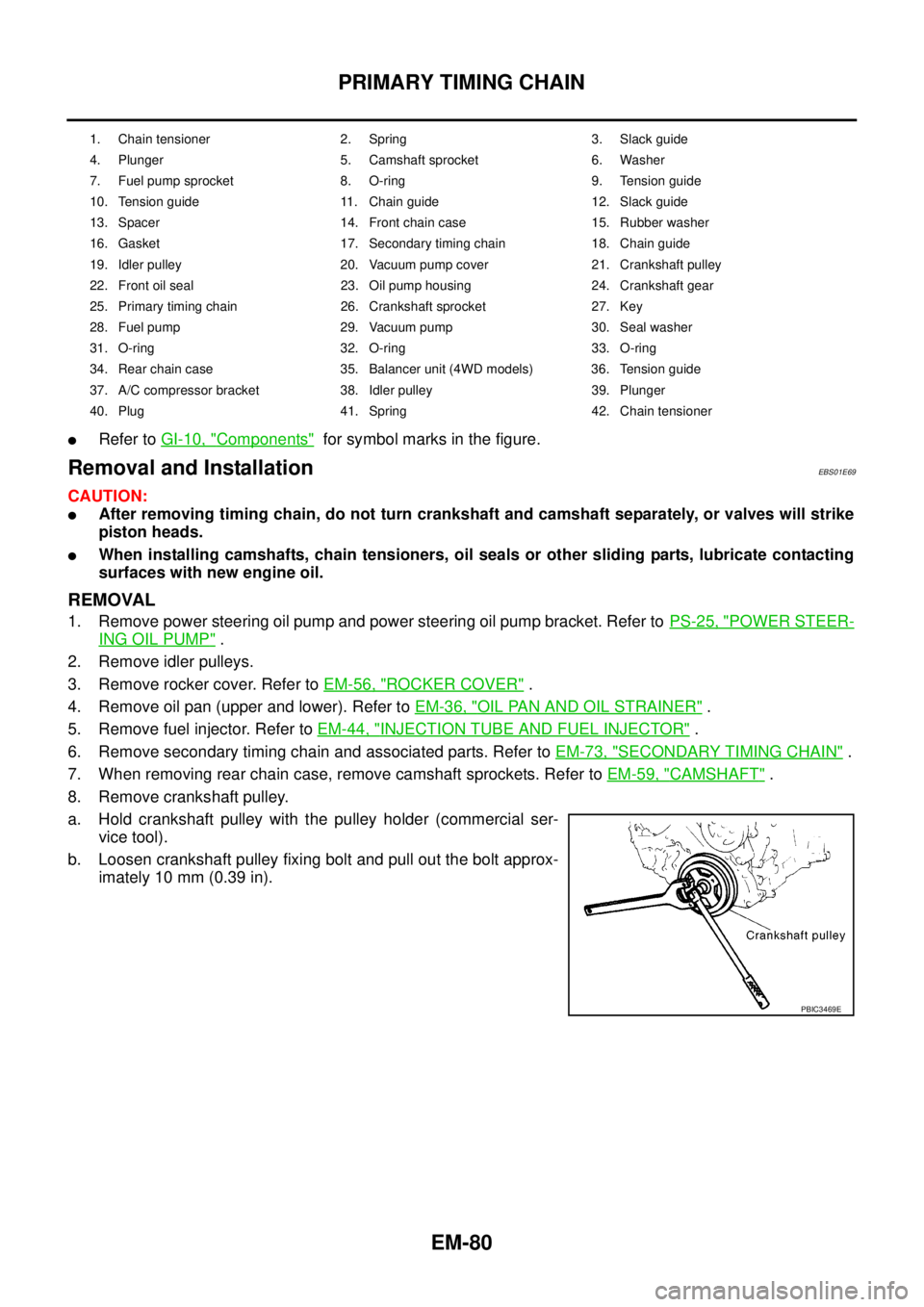
8. Remove crankshaft pulley.
a. Hold crankshaft pulley with the pulley holder (commercial ser-
vice tool).
b. Loosen crankshaft pulley fixing bolt and pull out the bolt approx-
imately 10 mm (0.39 in).
1. Chain tensioner 2. Spring 3. Slack guide
4. Plunger 5. Camshaft sprocket 6. Washer
7. Fuel pump sprocket 8. O-ring 9. Tension guide
10. Tension guide 11. Chain guide 12. Slack guide
13. Spacer 14. Front chain case 15. Rubber washer
16. Gasket 17. Secondary timing chain 18. Chain guide
19. Idler pulley 20. Vacuum pump cover 21. Crankshaft pulley
22. Front oil seal 23. Oil pump housing 24. Crankshaft gear
25. Primary timing chain 26. Crankshaft sprocket 27. Key
28. Fuel pump 29. Vacuum pump 30. Seal washer
31. O-ring 32. O-ring 33. O-ring
34. Rear chain case 35. Balancer unit (4WD models) 36. Tension guide
37. A/C compressor bracket 38. Idler pulley 39. Plunger
40. Plug 41. Spring 42. Chain tensioner
PBIC3469E
Page 1467 of 3171
PRIMARY TIMING CHAIN
EM-85
C
D
E
F
G
H
I
J
K
L
MA
EM
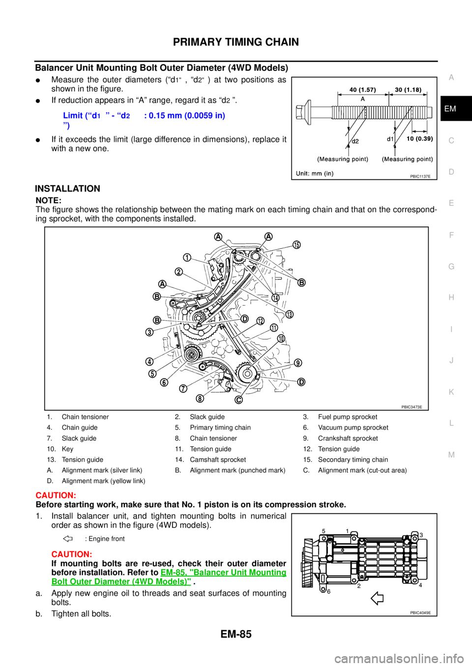
Balancer Unit Mounting Bolt Outer Diameter (4WD Models)
lMeasure the outer diameters (“d1”,“d2”)attwopositionsas
showninthefigure.
lIf reduction appears in “A” range, regard it as “d2”.
lIf it exceeds the limit (large difference in dimensions), replace it
with a new one.
INSTALLATION
NOTE:
The figure shows the relationship between the mating mark on each timing chain and that on the correspond-
ing sprocket, with the components installed.
CAUTION:
Before starting work, make sure that No. 1 piston is on its compression stroke.
1. Install balancer unit, and tighten mounting bolts in numerical
order as shown in the figure (4WD models).
CAUTION:
If mounting bolts are re-used, check their outer diameter
before installation. Refer toEM-85, "
Balancer Unit Mounting
Bolt Outer Diameter (4WD Models)".
a. Apply new engine oil to threads and seat surfaces of mounting
bolts.
b. Tighten all bolts.Limit (“d
1”-“d2
”): 0.15 mm (0.0059 in)
PBIC1137E
1. Chain tensioner 2. Slack guide 3. Fuel pump sprocket
4. Chain guide 5. Primary timing chain 6. Vacuum pump sprocket
7. Slack guide 8. Chain tensioner 9. Crankshaft sprocket
10. Key 11. Tension guide 12. Tension guide
13. Tension guide 14. Camshaft sprocket 15. Secondary timing chain
A. Alignment mark (silver link) B. Alignment mark (punched mark) C. Alignment mark (cut-out area)
D. Alignment mark (yellow link)
: Engine front
PBIC3473E
PBIC4049E
Page 1493 of 3171
CYLINDER BLOCK
EM-111
C
D
E
F
G
H
I
J
K
L
MA
EM
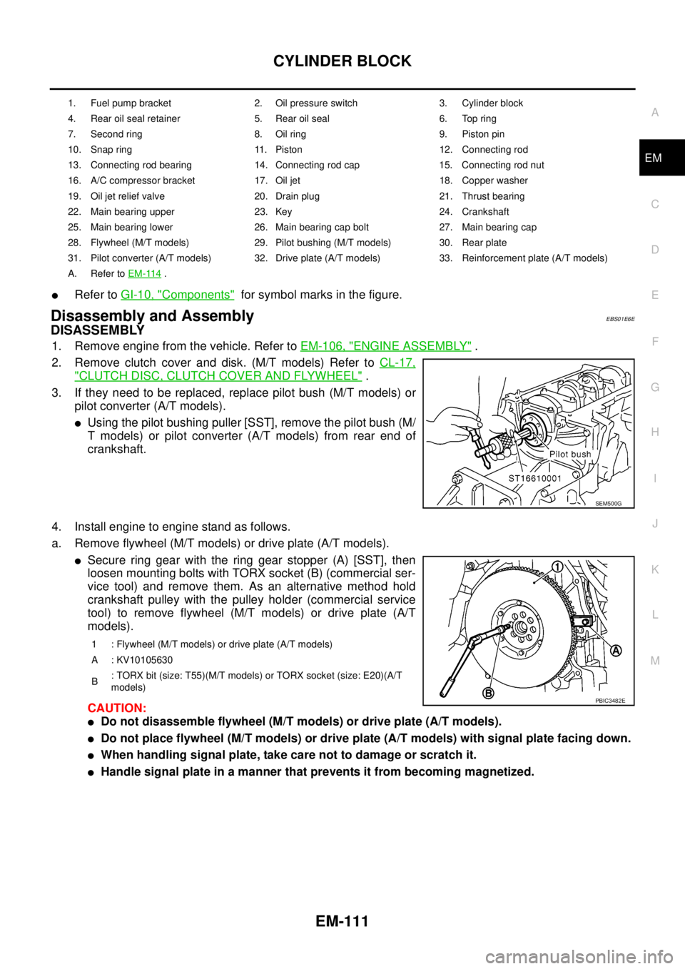
lRefer toGI-10, "Components"for symbol marks in the figure.
Disassembly and AssemblyEBS01E6E
DISASSEMBLY
1. Remove engine from the vehicle. Refer toEM-106, "ENGINE ASSEMBLY".
2. Remove clutch cover and disk. (M/T models) Refer toCL-17,
"CLUTCH DISC, CLUTCH COVER AND FLYWHEEL".
3. If they need to be replaced, replace pilot bush (M/T models) or
pilot converter (A/T models).
lUsing the pilot bushing puller [SST], remove the pilot bush (M/
T models) or pilot converter (A/T models) from rear end of
crankshaft.
4. Install engine to engine stand as follows.
a. Remove flywheel (M/T models) or drive plate (A/T models).
lSecure ring gear with the ring gear stopper (A) [SST], then
loosen mounting bolts with TORX socket (B) (commercial ser-
vice tool) and remove them. As an alternative method hold
crankshaft pulley with the pulley holder (commercial service
tool) to remove flywheel (M/T models) or drive plate (A/T
models).
CAUTION:
lDo not disassemble flywheel (M/T models) or drive plate (A/T models).
lDo not place flywheel (M/T models) or drive plate (A/T models) with signal plate facing down.
lWhen handling signal plate, take care not to damage or scratch it.
lHandle signal plate in a manner that prevents it from becoming magnetized.
1. Fuel pump bracket 2. Oil pressure switch 3. Cylinder block
4. Rear oil seal retainer 5. Rear oil seal 6. Top ring
7. Second ring 8. Oil ring 9. Piston pin
10. Snap ring 11. Piston 12. Connecting rod
13. Connecting rod bearing 14. Connecting rod cap 15. Connecting rod nut
16. A/C compressor bracket 17. Oil jet 18. Copper washer
19. Oil jet relief valve 20. Drain plug 21. Thrust bearing
22. Main bearing upper 23. Key 24. Crankshaft
25. Main bearing lower 26. Main bearing cap bolt 27. Main bearing cap
28. Flywheel (M/T models) 29. Pilot bushing (M/T models) 30. Rear plate
31. Pilot converter (A/T models) 32. Drive plate (A/T models) 33. Reinforcement plate (A/T models)
A. Refer toEM-114
.
SEM500G
1 : Flywheel (M/T models) or drive plate (A/T models)
A : KV10105630
B: TORX bit (size: T55)(M/T models) or TORX socket (size: E20)(A/T
models)
PBIC3482E
Page 1623 of 3171
GI-1
GENERAL INFORMATION
A GENERAL INFORMATION
CONTENTS
C
D
E
F
G
H
I
J
K
L
MB
GI
SECTIONGI
GENERAL INFORMATION
PRECAUTIONS .......................................................... 3
Description ............................................................... 3
Precautions for Supplemental Restraint System
(SRS)“AIRBAG”and“SEATBELTPRE-TEN-
SIONER” .................................................................. 3
Precautions for NATS (NISSAN ANTI-THEFT SYS-
TEM) ........................................................................ 3
Precautions Necessary for Steering Wheel Rotation
After Battery Disconnect .......................................... 3
OPERATION PROCEDURE ................................. 4
General Precautions ................................................ 4
Precautions for Three Way Catalyst ......................... 5
Precautions for Fuel ................................................. 5
GASOLINE ENGINE ............................................. 5
DIESEL ENGINE ................................................... 6
Precautions for Multiport Fuel Injection System or
Engine Control System ............................................ 6
Precautions for Turbocharger (If Equipped) ............. 6
Precautions for Hoses .............................................. 6
HOSE REMOVAL AND INSTALLATION ............... 6
HOSE CLAMPING ................................................ 7
Precautions for Engine Oils ...................................... 7
HEALTH PROTECTION PRECAUTIONS ............. 7
ENVIRONMENTAL PROTECTION PRECAU-
TIONS ................................................................... 8
Precautions for Air Conditioning ............................... 8
HOW TO USE THIS MANUAL ................................... 9
Description ............................................................... 9
Terms ....................................................................... 9
Units ......................................................................... 9
Contents ................................................................... 9
Components ........................................................... 10
SYMBOLS ........................................................... 10
How to Follow Trouble Diagnoses ........................... 11
DESCRIPTION ..................................................... 11
HOW TO FOLLOW TEST GROUPS IN TROU-
BLE DIAGNOSES ................................................ 11
HARNESS WIRE COLOR AND CONNECTOR
NUMBER INDICATION ....................................... 12
KEY TO SYMBOLS SIGNIFYING MEASURE-MENTS OR PROCEDURES ............................... 13
How to Read Wiring Diagrams ............................... 15
CONNECTOR SYMBOLS ................................... 15
SAMPLE/WIRING DIAGRAM - EXAMPL - .......... 16
DESCRIPTION .................................................... 17
Abbreviations .......................................................... 23
SERVICE INFORMATION FOR ELECTRICAL INCI-
DENT ......................................................................... 24
How to Perform Efficient Diagnosis for an Electrical
Incident ................................................................... 24
WORK FLOW ...................................................... 24
INCIDENT SIMULATION TESTS ........................ 24
CIRCUIT INSPECTION ....................................... 27
Control Units and Electrical Parts ........................... 32
PRECAUTIONS .................................................. 32
CONTROL UNIT CONFIGURATION PROCEDURE... 34
Description .............................................................. 34
Part Replacement procedure Reference Table ...... 34
Work Procedure ...................................................... 36
Configuration (BCM) ............................................... 37
DESCRIPTION .................................................... 37
READ CONFIGURATION PROCEDURE ............ 37
WRITE CONFIGURATION PROCEDURE .......... 41
CONSULT-II CHECKING SYSTEM .......................... 47
Description .............................................................. 47
Function and System Application ........................... 47
Nickel Metal Hydride Battery Replacement ............ 48
Checking Equipment .............................................. 49
CONSULT-II Start Procedure .................................. 49
CONSULT-II Data Link Connector (DLC) Circuit .... 50
INSPECTION PROCEDURE .............................. 51
LIFTING POINT ......................................................... 52
Pantograph Jack, Garage Jack and Safety Stand... 52
2-Pole Lift ............................................................... 52
TOW TRUCK TOWING ............................................. 53
Tow Truck Towing ................................................... 53
4X2 MODEL ........................................................ 53
4X4 MODEL ........................................................ 54
TOWING POINT .................................................. 54
Vehicle Recovery (Freeing a Stuck Vehicle) ........... 54
Page 1625 of 3171
PRECAUTIONS
GI-3
C
D
E
F
G
H
I
J
K
L
MB
GI
PRECAUTIONSPFP:00001
DescriptionEAS001GG
Observe the following precautions to ensure safe and proper servicing. These precautions are not
described in each individual section.
Precautions for Supplemental Restraint System (SRS) “AIR BAG” and “SEAT
BELT PRE-TENSIONER”
EAS001GH
The Supplemental Restraint System such as “AIR BAG” and “SEAT BELT PRE-TENSIONER”, used along
with a front seat belt, helps to reduce the risk or severity of injury to the driver and front passenger for certain
types of collision. Information necessary to service the system safely is included in the SRS and SB section of
this Service Manual.
WARNING:
lTo avoid rendering the SRS inoperative, which could increase the risk of personal injury or death
in the event of a collision which would result in air bag inflation, all maintenance must be per-
formed by an authorized NISSAN/INFINITI dealer.
lImproper maintenance, including incorrect removal and installation of the SRS, can lead to per-
sonal injury caused by unintentional activation of the system. For removal of Spiral Cable and Air
Bag Module, see the SRS section.
lDo not use electrical test equipment on any circuit related to the SRS unless instructed to in this
Service Manual. SRS wiring harnesses can be identified by yellow and/or orange harnesses or
harness connectors.
Precautions for NATS (NISSAN ANTI-THEFT SYSTEM)EAS001GI
NATS will immobilize the engine if someone tries to start it without the registered key of NATS.
Both of the originally supplied ignition key IDs have been NATS registered.
The security indicator is located on the instrument panel. The indicator blinks when the immobilizer system is
functioning.
Therefore, NATS warns outsiders that the vehicle is equipped with the anti-theft system.
lWhen NATS detects trouble, the security indicator lamp lights up while ignition switch is in "ON" position.
This lighting up indicates that the anti-theft is not functioning, so prompt service is required.
lWhen servicing NATS (trouble diagnoses, system initialization and additional registration of other NATS
ignition key IDs), CONSULT-II hardware and CONSULT-II NATS software is necessary.
Regarding the procedures of NATS initialization and NATS ignition key ID registration, refer to CONSULT-
II operation manual, NATS.
Therefore, CONSULT-II NATS software (program card and operation manual) must be kept strictly con-
fidential to maintain the integrity of the anti-theft function.
lWhen servicing NATS (trouble diagnoses, system initialization and additional registration of other NATS
ignition key IDs), it may be necessary to re-register original key identification. Therefore, be sure to
receive all keys from vehicle owner. A maximum of four or five key IDs can be registered into NATS.
lWhen failing to start the engine first time using the key of NATS, start as follows.
1. Leave the ignition key in "ON" position for approximately 5 seconds.
2. Turn ignition key to "OFF" or "LOCK" position and wait approximately 5 seconds.
3. Repeat step 1 and 2 again.
4. Restart the engine while keeping the key separate from any others on key-chain.
Precautions Necessary for Steering Wheel Rotation After Battery DisconnectEAS001HY
NOTE:
lThis Procedure is applied only to models with Intelligent Key system and NATS (NISSAN ANTI-THEFT
SYSTEM).
lRemove and install all control units after disconnecting both battery cables with the ignition knob in the
²LOCK²position.
lAlways use CONSULT-II to perform self-diagnosis as a part of each function inspection after finishing
work. If DTC is detected, perform trouble diagnosis according to self-diagnostic results.
For models equipped with the Intelligent Key system and NATS, an electrically controlled steering lock mech-
anism is adopted on the key cylinder.