Page 1232 of 3171
EC-252
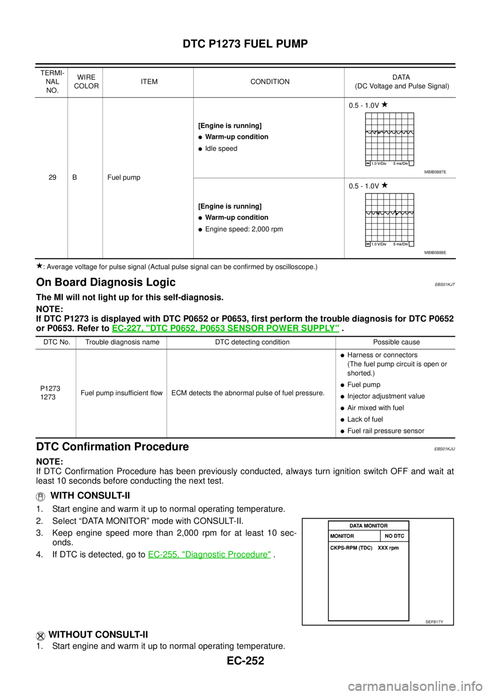
DTC P1273 FUEL PUMP
: Average voltage for pulse signal (Actual pulse signal can be confirmed by oscilloscope.)
On Board Diagnosis LogicEBS01KJT
The MI will not light up for this self-diagnosis.
NOTE:
If DTC P1273 is displayed with DTC P0652 or P0653, first perform the trouble diagnosis for DTC P0652
or P0653. Refer toEC-227, "
DTC P0652, P0653 SENSOR POWER SUPPLY".
DTC Confirmation ProcedureEBS01KJU
NOTE:
If DTC Confirmation Procedure has been previously conducted, always turn ignition switch OFF and wait at
least 10 seconds before conducting the next test.
WITH CONSULT-II
1. Start engine and warm it up to normal operating temperature.
2. Select “DATA MONITOR” mode with CONSULT-II.
3. Keep engine speed more than 2,000 rpm for at least 10 sec-
onds.
4. If DTC is detected, go toEC-255, "
Diagnostic Procedure".
WITHOUT CONSULT-II
1. Start engine and warm it up to normal operating temperature.
29 B Fuel pump[Engine is running]
lWarm-up condition
lIdle speed0.5 - 1.0V
[Engine is running]
lWarm-up condition
lEngine speed: 2,000 rpm0.5 - 1.0V TERMI-
NAL
NO.WIRE
COLORITEM CONDITIONDATA
(DC Voltage and Pulse Signal)
MBIB0887E
MBIB0888E
DTC No. Trouble diagnosis name DTC detecting condition Possible cause
P1273
1273Fuel pump insufficient flow ECM detects the abnormal pulse of fuel pressure.
lHarness or connectors
(The fuel pump circuit is open or
shorted.)
lFuel pump
lInjector adjustment value
lAir mixed with fuel
lLack of fuel
lFuel rail pressure sensor
SEF817Y
Page 1233 of 3171
DTC P1273 FUEL PUMP
EC-253
C
D
E
F
G
H
I
J
K
L
MA
EC
2. Keep engine speed more than 2,000 rpm for at least 10 seconds.
3. Turn ignition switch OFF, wait at least 10 seconds and then turn ON.
4. Perform Diagnostic Test Mode II (Self-diagnostic results) with ECM.
5. If DTC is detected, go toEC-255, "
Diagnostic Procedure".
Page 1235 of 3171
DTC P1273 FUEL PUMP
EC-255
C
D
E
F
G
H
I
J
K
L
MA
EC
Diagnostic ProcedureEBS01KJW
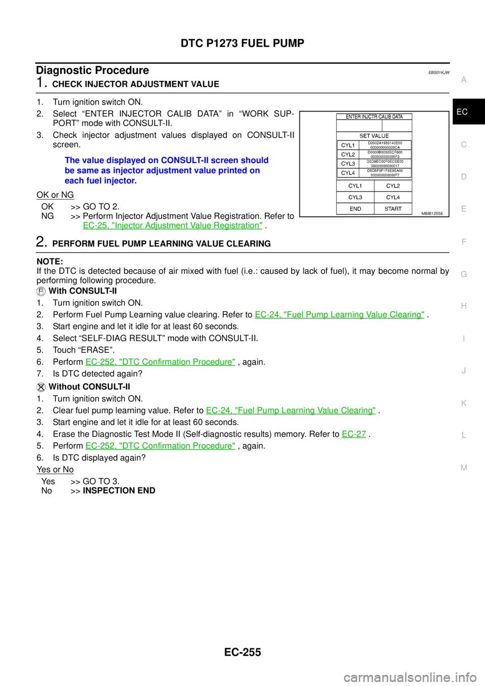
1.CHECK INJECTOR ADJUSTMENT VALUE
1. Turn ignition switch ON.
2. Select “ENTER INJECTOR CALIB DATA” in “WORK SUP-
PORT” mode with CONSULT-II.
3. Check injector adjustment values displayed on CONSULT-II
screen.
OK or NG
OK >> GO TO 2.
NG >> Perform Injector Adjustment Value Registration. Refer to
EC-25, "
Injector Adjustment Value Registration".
2.PERFORM FUEL PUMP LEARNING VALUE CLEARING
NOTE:
If the DTC is detected because of air mixed with fuel (i.e.: caused by lack of fuel), it may become normal by
performing following procedure.
With CONSULT-II
1. Turn ignition switch ON.
2. Perform Fuel Pump Learning value clearing. Refer toEC-24, "
Fuel Pump Learning Value Clearing".
3. Start engine and let it idle for at least 60 seconds.
4. Select “SELF-DIAG RESULT” mode with CONSULT-II.
5. Touch “ERASE”.
6. PerformEC-252, "
DTC Confirmation Procedure", again.
7. Is DTC detected again?
Without CONSULT-II
1. Turn ignition switch ON.
2. Clear fuel pump learning value. Refer toEC-24, "
Fuel Pump Learning Value Clearing".
3. Start engine and let it idle for at least 60 seconds.
4. Erase the Diagnostic Test Mode II (Self-diagnostic results) memory. Refer toEC-27
.
5. PerformEC-252, "
DTC Confirmation Procedure", again.
6. Is DTC displayed again?
Ye s o r N o
Ye s > > G O T O 3 .
No >>INSPECTION END The value displayed on CONSULT-II screen should
be same as injector adjustment value printed on
each fuel injector.
MBIB1255E
Page 1239 of 3171
DTC P1274 FUEL PUMP
EC-259
C
D
E
F
G
H
I
J
K
L
MA
EC
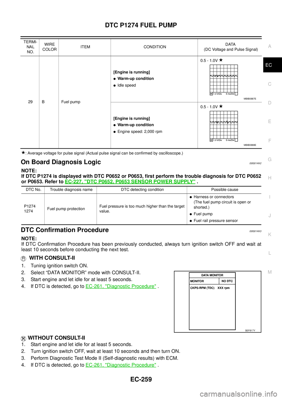
: Average voltage for pulse signal (Actual pulse signal can be confirmed by oscilloscope.)
On Board Diagnosis LogicEBS01KK2
NOTE:
If DTC P1274 is displayed with DTC P0652 or P0653, first perform the trouble diagnosis for DTC P0652
or P0653. Refer toEC-227, "
DTC P0652, P0653 SENSOR POWER SUPPLY".
DTC Confirmation ProcedureEBS01KK3
NOTE:
If DTC Confirmation Procedure has been previously conducted, always turn ignition switch OFF and wait at
least 10 seconds before conducting the next test.
WITH CONSULT-II
1. Tuning ignition switch ON.
2. Select “DATA MONITOR” mode with CONSULT-II.
3. Start engine and let idle for at least 5 seconds.
4. If DTC is detected, go toEC-261, "
Diagnostic Procedure".
WITHOUT CONSULT-II
1. Start engine and let idle for at least 5 seconds.
2. Turn ignition switch OFF, wait at least 10 seconds and then turn ON.
3. Perform Diagnostic Test Mode II (Self-diagnostic results) with ECM.
4. If DTC is detected, go toEC-261, "
Diagnostic Procedure".
29 B Fuel pump[Engine is running]
lWarm-up condition
lIdle speed0.5 - 1.0V
[Engine is running]
lWarm-up condition
lEngine speed: 2,000 rpm0.5 - 1.0V TERMI-
NAL
NO.WIRE
COLORITEM CONDITIONDATA
(DC Voltage and Pulse Signal)
MBIB0887E
MBIB0888E
DTC No. Trouble diagnosis name DTC detecting condition Possible cause
P1274
1274Fuel pump protectionFuel pressure is too much higher than the target
value.
lHarness or connectors
(The fuel pump circuit is open or
shorted.)
lFuel pump
lFuel rail pressure sensor
SEF817Y
Page 1244 of 3171
EC-264
DTC P1275 FUEL PUMP
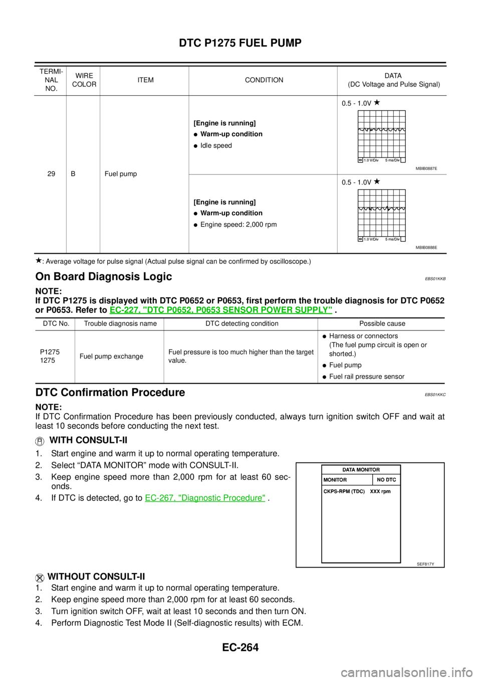
: Average voltage for pulse signal (Actual pulse signal can be confirmed by oscilloscope.)
On Board Diagnosis LogicEBS01KKB
NOTE:
If DTC P1275 is displayed with DTC P0652 or P0653, first perform the trouble diagnosis for DTC P0652
or P0653. Refer toEC-227, "
DTC P0652, P0653 SENSOR POWER SUPPLY".
DTC Confirmation ProcedureEBS01KKC
NOTE:
If DTC Confirmation Procedure has been previously conducted, always turn ignition switch OFF and wait at
least 10 seconds before conducting the next test.
WITH CONSULT-II
1. Start engine and warm it up to normal operating temperature.
2. Select “DATA MONITOR” mode with CONSULT-II.
3. Keep engine speed more than 2,000 rpm for at least 60 sec-
onds.
4. If DTC is detected, go toEC-267, "
Diagnostic Procedure".
WITHOUT CONSULT-II
1. Start engine and warm it up to normal operating temperature.
2. Keep engine speed more than 2,000 rpm for at least 60 seconds.
3. Turn ignition switch OFF, wait at least 10 seconds and then turn ON.
4. Perform Diagnostic Test Mode II (Self-diagnostic results) with ECM.
29 B Fuel pump[Engine is running]
lWarm-up condition
lIdle speed0.5 - 1.0V
[Engine is running]
lWarm-up condition
lEngine speed: 2,000 rpm0.5 - 1.0V TERMI-
NAL
NO.WIRE
COLORITEM CONDITIONDATA
(DC Voltage and Pulse Signal)
MBIB0887E
MBIB0888E
DTC No. Trouble diagnosis name DTC detecting condition Possible cause
P1275
1275Fuel pump exchangeFuel pressure is too much higher than the target
value.
lHarness or connectors
(The fuel pump circuit is open or
shorted.)
lFuel pump
lFuel rail pressure sensor
SEF817Y
Page 1249 of 3171
DTC P1616 ECM
EC-269
C
D
E
F
G
H
I
J
K
L
MA
EC
DTC P1616 ECMPFP:23710
DescriptionEBS01KKH
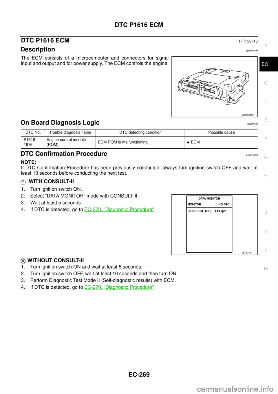
The ECM consists of a microcomputer and connectors for signal
input and output and for power supply. The ECM controls the engine.
On Board Diagnosis LogicEBS01KKI
DTC Confirmation ProcedureEBS01KKJ
NOTE:
If DTC Confirmation Procedure has been previously conducted, always turn ignition switch OFF and wait at
least 10 seconds before conducting the next test.
WITH CONSULT-II
1. Turn ignition switch ON.
2. Select “DATA MONITOR” mode with CONSULT-II.
3. Wait at least 5 seconds.
4. If DTC is detected, go toEC-270, "
Diagnostic Procedure".
WITHOUT CONSULT-II
1. Turn ignition switch ON and wait at least 5 seconds.
2. Turn ignition switch OFF, wait at least 10 seconds and then turn ON.
3. Perform Diagnostic Test Mode II (Self-diagnostic results) with ECM.
4. If DTC is detected, go toEC-270, "
Diagnostic Procedure".
MBIB0625E
DTC No. Trouble diagnosis name DTC detecting condition Possible cause
P1616
1616Engine control module
(ROM)ECM ROM is malfunctioning.
lECM
SEF817Y
Page 1251 of 3171
DTC P1622 INJECTOR ADJUSTMENT VALUE
EC-271
C
D
E
F
G
H
I
J
K
L
MA
EC
DTC P1622 INJECTOR ADJUSTMENT VALUEPFP:23710
DescriptionEBS01KKL
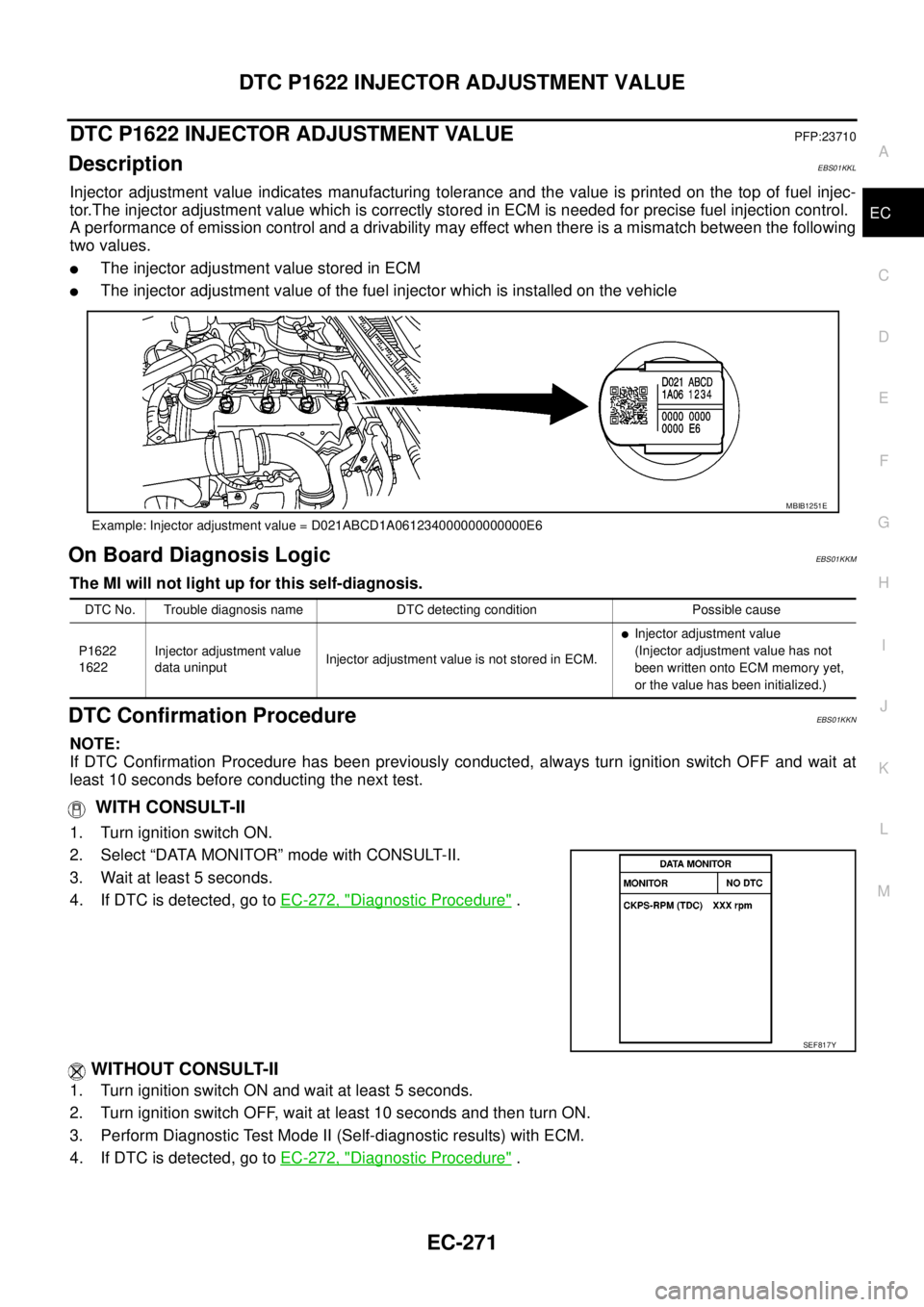
Injector adjustment value indicates manufacturing tolerance and the value is printed on the top of fuel injec-
tor.The injector adjustment value which is correctly stored in ECM is needed for precise fuel injection control.
A performance of emission control and a drivability may effect when there is a mismatch between the following
two values.
lThe injector adjustment value stored in ECM
lThe injector adjustment value of the fuel injector which is installed on the vehicle
On Board Diagnosis LogicEBS01KKM
The MI will not light up for this self-diagnosis.
DTC Confirmation ProcedureEBS01KKN
NOTE:
If DTC Confirmation Procedure has been previously conducted, always turn ignition switch OFF and wait at
least 10 seconds before conducting the next test.
WITH CONSULT-II
1. Turn ignition switch ON.
2. Select “DATA MONITOR” mode with CONSULT-II.
3. Wait at least 5 seconds.
4. If DTC is detected, go toEC-272, "
Diagnostic Procedure".
WITHOUT CONSULT-II
1. Turn ignition switch ON and wait at least 5 seconds.
2. Turn ignition switch OFF, wait at least 10 seconds and then turn ON.
3. Perform Diagnostic Test Mode II (Self-diagnostic results) with ECM.
4. If DTC is detected, go toEC-272, "
Diagnostic Procedure".
Example: Injector adjustment value = D021ABCD1A061234000000000000E6
MBIB1251E
DTC No. Trouble diagnosis name DTC detecting condition Possible cause
P1622
1622Injector adjustment value
data uninputInjector adjustment value is not stored in ECM.
lInjector adjustment value
(Injector adjustment value has not
been written onto ECM memory yet,
or the value has been initialized.)
SEF817Y
Page 1253 of 3171
DTC P1623 INJECTOR ADJUSTMENT VALUE
EC-273
C
D
E
F
G
H
I
J
K
L
MA
EC
DTC P1623 INJECTOR ADJUSTMENT VALUEPFP:23710
DescriptionEBS01KKP
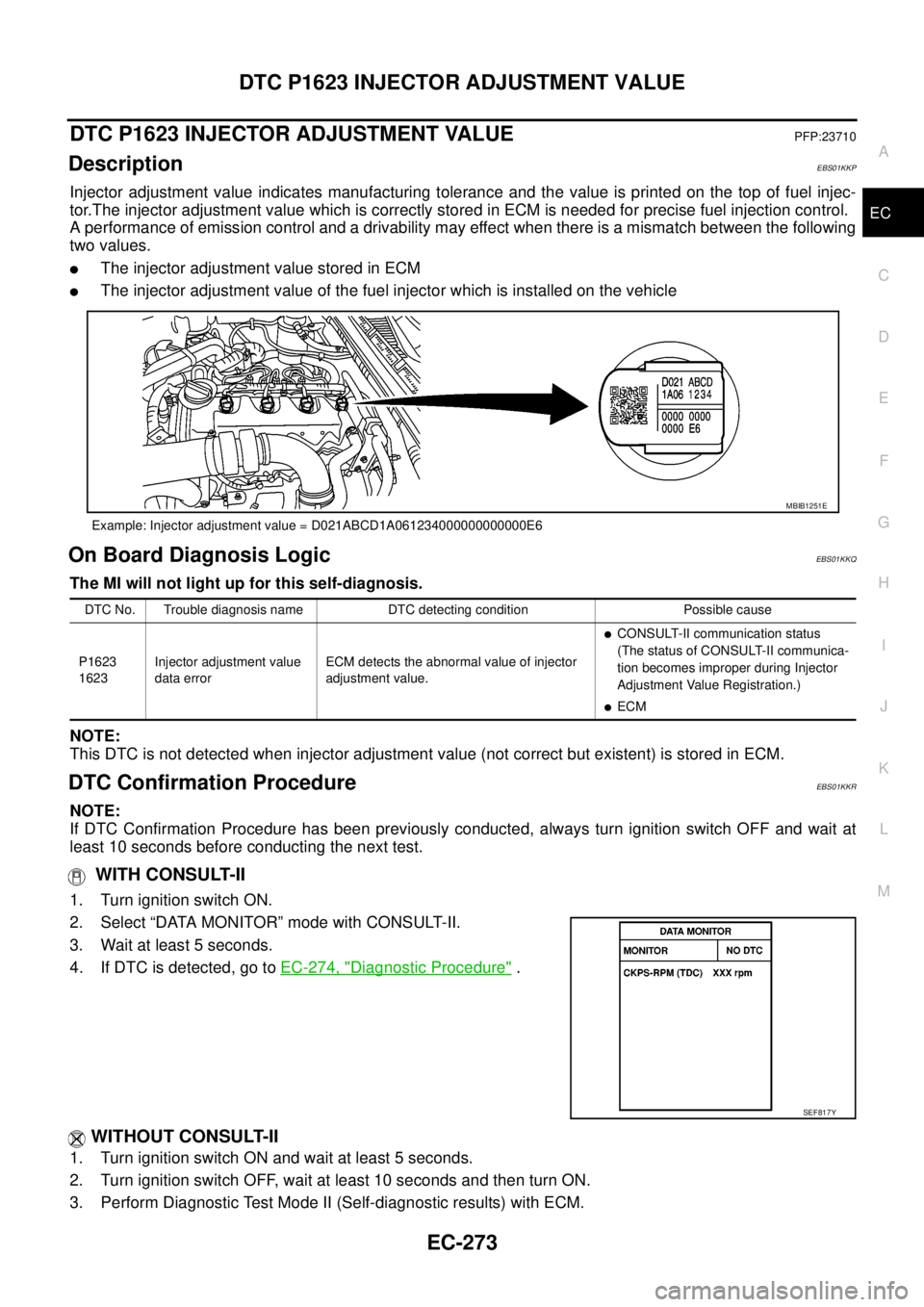
Injector adjustment value indicates manufacturing tolerance and the value is printed on the top of fuel injec-
tor.The injector adjustment value which is correctly stored in ECM is needed for precise fuel injection control.
A performance of emission control and a drivability may effect when there is a mismatch between the following
two values.
lThe injector adjustment value stored in ECM
lThe injector adjustment value of the fuel injector which is installed on the vehicle
On Board Diagnosis LogicEBS01KKQ
The MI will not light up for this self-diagnosis.
NOTE:
This DTC is not detected when injector adjustment value (not correct but existent) is stored in ECM.
DTC Confirmation ProcedureEBS01KKR
NOTE:
If DTC Confirmation Procedure has been previously conducted, always turn ignition switch OFF and wait at
least 10 seconds before conducting the next test.
WITH CONSULT-II
1. Turn ignition switch ON.
2. Select “DATA MONITOR” mode with CONSULT-II.
3. Wait at least 5 seconds.
4. If DTC is detected, go toEC-274, "
Diagnostic Procedure".
WITHOUT CONSULT-II
1. Turn ignition switch ON and wait at least 5 seconds.
2. Turn ignition switch OFF, wait at least 10 seconds and then turn ON.
3. Perform Diagnostic Test Mode II (Self-diagnostic results) with ECM.
Example: Injector adjustment value = D021ABCD1A061234000000000000E6
MBIB1251E
DTC No. Trouble diagnosis name DTC detecting condition Possible cause
P1623
1623Injector adjustment value
data errorECM detects the abnormal value of injector
adjustment value.
lCONSULT-II communication status
(The status of CONSULT-II communica-
tion becomes improper during Injector
Adjustment Value Registration.)
lECM
SEF817Y