2005 NISSAN NAVARA ECO mode
[x] Cancel search: ECO modePage 2130 of 3171
HEADLAMP - DAYTIME LIGHT SYSTEM -
LT-47
C
D
E
F
G
H
I
J
L
MA
B
LT
Daytime Light Control Does Not Operate Properly (Normal Headlamps Operate
Properly)
EKS00Q7Q
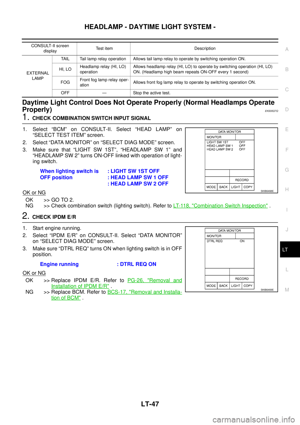
1.CHECK COMBINATION SWITCH INPUT SIGNAL
1. Select “BCM” on CONSULT-II. Select “HEAD LAMP” on
“SELECT TEST ITEM” screen.
2. Select “DATA MONITOR” on “SELECT DIAG MODE” screen.
3. Make sure that “LIGHT SW 1ST”, “HEADLAMP SW 1” and
“HEADLAMP SW 2” turns ON-OFF linked with operation of light-
ing switch.
OK or NG
OK >> GO TO 2.
NG >> Check combination switch (lighting switch). Refer toLT- 11 8 , "
Combination Switch Inspection".
2.CHECK IPDM E/R
1. Start engine running.
2. Select “IPDM E/R” on CONSULT-II. Select “DATA MONITOR”
on “SELECT DIAG MODE” screen.
3. Make sure “DTRL REQ” turns ON when lighting switch is in OFF
position.
OK or NG
OK >> Replace IPDM E/R. Refer toPG-26, "Removal and
Installation of IPDM E/R".
NG >> Replace BCM. Refer toBCS-17, "
Removal and Installa-
tion of BCM".
CONSULT-II screen
displayTest item Description
EXTERNAL
LAMPTAIL Tail lamp relay operation Allows tail lamp relay to operate by switching operation ON.
HI, LOHeadlamp relay (HI, LO)
operationAllows headlamp relay (HI, LO) to operate by switching operation (HI, LO)
ON. (Headlamp high beam repeats ON-OFF every 1 second)
FOGFront fog lamp relay oper-
ationAllows front fog lamp relay to operate by switching operation ON.
OFF — Stoptheactivetest.
When lighting switch is
OFF position:LIGHTSW1STOFF
: HEAD LAMP SW 1 OFF
: HEAD LAMP SW 2 OFF
SKIB6468E
Engine running : DTRL REQ ON
SKIB6469E
Page 2143 of 3171
LT-60
AUTO LIGHT SYSTEM
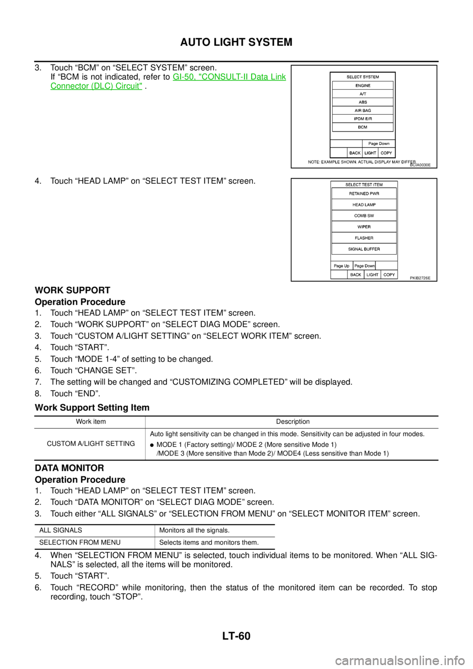
3. Touch “BCM” on “SELECT SYSTEM” screen.
If “BCM is not indicated, refer toGI-50, "
CONSULT-II Data Link
Connector (DLC) Circuit".
4. Touch “HEAD LAMP” on “SELECT TEST ITEM” screen.
WORK SUPPORT
Operation Procedure
1. Touch “HEAD LAMP” on “SELECT TEST ITEM” screen.
2. Touch “WORK SUPPORT” on “SELECT DIAG MODE” screen.
3. Touch “CUSTOM A/LIGHT SETTING” on “SELECT WORK ITEM” screen.
4. Touch “START”.
5. Touch “MODE 1-4” of setting to be changed.
6. Touch “CHANGE SET”.
7. The setting will be changed and “CUSTOMIZING COMPLETED” will be displayed.
8. Touch “END”.
Work Support Setting Item
DATA MONITOR
Operation Procedure
1. Touch “HEAD LAMP” on “SELECT TEST ITEM” screen.
2. Touch “DATA MONITOR” on “SELECT DIAG MODE” screen.
3. Touch either “ALL SIGNALS” or “SELECTION FROM MENU” on “SELECT MONITOR ITEM” screen.
4. When “SELECTION FROM MENU” is selected, touch individual items to be monitored. When “ALL SIG-
NALS” is selected, all the items will be monitored.
5. Touch “START”.
6. Touch “RECORD” while monitoring, then the status of the monitored item can be recorded. To stop
recording, touch “STOP”.
BCIA0030E
PKIB2726E
Work item Description
CUSTOM A/LIGHT SETTINGAuto light sensitivity can be changed in this mode. Sensitivity can be adjusted in four modes.
lMODE 1 (Factory setting)/ MODE 2 (More sensitive Mode 1)
/MODE 3 (More sensitive than Mode 2)/ MODE4 (Less sensitive than Mode 1)
ALL SIGNALS Monitors all the signals.
SELECTION FROM MENU Selects items and monitors them.
Page 2145 of 3171
LT-62
AUTO LIGHT SYSTEM
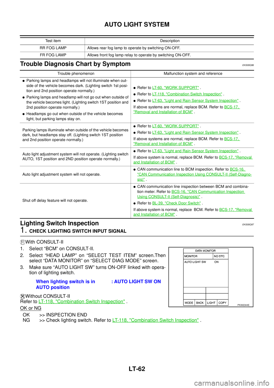
Trouble Diagnosis Chart by Symptom
EKS00Q86
Lighting Switch InspectionEKS00Q87
1.CHECK LIGHTING SWITCH INPUT SIGNAL
With CONSULT-II
1. Select “BCM” on CONSULT-II.
2. Select “HEAD LAMP” on “SELECT TEST ITEM” screen.Then
select “DATA MONITOR” on “SELECT DIAG MODE” screen.
3. Make sure “AUTO LIGHT SW” turns ON-OFF linked with opera-
tion of lighting switch.
Without CONSULT-II
Refer toLT- 11 8 , "
Combination Switch Inspection".
OK or NG
OK >> INSPECTION END
NG >> Check lighting switch. Refer toLT- 11 8 , "
Combination Switch Inspection".
RR FOG LAMP Allows rear fog lamp to operate by switching ON-OFF.
FR FOG LAMP Allows front fog lamp relay to operate by switching ON-OFF.Test item Description
Trouble phenomenon Malfunction system and reference
lParking lamps and headlamps will not illuminate when out-
side of the vehicle becomes dark. (Lighting switch 1st posi-
tion and 2nd position operate normally.)
lParking lamps and headlamp will not go out when outside of
the vehicle becomes light. (Lighting switch 1ST position and
2nd position operate normally.)
lHeadlamps go out when outside of the vehicle becomes
light, but parking lamps stay on.
lRefer toLT- 6 0 , "WORK SUPPORT".
lRefer toLT- 11 8 , "Combination Switch Inspection".
lRefer toLT- 6 3 , "Light and Rain Sensor System Inspection".
If above systems are normal, replace BCM. Refer toBCS-17,
"Removal and Installation of BCM".
Parking lamps illuminate when outside of the vehicle becomes
dark, but headlamps stay off. (Lighting switch 1ST position
and 2nd position operate normally.)
lRefer toLT- 6 0 , "WORK SUPPORT".
lRefer toLT- 6 3 , "Light and Rain Sensor System Inspection".
If above systems are normal, replace BCM. Refer toBCS-17,
"Removal and Installation of BCM".
Auto light adjustment system will not operate. (Lighting switch
AUTO, 1ST position and 2ND position operate normally.)
lRefer toLT- 6 3 , "Light and Rain Sensor System Inspection".
If above system is normal, replace BCM. Refer toBCS-17, "
Removal
and Installation of BCM".
Auto light adjustment system will not operate.
lCAN communication line to BCM inspection. Refer toBCS-16,
"CAN Communication Inspection Using CONSULT-II (Self-Diagno-
sis)".
Shut off delay feature will not operate.
lCAN communication line inspection between BCM and combina-
tion meter. Refer toBCS-16, "
CAN Communication Inspection
Using CONSULT-II (Self-Diagnosis)".
lRefer toBL-39, "Check Door Switch".
If above system is normal, replace BCM. Refer toBCS-17, "
Removal
and Installation of BCM".
When lighting switch is in
AUTO position: AUTO LIGHT SW ON
PKIA6344E
Page 2178 of 3171
REAR FOG LAMP
LT-95
C
D
E
F
G
H
I
J
L
MA
B
LT
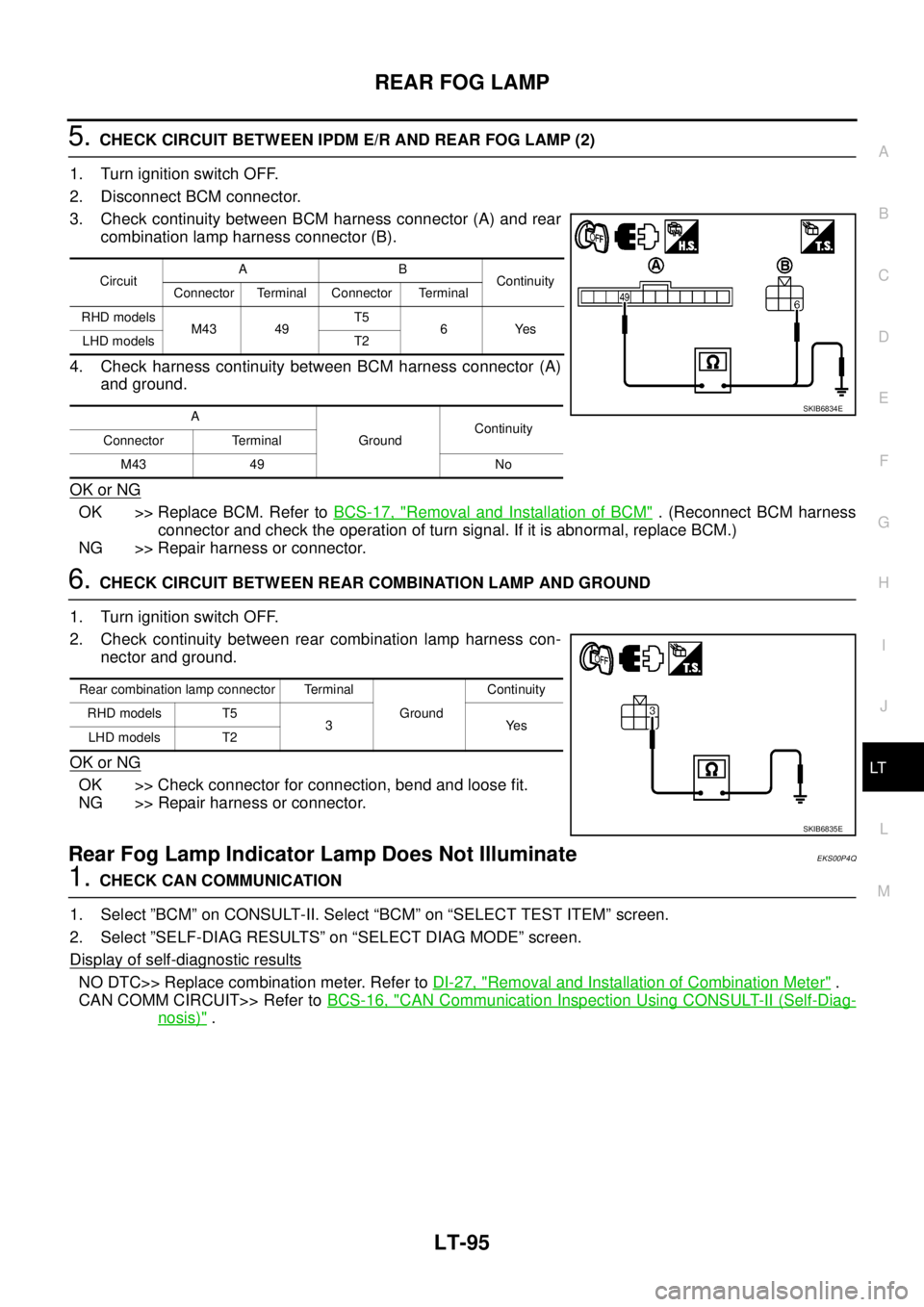
5.CHECK CIRCUIT BETWEEN IPDM E/R AND REAR FOG LAMP (2)
1. Turn ignition switch OFF.
2. Disconnect BCM connector.
3. Check continuity between BCM harness connector (A) and rear
combination lamp harness connector (B).
4. Check harness continuity between BCM harness connector (A)
and ground.
OK or NG
OK >> Replace BCM. Refer toBCS-17, "Removal and Installation of BCM". (Reconnect BCM harness
connector and check the operation of turn signal. If it is abnormal, replace BCM.)
NG >> Repair harness or connector.
6.CHECK CIRCUIT BETWEEN REAR COMBINATION LAMP AND GROUND
1. Turn ignition switch OFF.
2. Check continuity between rear combination lamp harness con-
nector and ground.
OK or NG
OK >> Check connector for connection, bend and loose fit.
NG >> Repair harness or connector.
Rear Fog Lamp Indicator Lamp Does Not IlluminateEKS00P4Q
1.CHECK CAN COMMUNICATION
1. Select ”BCM” on CONSULT-II. Select “BCM” on “SELECT TEST ITEM” screen.
2. Select ”SELF-DIAG RESULTS” on “SELECT DIAG MODE” screen.
Display of self
-diagnostic results
NO DTC>> Replace combination meter. Refer toDI-27, "Removal and Installation of Combination Meter".
CAN COMM CIRCUIT>> Refer toBCS-16, "
CAN Communication Inspection Using CONSULT-II (Self-Diag-
nosis)".
CircuitAB
Continuity
Connector Terminal Connector Terminal
RHD models
M43 49T5
6Yes
LHD models T2
A
GroundContinuity
Connector Terminal
M43 49 No
SKIB6834E
Rear combination lamp connector Terminal
GroundContinuity
RHD models T5
3Yes
LHD models T2
SKIB6835E
Page 2189 of 3171

LT-106
TURN SIGNAL AND HAZARD WARNING LAMPS
4. Touch “FLASHER” on “SELECT TEST ITEM” screen.
DATA MONITOR
Operation Procedure
1. Touch “FLASHER” on “SELECT TEST ITEM” screen.
2. Touch “DATA MONITOR” on “SELECT DIAG MODE” screen.
3. Touch either “ALL SIGNALS” or “SELECTION FROM MENU” on “SELECT MONITOR ITEM” screen.
4. When “SELECTION FROM MENU” is selected, touch items to be monitored. When “ALL SIGNALS” is
selected, all the items will be monitored.
5. Touch “START”.
6. Touch “RECORD” while monitoring, then the status of the monitored item can be recorded. To stop
recording, touch “STOP”.
Display Item List
ACTIVE TEST
Operation Procedure
1. Touch “FLASHER” on “SELECT TEST ITEM” screen.
2. Touch “ACTIVE TEST” on “SELECT DIAG MODE” screen.
3. Touch item to be tested and check operation of the selected item.
4. During the operation check, touching “OFF” deactivates the operation.
Display Item List
PKIC0325E
ALL SIGNALS Monitors all the signals.
SELECTION FROM MENU Selects items and monitors them.
Monitor item Contents
IGN ON SW “ON/OFF”Displays status (ignition switch IGN position: ON/other: OFF) of ignition switch judged from the
ignition switch signal.
HAZARD SW “ON/OFF”Displays status (hazard switch ON position: ON/other: OFF) of hazard switch judged from the
hazard switch signal.
TURN SIGNAL R “ON/OFF”Displays status (turn signal switch right position: ON/other: OFF) of turn RH switch judged from
the turn signal switch signal.
TURN SIGNAL L “ON/OFF”Displays status (turn signal switch left position: ON/other: OFF) of turn LH switch judged from
the turn signal switch signal.
BRAKE SW “ON/OFF” Displays status of stop lamp switch.
Test item Description
FLASHER (RH) Turn signal lamp (right) can be operated by any ON-OFF operations.
FLASHER (LH) Turn signal lamp (left) can be operated by any ON-OFF operations.
Page 2199 of 3171

LT-116
COMBINATION SWITCH
4. Touch “COMB SW” on “SELECT TEST ITEM” screen.
DATA MONITOR
Operation Procedure
1. Touch “COMB SW” on “SELECT TEST ITEM” screen.
2. Touch “DATA MONITOR” on “SELECT DIAG MODE” screen.
3. Touch either “ALL SIGNALS” or “SELECTION FROM MENU” on “SELECT MONITOR ITEM” screen.
4. When “ALL SIGNALS” is selected, all the signals will be monitored. When “SELECTION FROM MENU” is
selected, touch items to be monitored.
5. Touch “START”.
6. Touch “RECORD” while monitoring, then the status of the monitored item can be recorded. To stop
recording, touch “STOP”.
Display Item List
PKIB6096E
ALL SIGNALS Monitors all the signals.
SELECTION FROM MENU Selects and monitors individual signal.
Monitor item Contents
TURN SIGNAL R “ON/OFF”Displays status (turn signal switch right position: ON/other: OFF) of turn RH switch judged from the
turn signal switch signal.
TURN SIGNAL L “ON/OFF”Displays status (turn signal switch left position: ON/other: OFF) of turn LH switch judged from the
turn signal switch signal.
HI BEAM SW “ON/OFF”Displays status (lighting switch high beam position: ON/other: OFF) of high beam switch judged
from the lighting switch signal.
HEAD LAMP SW 1 “ON/OFF”Displays status (lighting switch 2ND position: ON/other: OFF) of headlamp 1 switch judged from
the lighting switch signal.
HEAD LAMP SW 2 “ON/OFF”Displays status (lighting switch 2ND position: ON/other: OFF) of headlamp 2 switch judged from
the lighting switch signal.
LIGHT SW 1ST “ON/OFF”Displays status (lighting switch 1ST or 2ND position: ON/other: OFF) of lighting switch 1ST position
switch judged from the lighting switch signal.
PASSING SW “ON/OFF”Displays status (lighting switch passing position: ON/other: OFF) of passing switch judged from the
lighting switch signal.
FR FOG SW “ON/OFF”Displays status (lighting switch front fog lamp ON position: ON/others: OFF) of front fog lamp
switch judged from the lighting switch signal.
RR FOG SW “ON/OFF”Displays status (rear fog lamp switch position: ON/other: OFF) of rear fog switch judged from the
lighting switch signal.
FR WIPER HI “ON/OFF”Displays status (front wiper switch high position: ON/other: OFF) of front wiper high switch judged
from the wiper switch signal.
FR WIPER LOW “ON/OFF”Displays status (front wiper switch low position: ON/other: OFF) of front wiper low switch judged
from the wiper switch signal.
FR WIPER INT “ON/OFF”Displays status (front wiper switch intermittent position: ON/other: OFF) of front wiper intermittent
switch judged from the wiper switch signal.
FR WASHER SW “ON/OFF”Displays status (front washer switch ON position: ON/other: OFF) of front washer switch judged
from the wiper switch signal.
Page 2228 of 3171
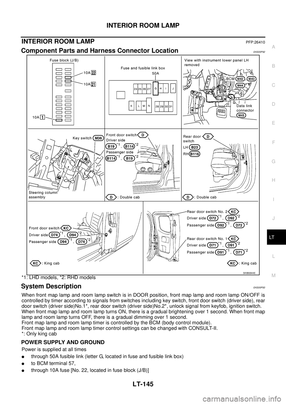
INTERIOR ROOM LAMP
LT-145
C
D
E
F
G
H
I
J
L
MA
B
LT
INTERIOR ROOM LAMPPFP:26410
Component Parts and Harness Connector LocationEKS00P92
*1: LHD models, *2: RHD models
System DescriptionEKS00P93
When front map lamp and room lamp switch is in DOOR position, front map lamp and room lamp ON/OFF is
controlled by timer according to signals from switches including key switch, front door switch (driver side), rear
door switch (driver side)No.1*, rear door switch (driver side)No.2*, unlock signal from keyfob, ignition switch.
When front map lamp and room lamp turns ON, there is a gradual brightening over 1 second. When front map
lamp and room lamp turns OFF, there is a gradual dimming over 1 second.
Front map lamp and room lamp timer is controlled by the BCM (body control module).
Front map lamp and room lamp timer control settings can be changed with CONSULT-II.
*: Only king cab
POWER SUPPLY AND GROUND
Power is supplied at all times
lthrough 50A fusible link (letter G, located in fuse and fusible link box)
lto BCM terminal 57,
lthrough 10A fuse [No. 22, located in fuse block (J/B)]
SKIB6844E
Page 2230 of 3171

INTERIOR ROOM LAMP
LT-147
C
D
E
F
G
H
I
J
L
MA
B
LT
lthrough rear door switch (passenger side) No.1 and No.2 terminals 2
lthrough grounds B9 and B25 (LHD models)
lthrough grounds B106 and B121 (RHD models).
When a signal is received by BCM, power is supplied
lthrough BCM terminal 42
lto key ring lamp terminal 1
lto front map lamp terminal 1 and
lto room lamp terminal 2.
SWITCH OPERATION
When front map lamp switch is ON, ground is supplied
lto front map lamp terminal 2
lthrough grounds M21, M80 and M83.
When room lamp switch is ON, ground is supplied through room lamp case ground.
ROOM LAMP TIMER OPERATION
When lamp switch is in DOOR position, and when all conditions below are met, BCM performs timer control
(maximum 30 seconds) for interior room lamp and map lamp ON/OFF.
Power is supplied
lthrough 10A fuse [No. 22, located in fuse block (J/B)]
lto key switch terminal 2.
Key is removed from ignition key cylinder (key switch OFF), power will not be supplied to BCM terminal 5.
At the time that driver's door is opened, BCM detects that driver's door is unlocked. It determines that room
lamp timer operation conditions are met, and turns the interior room lamps ON for 30 seconds.
Key is in ignition key cylinder (key switch ON), power is supplied
lthrough key switch terminal 1
lto BCM terminal 5.
When key is removed from key switch (key switch OFF), power supply to BCM terminal 5 is terminated. BCM
detects that key has been removed, determines that room lamp timer conditions are met, and turns the interior
room lamps ON for 30 seconds.
When driver's door opens®closes, and the key is not inserted in the key switch (key switch OFF), BCM ter-
minal 15 changes between 0V (door open)®12V (door closed). The BCM determines that conditions for
room lamp operation are met and turns the room lamp ON for 30 seconds.
Timer control is canceled under the following conditions.
lDriver's door is opened [front door switch (driver side)].
lIgnition switch ON.
lKeyfob
INTERIOR LAMP BATTERY SAVER CONTROL
If interior lamp is left ON, it will not be turned off even when door is closed.
BCM turns off interior lamp automatically to save battery 30 minutes after ignition switch is turned off.
BCM controls interior lamps listed below:
lFront map lamp
lRoom lamp
lKey ring lamp
After lamps turn OFF by the battery saver system, the lamps illuminate again when
lsignal received from keyfob or key cylinder is locked or unlocked,
ldoor is opened or closed,
lkey is removed from ignition key cylinder or inserted in ignition key cylinder.
Interior lamp battery saver control period can be changed by the function setting of CONSULT-II. Refer toLT-
158, "WORK SUPPORT".