Page 1256 of 3171

EC-276
DTC P2135 APP SENSOR
On Board Diagnosis Logic
EBS01KKW
The MI will not light up for this self-diagnosis.
NOTE:
lIf DTC P2135 is displayed with DTC P0642 or P0643, first perform the trouble diagnosis for DTC
P0642 or P0643. Refer toEC-222, "
DTC P0642, P0643 SENSOR POWER SUPPLY".
lIf DTC P2135 is displayed with DTC P0652 or P0653, first perform the trouble diagnosis for DTC
P0652 or P0653. Refer toEC-227, "
DTC P0652, P0653 SENSOR POWER SUPPLY".
DTC Confirmation ProcedureEBS01KKX
NOTE:
If DTC Confirmation Procedure has been previously conducted, always turn ignition switch OFF and wait at
least 10 seconds before conducting the next test.
WITH CONSULT-II
1. Turn ignition switch ON.
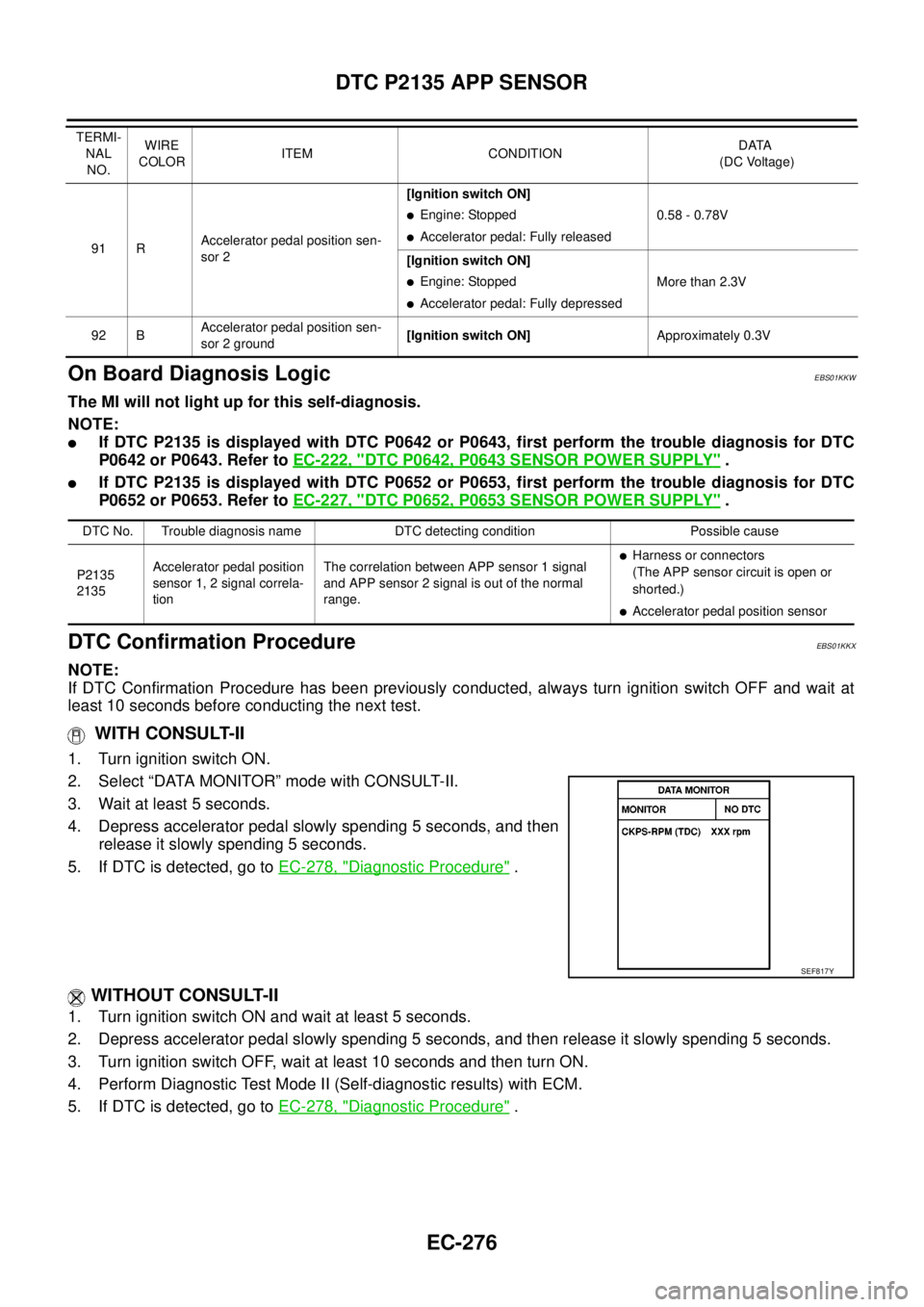
2. Select “DATA MONITOR” mode with CONSULT-II.
3. Wait at least 5 seconds.
4. Depress accelerator pedal slowly spending 5 seconds, and then
release it slowly spending 5 seconds.
5. If DTC is detected, go toEC-278, "
Diagnostic Procedure".
WITHOUT CONSULT-II
1. Turn ignition switch ON and wait at least 5 seconds.
2. Depress accelerator pedal slowly spending 5 seconds, and then release it slowly spending 5 seconds.
3. Turn ignition switch OFF, wait at least 10 seconds and then turn ON.
4. Perform Diagnostic Test Mode II (Self-diagnostic results) with ECM.
5. If DTC is detected, go toEC-278, "
Diagnostic Procedure".
91 RAccelerator pedal position sen-
sor 2[Ignition switch ON]
lEngine: Stopped
lAccelerator pedal: Fully released0.58 - 0.78V
[Ignition switch ON]
lEngine: Stopped
lAccelerator pedal: Fully depressedMore than 2.3V
92 BAccelerator pedal position sen-
sor 2 ground[Ignition switch ON]Approximately 0.3V TERMI-
NAL
NO.WIRE
COLORITEM CONDITIONDATA
(DC Voltage)
DTC No. Trouble diagnosis name DTC detecting condition Possible cause
P2135
2135Accelerator pedal position
sensor 1, 2 signal correla-
tionThe correlation between APP sensor 1 signal
and APP sensor 2 signal is out of the normal
range.
lHarness or connectors
(The APP sensor circuit is open or
shorted.)
lAccelerator pedal position sensor
SEF817Y
Page 1263 of 3171
DTC P2146, P2149 FUEL INJECTOR POWER SUPPLY
EC-283
C
D
E
F
G
H
I
J
K
L
MA
EC
DTC Confirmation ProcedureEBS01KL6
NOTE:
If DTC Confirmation Procedure has been previously conducted, always turn ignition switch OFF and wait at
least 10 seconds before conducting the next test.
TESTING CONDITION
Before performing the following procedure, confirm the ambient temperature is more than -20°C (-4°F).
WITH CONSULT-II
1. Turn ignition switch ON.
2. Select “DATA MONITOR” mode with CONSULT-II.
3. Start engine and let it idle for at least 5 seconds.
4. If DTC is detected, go toEC-285, "
Diagnostic Procedure".
WITHOUT CONSULT-II
1. Start engine and let it idle for at least 5 seconds.
2. Turn ignition switch OFF, wait at least 10 seconds and then turn ON.
3. Perform Diagnostic Test Mode II (Self-diagnostic results) with ECM.
4. If DTC is detected, go toEC-285, "
Diagnostic Procedure".
SEF817Y
Page 1268 of 3171
EC-288
DTC P2147, P2148 FUEL INJECTOR CIRCUIT
DTC Confirmation Procedure
EBS01KLD
NOTE:
If DTC Confirmation Procedure has been previously conducted, always turn ignition switch OFF and wait at
least 10 seconds before conducting the next test.
WITH CONSULT-II
1. Turn ignition switch ON.
2. Select “DATA MONITOR” mode with CONSULT-II.
3. Start engine and let it idle for at least 5 seconds.
4. If DTC is detected, go toEC-290, "
Diagnostic Procedure".
WITHOUT CONSULT-II
1. Start engine and let it idle for at least 5 seconds.
2. Turn ignition switch OFF, wait at least 10 seconds and then turn ON.
3. Perform Diagnostic Test Mode II (Self-diagnostic results) with ECM.
4. If DTC is detected, go toEC-290, "
Diagnostic Procedure".
SEF817Y
Page 1273 of 3171

DTC P2228, P2229 BARO SENSOR
EC-293
C
D
E
F
G
H
I
J
K
L
MA
EC
DTC P2228, P2229 BARO SENSORPFP:23731
DescriptionEBS01KLI
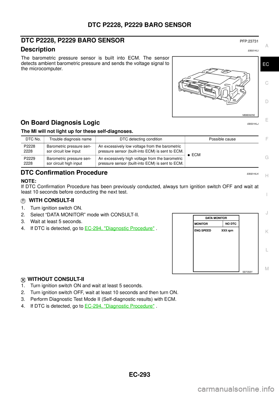
The barometric pressure sensor is built into ECM. The sensor
detects ambient barometric pressure and sends the voltage signal to
the microcomputer.
On Board Diagnosis LogicEBS01KLJ
The MI will not light up for these self-diagnoses.
DTC Confirmation ProcedureEBS01KLK
NOTE:
If DTC Confirmation Procedure has been previously conducted, always turn ignition switch OFF and wait at
least 10 seconds before conducting the next test.
WITH CONSULT-II
1. Turn ignition switch ON.
2. Select “DATA MONITOR” mode with CONSULT-II.
3. Wait at least 5 seconds.
4. If DTC is detected, go toEC-294, "
Diagnostic Procedure".
WITHOUT CONSULT-II
1. Turn ignition switch ON and wait at least 5 seconds.
2. Turn ignition switch OFF, wait at least 10 seconds and then turn ON.
3. Perform Diagnostic Test Mode II (Self-diagnostic results) with ECM.
4. If DTC is detected, go toEC-294, "
Diagnostic Procedure".
MBIB0625E
DTC No. Trouble diagnosis name DTC detecting condition Possible cause
P2228
2228Barometric pressure sen-
sor circuit low inputAn excessively low voltage from the barometric
pressure sensor (built-into ECM) is sent to ECM.
lECM
P2229
2228Barometric pressure sen-
sor circuit high inputAn excessively high voltage from the barometric
pressure sensor (built-into ECM) is sent to ECM.
SEF058Y
Page 1277 of 3171

GLOW CONTROL SYSTEM
EC-297
C
D
E
F
G
H
I
J
K
L
MA
EC
Diagnostic ProcedureEBS01KLO
1.INSPECTION START
Check fuel level, fuel supplying system, starter motor, etc.
OK or NG
OK >> GO TO 2.
NG >> Correct.
2.CHECK INSTALLATION
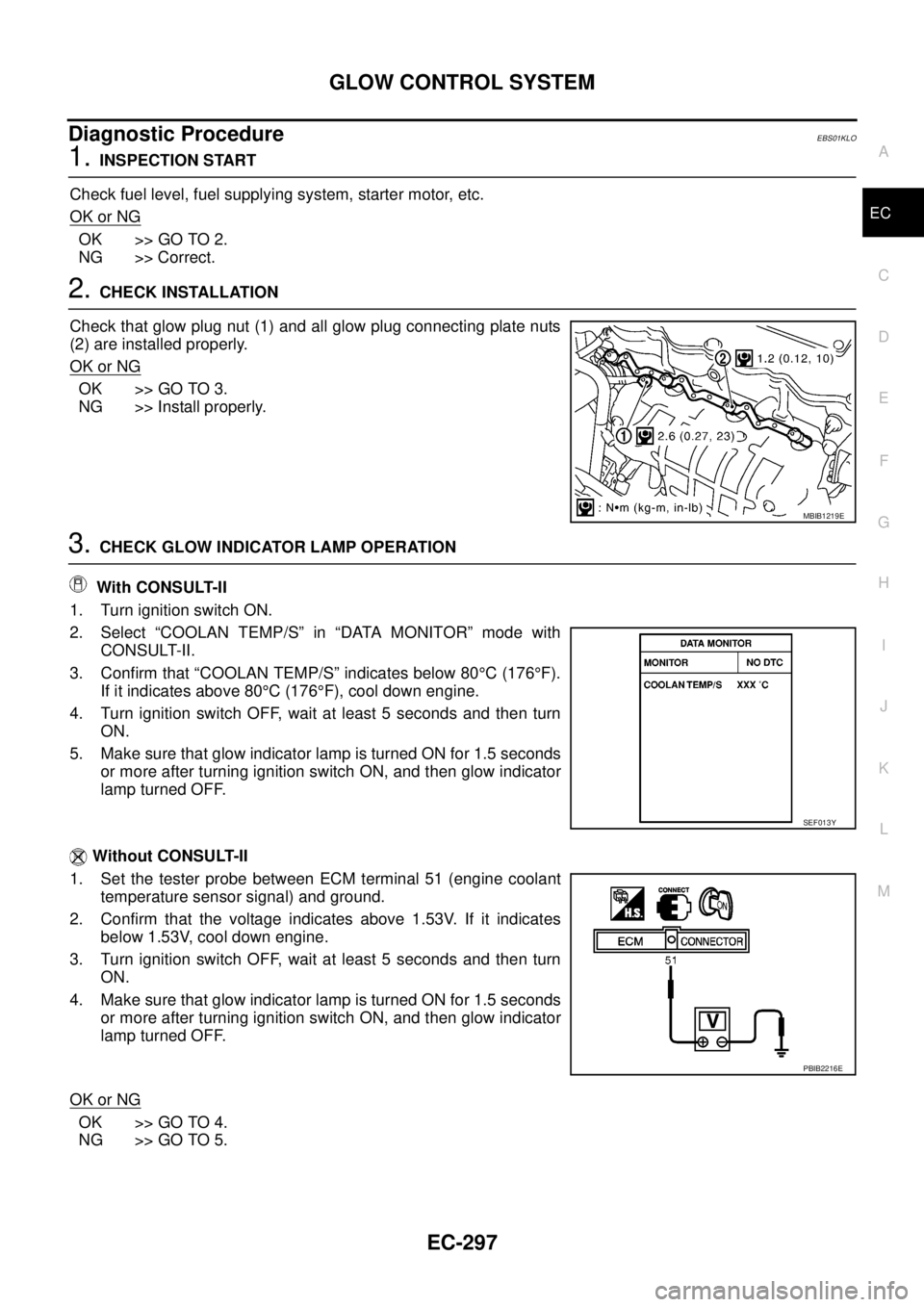
Check that glow plug nut (1) and all glow plug connecting plate nuts
(2) are installed properly.
OK or NG
OK >> GO TO 3.
NG >> Install properly.
3.CHECK GLOW INDICATOR LAMP OPERATION
With CONSULT-II
1. Turn ignition switch ON.
2. Select “COOLAN TEMP/S” in “DATA MONITOR” mode with
CONSULT-II.
3. Confirm that “COOLAN TEMP/S” indicates below 80°C(176°F).
If it indicates above 80°C(176°F), cool down engine.
4. Turn ignition switch OFF, wait at least 5 seconds and then turn
ON.
5. Make sure that glow indicator lamp is turned ON for 1.5 seconds
or more after turning ignition switch ON, and then glow indicator
lamp turned OFF.
Without CONSULT-II
1. Set the tester probe between ECM terminal 51 (engine coolant
temperature sensor signal) and ground.
2. Confirm that the voltage indicates above 1.53V. If it indicates
below 1.53V, cool down engine.
3. Turn ignition switch OFF, wait at least 5 seconds and then turn
ON.
4. Make sure that glow indicator lamp is turned ON for 1.5 seconds
or more after turning ignition switch ON, and then glow indicator
lamp turned OFF.
OK or NG
OK >> GO TO 4.
NG >> GO TO 5.
MBIB1219E
SEF013Y
PBIB2216E
Page 1278 of 3171

EC-298
GLOW CONTROL SYSTEM
4.CHECK GLOW CONTROL SYSTEM OVERALL FUNCTION
With CONSULT-II
1. Select “COOLAN TEMP/S” in “DATA MONITOR” mode with
CONSULT-II.
2. Confirm that “COOLAN TEMP/S” indicates approximately 25°C
(77°F). If NG, cool down engine.
3. Turn ignition switch OFF.
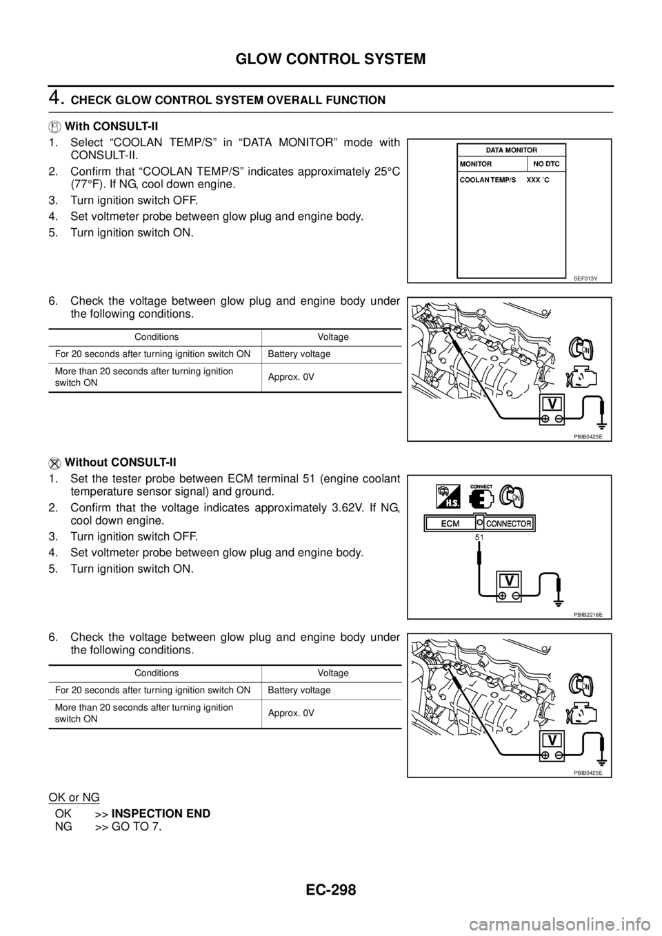
4. Set voltmeter probe between glow plug and engine body.
5. Turn ignition switch ON.
6. Check the voltage between glow plug and engine body under
the following conditions.
Without CONSULT-II
1. Set the tester probe between ECM terminal 51 (engine coolant
temperature sensor signal) and ground.
2. Confirm that the voltage indicates approximately 3.62V. If NG,
cool down engine.
3. Turn ignition switch OFF.
4. Set voltmeter probe between glow plug and engine body.
5. Turn ignition switch ON.
6. Check the voltage between glow plug and engine body under
the following conditions.
OK or NG
OK >>INSPECTION END
NG >> GO TO 7.
SEF013Y
Conditions Voltage
For 20 seconds after turning ignition switch ON Battery voltage
More than 20 seconds after turning ignition
switch ONApprox. 0V
PBIB0425E
PBIB2216E
Conditions Voltage
For 20 seconds after turning ignition switch ON Battery voltage
More than 20 seconds after turning ignition
switch ONApprox. 0V
PBIB0425E
Page 1283 of 3171

EGR VOLUME CONTROL SYSTEM
EC-303
C
D
E
F
G
H
I
J
K
L
MA
EC
CONSULT-II Reference Value in Data Monitor ModeEBS01KLS
Specification data are reference values.
ECM Terminals and Reference ValueEBS01KLT
Specification data are reference values and are measured between each terminal and ground.
CAUTION:
Do not use ECM ground terminals when measuring input/output voltage. Doing so may result in dam-
age to the ECM's transistor. Use a ground other than ECM terminals, such as the ground.
MONITOR ITEM CONDITION SPECIFICATION
EGR VOL CON/V
lEngine: After warming up
lAir conditioner switch: OFF
lShift lever: P or N (A/T), Neutral (M/T)
lNo loadAfter 1 minute at idle More than 10 steps
Revving engine from idle to 3,200
rpm0step
TERMI-
NAL
NO.WIRE
COLORITEM CONDITIONDATA
(DC Voltage)
25
26
27
28Y
O
GR
VEGR volume control valve[Engine is running]
lWarm-up condition
lIdle speed0.1 - 14V
(Voltage signals of each ECM ter-
minals differ according to the con-
trol position of EGR volume
control valve.)
105
11 3BR
BRECM relay (self shut-off)[Ignition switch ON]
[Ignition switch OFF]
lFor a few seconds after turning ignition switch
OFFApproximately 1.0V
[Ignition switch OFF]
lMore than a few seconds passed after turning
ignition switch OFFBATTERY VOLTAGE
(11 - 14V)
11 9
120R
GPower supply for ECM[Ignition switch ON]BATTERY VOLTAGE
(11 - 14V)
Page 1287 of 3171
EGR VOLUME CONTROL SYSTEM
EC-307
C
D
E
F
G
H
I
J
K
L
MA
EC
Component InspectionEBS01KLW
EGR VOLUME CONTROL VALVE
With CONSULT-II
1. Disconnect EGR volume control valve (1) harness connector.
l: Vehicle front
2. Check resistance between the following terminals.
lterminal 2 and terminals 1, 3
lterminal 5 and terminals 4, 6
If NG, replace EGR volume control valve.
IfOK,gotonextstep.
3. Remove EGR volume control valve from cylinder head.
4. Reconnect EGR volume control valve harness connector.
5. Turn ignition switch ON.
6. Perform “EGR VOL CONT/V” in “ACTIVE TEST” mode with CONSULT-II. Check that EGR volume control
valve shaft moves smoothly forward and backward according to the valve opening.
If NG, replace the EGR volume control valve.
NOTE:
When installing the EGR volume control valve, make sure that the shaft is in the same position before
checking.
MBIB1227E
Temperature°C(°F) ResistanceW
20 (68) 13 - 17
MBIB0007E
SEF819Y