2005 NISSAN NAVARA ECO mode
[x] Cancel search: ECO modePage 1158 of 3171
EC-178
DTC P0341 CMP SENSOR
On Board Diagnosis Logic
EBS01KHB
NOTE:
If DTC P0341 is displayed with DTC P0652 or P0653, first perform the trouble diagnosis for DTC P0652
or P0653. Refer toEC-227, "
DTC P0652, P0653 SENSOR POWER SUPPLY".
DTC Confirmation ProcedureEBS01KHC
NOTE:
If DTC Confirmation Procedure has been previously conducted, always turn ignition switch OFF and wait at
least 10 seconds before conducting the next test.
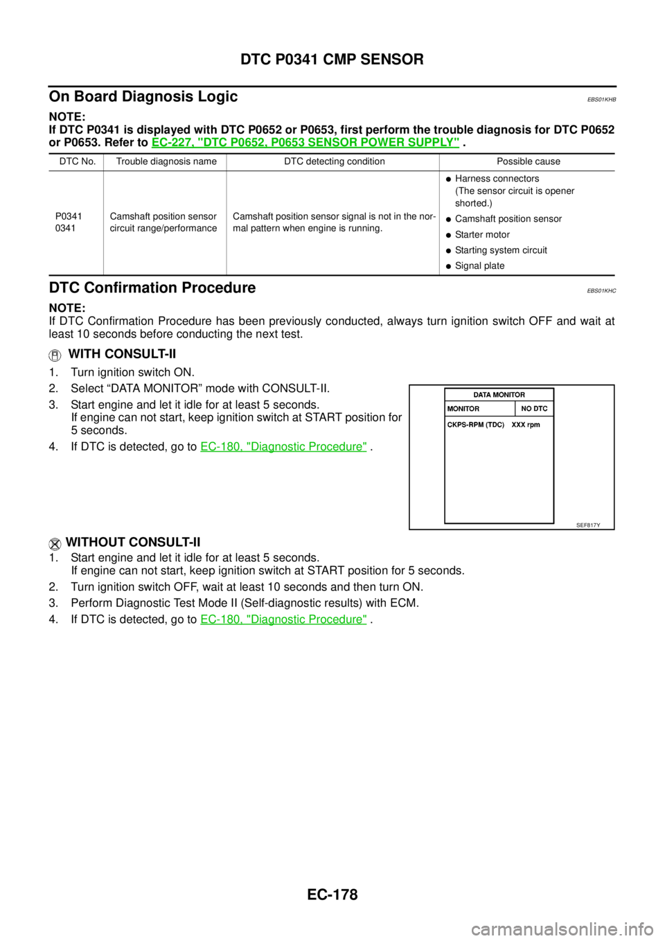
WITH CONSULT-II
1. Turn ignition switch ON.
2. Select “DATA MONITOR” mode with CONSULT-II.
3. Start engine and let it idle for at least 5 seconds.
If engine can not start, keep ignition switch at START position for
5 seconds.
4. If DTC is detected, go toEC-180, "
Diagnostic Procedure".
WITHOUT CONSULT-II
1. Start engine and let it idle for at least 5 seconds.
If engine can not start, keep ignition switch at START position for 5 seconds.
2. Turn ignition switch OFF, wait at least 10 seconds and then turn ON.
3. Perform Diagnostic Test Mode II (Self-diagnostic results) with ECM.
4. If DTC is detected, go toEC-180, "
Diagnostic Procedure".
DTC No. Trouble diagnosis name DTC detecting condition Possible cause
P0341
0341Camshaft position sensor
circuit range/performanceCamshaft position sensor signal is not in the nor-
mal pattern when engine is running.
lHarness connectors
(The sensor circuit is opener
shorted.)
lCamshaft position sensor
lStarter motor
lStarting system circuit
lSignal plate
SEF817Y
Page 1163 of 3171
DTC P0501 ASCD VEHICLE SPEED SENSOR
EC-183
C
D
E
F
G
H
I
J
K
L
MA
EC
DTC P0501 ASCD VEHICLE SPEED SENSORPFP:24810
Component DescriptionEBS01KHH
The ECM receives vehicle speed sensor signal via CAN communication line. It is sent from combination
meter. The ECM uses this signal for ASCD control. Refer toEC-355, "
AUTOMATIC SPEED CONTROL
DEVICE (ASCD)"for ASCD functions.
On Board Diagnosis LogicEBS01KHI
The MI will not light up for this self-diagnosis.
NOTE:
lIf DTC P0501 is displayed with DTC U1000 first perform the trouble diagnosis for DTC U1000. Refer
toEC-79, "
DTC U1000 CAN COMMUNICATION LINE".
lIf DTC P0501 is displayed with DTC P0606, first perform the trouble diagnosis for DTC P0606.
Refer toEC-215, "
DTC P0606 ECM".
DTC Confirmation ProcedureEBS01KHJ
CAUTION:
Always drive vehicle at a safe speed.
NOTE:
If DTC Confirmation Procedure has been previously conducted, always turn ignition switch OFF and wait at
least 10 seconds before conducting the next test.
TESTING CONDITION:
Step 3 may be conducted with the drive wheels lifted in the shop or by driving the vehicle. If a road test
is expected to be easier, it is unnecessary to lift the vehicle.
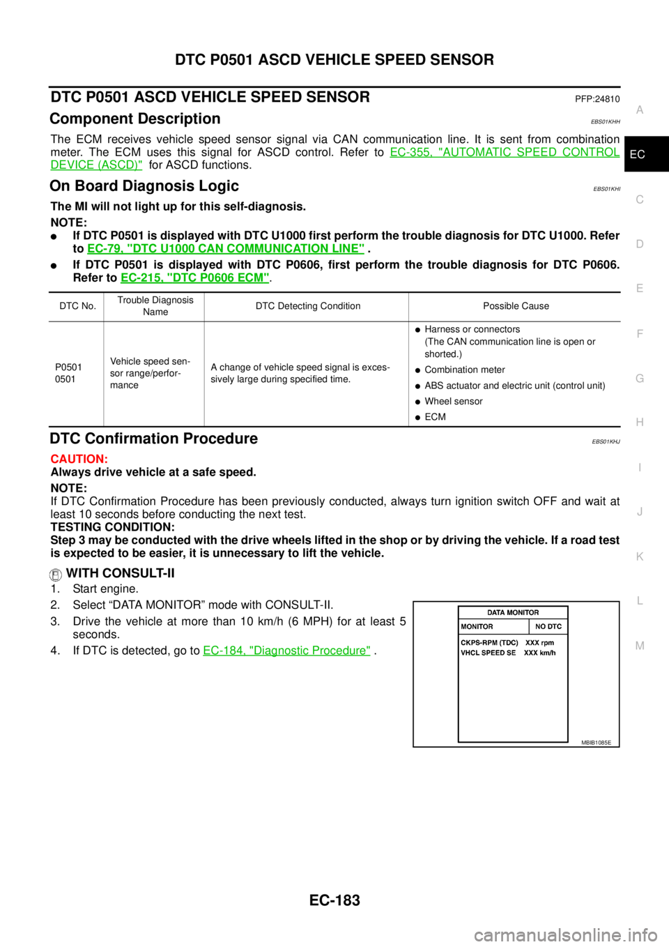
WITH CONSULT-II
1. Start engine.
2. Select “DATA MONITOR” mode with CONSULT-II.
3. Drive the vehicle at more than 10 km/h (6 MPH) for at least 5
seconds.
4. If DTC is detected, go toEC-184, "
Diagnostic Procedure".
DTC No.Trouble Diagnosis
NameDTC Detecting Condition Possible Cause
P0501
0501Vehicle speed sen-
sor range/perfor-
manceA change of vehicle speed signal is exces-
sively large during specified time.
lHarness or connectors
(The CAN communication line is open or
shorted.)
lCombination meter
lABS actuator and electric unit (control unit)
lWheel sensor
lECM
SEF058YMBIB1085E
Page 1164 of 3171
EC-184
DTC P0501 ASCD VEHICLE SPEED SENSOR
WITHOUT CONSULT-II
TESTING CONDITION:
Step 2 may be conducted with the drive wheels lifted in the shop or by driving the vehicle. If a road test
is expected to be easier, it is unnecessary to lift the vehicle.
1. Start engine.
2. Drivethevehicleatmorethan10km/h(6MPH).
3. Turn ignition switch OFF, wait at least 10 seconds and then turn ON.
4. Perform Diagnostic Test Mode II (Self-diagnostic results) with ECM.
5. If DTC is detected, go toEC-184, "
Diagnostic Procedure".
Diagnostic ProcedureEBS01KHK
1.CHECK DTC WITH ABS ACTUATOR AND ELECTRIC UNIT (CONTROL UNIT)
Refer toBRC-8, "
TROUBLE DIAGNOSIS".
OK or NG
OK >> GO TO 2.
NG >> Repair or replace.
2.CHECK COMBINATION METER
Check combination meter function.
Refer toDI-4, "
COMBINATION METERS".
>>INSPECTION END
Page 1165 of 3171
DTC P0502 ASCD VEHICLE SPEED SENSOR
EC-185
C
D
E
F
G
H
I
J
K
L
MA
EC
DTC P0502 ASCD VEHICLE SPEED SENSORPFP:24810
Component DescriptionEBS01KHL
The ECM receives vehicle speed sensor signal via CAN communication line. It is sent from combination
meter. The ECM uses this signal for ASCD control. Refer toEC-355, "
AUTOMATIC SPEED CONTROL
DEVICE (ASCD)"for ASCD functions.
On Board Diagnosis LogicEBS01KHM
The MI will not light up for this self-diagnosis.
NOTE:
lIf DTC P0502 is displayed with DTC U1000 first perform the trouble diagnosis for DTC U1000. Refer
toEC-79, "
DTC U1000 CAN COMMUNICATION LINE".
lIf DTC P0502 is displayed with DTC P0606, first perform the trouble diagnosis for DTC P0606.
Refer toEC-215, "
DTC P0606 ECM".
DTC Confirmation ProcedureEBS01KHN
CAUTION:
Always drive vehicle at a safe speed.
NOTE:
If DTC Confirmation Procedure has been previously conducted, always turn ignition switch OFF and wait at
least 10 seconds before conducting the next test.
TESTING CONDITION:
Step 3 may be conducted with the drive wheels lifted in the shop or by driving the vehicle. If a road test
is expected to be easier, it is unnecessary to lift the vehicle.
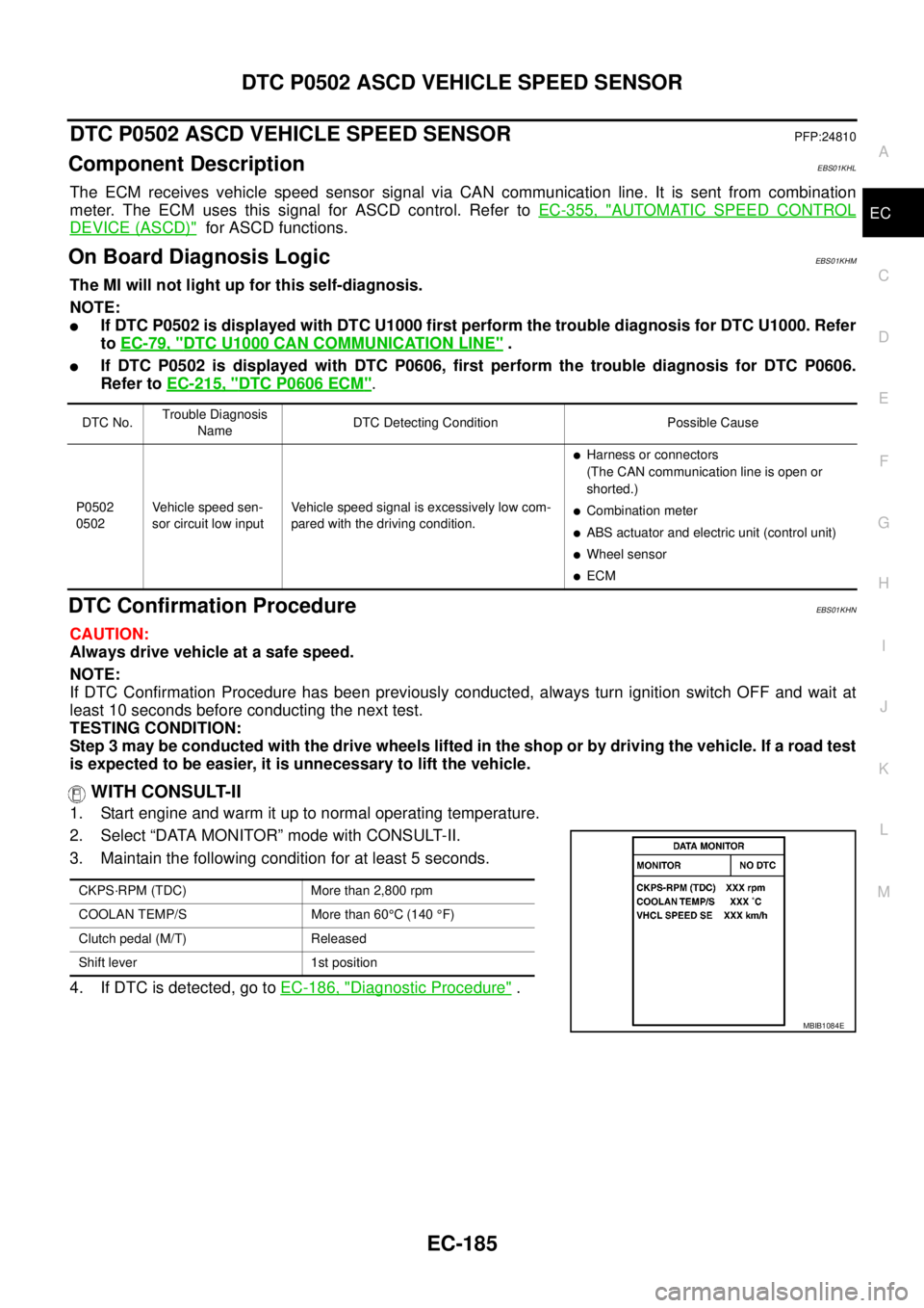
WITH CONSULT-II
1. Start engine and warm it up to normal operating temperature.
2. Select “DATA MONITOR” mode with CONSULT-II.
3. Maintain the following condition for at least 5 seconds.
4. If DTC is detected, go toEC-186, "
Diagnostic Procedure".
DTC No.Trouble Diagnosis
NameDTC Detecting Condition Possible Cause
P0502
0502Vehicle speed sen-
sor circuit low inputVehicle speed signal is excessively low com-
pared with the driving condition.
lHarness or connectors
(The CAN communication line is open or
shorted.)
lCombination meter
lABS actuator and electric unit (control unit)
lWheel sensor
lECM
CKPS·RPM (TDC) More than 2,800 rpm
COOLAN TEMP/S More than 60°C (140°F)
Clutch pedal (M/T) Released
Shift lever 1st position
MBIB1084E
Page 1166 of 3171
EC-186
DTC P0502 ASCD VEHICLE SPEED SENSOR
WITHOUT CONSULT-II
TESTING CONDITION:
Step 2 may be conducted with the drive wheels lifted in the shop or by driving the vehicle. If a road test
is expected to be easier, it is unnecessary to lift the vehicle.
1. Start engine and warm it up to normal operating temperature.
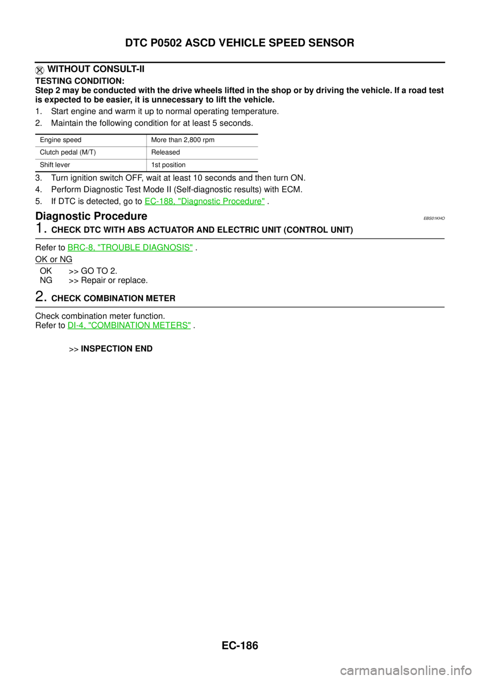
2. Maintain the following condition for at least 5 seconds.
3. Turn ignition switch OFF, wait at least 10 seconds and then turn ON.
4. Perform Diagnostic Test Mode II (Self-diagnostic results) with ECM.
5. If DTC is detected, go toEC-188, "
Diagnostic Procedure".
Diagnostic ProcedureEBS01KHO
1.CHECK DTC WITH ABS ACTUATOR AND ELECTRIC UNIT (CONTROL UNIT)
Refer toBRC-8, "
TROUBLE DIAGNOSIS".
OK or NG
OK >> GO TO 2.
NG >> Repair or replace.
2.CHECK COMBINATION METER
Check combination meter function.
Refer toDI-4, "
COMBINATION METERS".
>>INSPECTION END
Engine speed More than 2,800 rpm
Clutch pedal (M/T) Released
Shift lever 1st position
Page 1167 of 3171
DTC P0503 ASCD VEHICLE SPEED SENSOR
EC-187
C
D
E
F
G
H
I
J
K
L
MA
EC
DTC P0503 ASCD VEHICLE SPEED SENSORPFP:24810
Component DescriptionEBS01KHP
The ECM receives vehicle speed sensor signal via CAN communication line. It is sent from combination
meter. The ECM uses this signal for ASCD control. Refer toEC-355, "
AUTOMATIC SPEED CONTROL
DEVICE (ASCD)"for ASCD functions.
On Board Diagnosis LogicEBS01KHQ
The MI will not light up for this self-diagnosis.
NOTE:
lIf DTC P0503 is displayed with DTC U1000 first perform the trouble diagnosis for DTC U1000. Refer
toEC-79, "
DTC U1000 CAN COMMUNICATION LINE".
lIf DTC P0503 is displayed with DTC P0606, first perform the trouble diagnosis for DTC P0606.
Refer toEC-215, "
DTC P0606 ECM".
DTC Confirmation ProcedureEBS01KHR
CAUTION:
Always drive vehicle at a safe speed.
NOTE:
If DTC Confirmation Procedure has been previously conducted, always turn ignition switch OFF and wait at
least 10 seconds before conducting the next test.
TESTING CONDITION:
Step 3 may be conducted with the drive wheels lifted in the shop or by driving the vehicle. If a road test
is expected to be easier, it is unnecessary to lift the vehicle.
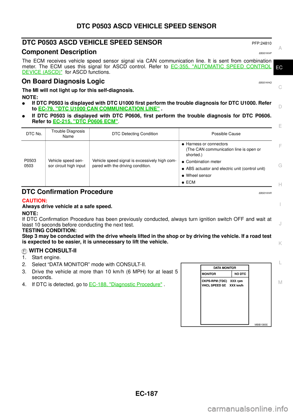
WITH CONSULT-II
1. Start engine.
2. Select “DATA MONITOR” mode with CONSULT-II.
3. Drive the vehicle at more than 10 km/h (6 MPH) for at least 5
seconds.
4. If DTC is detected, go toEC-188, "
Diagnostic Procedure".
DTC No.Trouble Diagnosis
NameDTC Detecting Condition Possible Cause
P0503
0503Vehicle speed sen-
sor circuit high inputVehicle speed signal is excessively high com-
pared with the driving condition.
lHarness or connectors
(The CAN communication line is open or
shorted.)
lCombination meter
lABS actuator and electric unit (control unit)
lWheel sensor
lECM
SEF058YMBIB1085E
Page 1168 of 3171
EC-188
DTC P0503 ASCD VEHICLE SPEED SENSOR
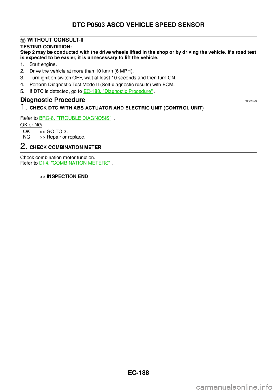
WITHOUT CONSULT-II
TESTING CONDITION:
Step 2 may be conducted with the drive wheels lifted in the shop or by driving the vehicle. If a road test
is expected to be easier, it is unnecessary to lift the vehicle.
1. Start engine.
2. Drivethevehicleatmorethan10km/h(6MPH).
3. Turn ignition switch OFF, wait at least 10 seconds and then turn ON.
4. Perform Diagnostic Test Mode II (Self-diagnostic results) with ECM.
5. If DTC is detected, go toEC-188, "
Diagnostic Procedure".
Diagnostic ProcedureEBS01KHS
1.CHECK DTC WITH ABS ACTUATOR AND ELECTRIC UNIT (CONTROL UNIT)
Refer toBRC-8, "
TROUBLE DIAGNOSIS".
OK or NG
OK >> GO TO 2.
NG >> Repair or replace.
2.CHECK COMBINATION METER
Check combination meter function.
Refer toDI-4, "
COMBINATION METERS".
>>INSPECTION END
Page 1170 of 3171
EC-190
DTC P0504 ASCD BRAKE SWITCH
On Board Diagnosis Logic
EBS01KHW
The MI will not light up for this diagnosis.
DTC confirmation ProcedureEBS01KHX
CAUTION:
Always drive vehicle at a safe speed.
NOTE:
If DTC Confirmation Procedure has been previously conducted, always turn ignition switch OFF and wait at
least 10 seconds before conducting the next test.
TESTING CONDITION:
Steps 3 and 4 may be conducted with the drive wheels lifted in the shop or by driving the vehicle. If a
road test is expected to be easier, it is unnecessary to lift the vehicle.
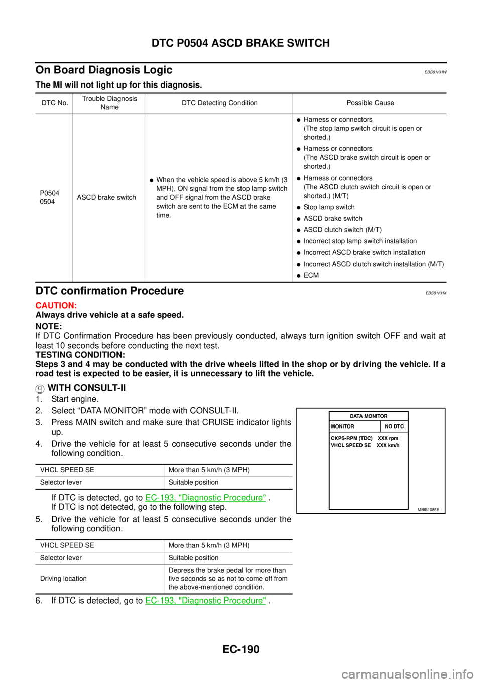
WITH CONSULT-II
1. Start engine.
2. Select “DATA MONITOR” mode with CONSULT-II.
3. Press MAIN switch and make sure that CRUISE indicator lights
up.
4. Drive the vehicle for at least 5 consecutive seconds under the
following condition.
If DTC is detected, go toEC-193, "
Diagnostic Procedure".
If DTC is not detected, go to the following step.
5. Drive the vehicle for at least 5 consecutive seconds under the
following condition.
6. If DTC is detected, go toEC-193, "
Diagnostic Procedure".
DTC No.Trouble Diagnosis
NameDTC Detecting Condition Possible Cause
P0504
0504ASCD brake switch
lWhen the vehicle speed is above 5 km/h (3
MPH), ON signal from the stop lamp switch
and OFF signal from the ASCD brake
switch are sent to the ECM at the same
time.
lHarness or connectors
(The stop lamp switch circuit is open or
shorted.)
lHarness or connectors
(The ASCD brake switch circuit is open or
shorted.)
lHarness or connectors
(The ASCD clutch switch circuit is open or
shorted.) (M/T)
lStop lamp switch
lASCD brake switch
lASCD clutch switch (M/T)
lIncorrectstoplampswitchinstallation
lIncorrect ASCD brake switch installation
lIncorrect ASCD clutch switch installation (M/T)
lECM
VHCL SPEED SE More than 5 km/h (3 MPH)
Selector lever Suitable position
VHCL SPEED SE More than 5 km/h (3 MPH)
Selector lever Suitable position
Driving locationDepress the brake pedal for more than
five seconds so as not to come off from
the above-mentioned condition.
MBIB1085E