2005 NISSAN NAVARA ECO mode
[x] Cancel search: ECO modePage 1208 of 3171
EC-228
DTC P0652, P0653 SENSOR POWER SUPPLY
On Board Diagnosis Logic
EBS01KIZ
The MI will not light up for these self-diagnoses.
DTC Confirmation ProcedureEBS01KJ0
NOTE:
If DTC Confirmation Procedure has been previously conducted, always turn ignition switch OFF and wait at
least 10 seconds before conducting the next test.
WITH CONSULT-II
1. Turn ignition switch ON.
2. Select “DATA MONITOR” mode with CONSULT-II.
3. Wait at least 5 seconds.
4. If DTC is detected, go toEC-230, "
Diagnostic Procedure".
WITHOUT CONSULT-II
1. Turn ignition switch ON and wait at least 5 seconds.
2. Turn ignition switch OFF, wait at least 10 seconds and then turn ON.
3. Perform Diagnostic Test Mode II (Self-diagnostic results) with ECM.
4. If DTC is detected, go toEC-230, "
Diagnostic Procedure".
DTC No. Trouble diagnosis name DTC detecting condition Possible cause
P0652
0652Sensor power supply cir-
cuit lowECM detects a voltage of power source
forsensorisexcessivelylow.
lHarness or connectors
(APP sensor 2 power supply circuit is shorted.)
(Crankshaft position sensor circuit is shorted.)
(Camshaft position sensor circuit is shorted.)
(Fuel rail pressure sensor circuit is shorted.)
(Refrigerant pressure sensor circuit is shorted.)
(Turbocharger boost sensor circuit is shorted.)
lAccelerator pedal position sensor
(APP sensor 2)
lCrankshaft position sensor
lCamshaft position sensor
lFuel rail pressure sensor
lRefrigerant pressure sensor
lTurbocharger boost sensor P0653
0653Sensor power supply cir-
cuit highECM detects a voltage of power source
for sensor is excessively high.
SEF817Y
Page 1212 of 3171
EC-232
DTC P0686 ECM RELAY
DTC P0686 ECM RELAY
PFP:25230
ECM Terminals and Reference valveEBS01KJ3
Specification data are reference values and are measured between each terminal and ground.
CAUTION:
Do not use ECM ground terminals when measuring input/output voltage. Doing so may result in dam-
age to the ECM's transistor. Use a ground other than ECM terminals, such as the ground.
On Board Diagnosis LogicEBS01KJ4
The MI will not light up for this self-diagnosis.
DTC Confirmation ProcedureEBS01KJ5
NOTE:
If DTC Confirmation Procedure has been previously conducted, always turn ignition switch OFF and wait at
least 10 seconds before conducting the next test.
WITH CONSULT-II
1. Turn ignition switch ON and then turn OFF.
2. Wait at least 30 seconds.
3. Turn ignition switch ON.
4. Select “DATA MONITOR” mode with CONSULT-II.
5. If DTC is detected, go toEC-235, "
Diagnostic Procedure".
WITHOUT CONSULT-II
1. Turn ignition switch ON and then turn OFF.
2. Wait at least 30 seconds.
3. Turn ignition switch ON.
4. Turn ignition switch OFF, wait at least 10 seconds and then turn ON.
TERMI-
NAL
NO.WIRE
COLORITEM CONDITIONDATA
(DC Voltage)
105
11 3BR
BRECM relay (self shut-off)[Ignition switch ON]
[Ignition switch OFF]
lFor a few seconds after turning ignition
switch OFFApproximately 1.0V
[Ignition switch OFF]
lMore than a few seconds after turning igni-
tion switch OFFBATTERY VOLTAGE
(11 - 14V)
107
108R
RIgnition switch[Ignition switch ON]BATTERY VOLTAGE
(11 - 14V)
11 9
120R
GPower supply for ECM[Ignition switch ON]BATTERY VOLTAGE
(11 - 14V)
DTC No. Trouble diagnosis name DTC detecting condition Possible cause
P0686
0686ECM relay circuitECM detects ECM relay is stuck closed even if
ignition switch OFF.
lHarness or connectors
(The ECM relay circuit is shorted.)
lECM relay
SEF817Y
Page 1219 of 3171
DTC P1268 - P1271 FUEL INJECTOR
EC-239
C
D
E
F
G
H
I
J
K
L
MA
EC
DTC Confirmation ProcedureEBS01KJC
CAUTION:
Always drive vehicle in safe manner according to traffic conditions and obey all traffic laws when driv-
ing.
NOTE:
If DTC Confirmation Procedure has been previously conducted, always turn ignition switch OFF and wait at
least 10 seconds before conducting the next test.
WITH CONSULT-II
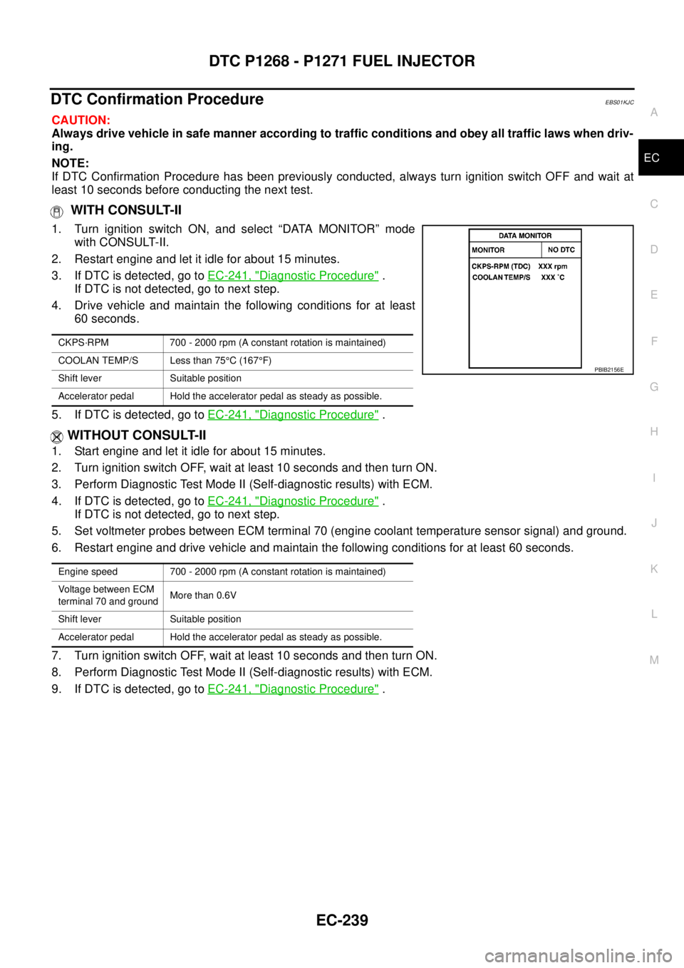
1. Turn ignition switch ON, and select “DATA MONITOR” mode
with CONSULT-II.
2. Restart engine and let it idle for about 15 minutes.
3. If DTC is detected, go toEC-241, "
Diagnostic Procedure".
If DTC is not detected, go to next step.
4. Drive vehicle and maintain the following conditions for at least
60 seconds.
5. If DTC is detected, go toEC-241, "
Diagnostic Procedure".
WITHOUT CONSULT-II
1. Start engine and let it idle for about 15 minutes.
2. Turn ignition switch OFF, wait at least 10 seconds and then turn ON.
3. Perform Diagnostic Test Mode II (Self-diagnostic results) with ECM.
4. If DTC is detected, go toEC-241, "
Diagnostic Procedure".
If DTC is not detected, go to next step.
5. Set voltmeter probes between ECM terminal 70 (engine coolant temperature sensor signal) and ground.
6. Restart engine and drive vehicle and maintain the following conditions for at least 60 seconds.
7. Turn ignition switch OFF, wait at least 10 seconds and then turn ON.
8. Perform Diagnostic Test Mode II (Self-diagnostic results) with ECM.
9. If DTC is detected, go toEC-241, "
Diagnostic Procedure".
CKPS·RPM 700 - 2000 rpm (A constant rotation is maintained)
COOLAN TEMP/S Less than 75°C (167°F)
Shift lever Suitable position
Accelerator pedal Hold the accelerator pedal as steady as possible.
PBIB2156E
Engine speed 700 - 2000 rpm (A constant rotation is maintained)
Voltage between ECM
terminal 70 and groundMore than 0.6V
Shift lever Suitable position
Accelerator pedal Hold the accelerator pedal as steady as possible.
Page 1221 of 3171
DTC P1268 - P1271 FUEL INJECTOR
EC-241
C
D
E
F
G
H
I
J
K
L
MA
EC
Diagnostic ProcedureEBS01KJE
1.CHECK INJECTOR ADJUSTMENT VALUE
1. Turn ignition switch ON.
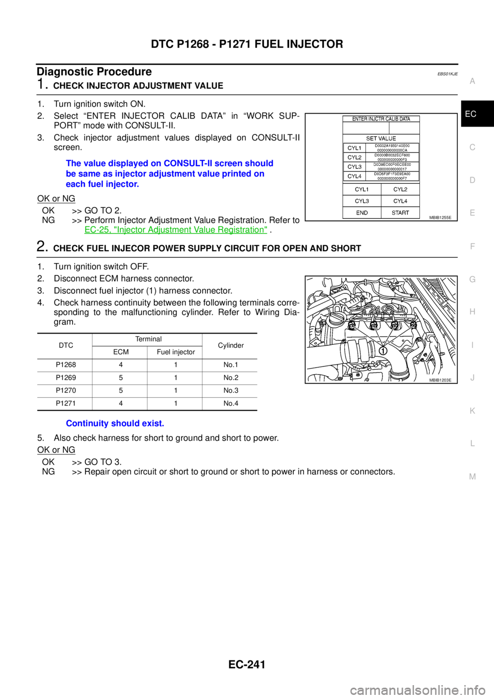
2. Select “ENTER INJECTOR CALIB DATA” in “WORK SUP-
PORT” mode with CONSULT-II.
3. Check injector adjustment values displayed on CONSULT-II
screen.
OK or NG
OK >> GO TO 2.
NG >> Perform Injector Adjustment Value Registration. Refer to
EC-25, "
Injector Adjustment Value Registration".
2.CHECK FUEL INJECOR POWER SUPPLY CIRCUIT FOR OPEN AND SHORT
1. Turn ignition switch OFF.
2. Disconnect ECM harness connector.
3. Disconnect fuel injector (1) harness connector.
4. Check harness continuity between the following terminals corre-
sponding to the malfunctioning cylinder. Refer to Wiring Dia-
gram.
5. Also check harness for short to ground and short to power.
OK or NG
OK >> GO TO 3.
NG >> Repair open circuit or short to ground or short to power in harness or connectors.The value displayed on CONSULT-II screen should
be same as injector adjustment value printed on
each fuel injector.
MBIB1255E
DTCTe r m i n a l
Cylinder
ECM Fuel injector
P1268 4 1 No.1
P1269 5 1 No.2
P1270 5 1 No.3
P1271 4 1 No.4
Continuity should exist.
MBIB1203E
Page 1223 of 3171
DTC P1268 - P1271 FUEL INJECTOR
EC-243
C
D
E
F
G
H
I
J
K
L
MA
EC
5.CHECK FUEL INJECTOR-II
With CONSULT-II
1. Remove two fuel injectors.
NOTE:
One is from malfunctioning cylinder and the other is from any cylinder other than the malfunctioning cylin-
der.
2. Swap the two fuel injectors to the other cylinder.
3. Reconnect ECM harness connector and fuel injector harness connector.
4. Turn ignition switch ON.
5. Perform Injector Adjustment Value Registration. Refer toEC-25, "
Injector Adjustment Value Registration".
6. Select “SELF DIAG RESULTS” mode with CONSULT-II.
7. Touch “ERASE”.
8. PerformEC-239, "
DTC Confirmation Procedure".
9. Is DTC displayed for the other cylinder?
Without CONSULT-II
1. Remove two fuel injectors.
NOTE:
One is from malfunctioning cylinder and the other is from any cylinder other than the malfunctioning cylin-
der.
2. Swap the two fuel injectors to the other cylinder.
3. Reconnect ECM harness connector and fuel injector harness connector.
4. Turn ignition switch ON.
5. Perform Injector Adjustment Value Registration. Refer toEC-25, "
Injector Adjustment Value Registration".
6. Erase the Diagnostic Test Mode II (Self-diagnostic results) memory. Refer toEC-27
.
7. PerformEC-239, "
DTC Confirmation Procedure".
8. Is DTC displayed for the other cylinder?
Ye s o r N o
Ye s > > G O T O 6 .
No >> GO TO 7.
6.REPLACE FUEL INJECOR
1. Replace fuel injector of malfunctioning cylinder.
2. Perform Injector Adjustment Value Registration. Refer toEC-25, "
Injector Adjustment Value Registration".
>>INSPECTION END
7.CHECK INTERMITTENT INCIDENT
Refer toEC-70, "
TROUBLE DIAGNOSIS FOR INTERMITTENT INCIDENT".
>>INSPECTION END
Component InspectionEBS01KJF
FUEL INJECTOR
1. Disconnect fuel injector harness connector.
Page 1226 of 3171
EC-246
DTC P1272 FUEL PUMP
: Average voltage for pulse signal (Actual pulse signal can be confirmed by oscilloscope.)
On Board Diagnosis LogicEBS01KJK
The MI will not light up for this self-diagnosis.
NOTE:
If DTC P1272 is displayed with DTC P0652 or P0653, first perform the trouble diagnosis for DTC P0652
or P0653. Refer toEC-227, "
DTC P0652, P0653 SENSOR POWER SUPPLY".
DTC Confirmation ProcedureEBS01KJL
NOTE:
If DTC Confirmation Procedure has been previously conducted, always turn ignition switch OFF and wait at
least 10 seconds before conducting the next test.
WITH CONSULT-II
1. Turn ignition switch ON.
2. Select “DATA MONITOR” mode with CONSULT-II.
3. Start engine and keep engine speed more than 4,000 rpm for at
least 5 seconds, then release the accelerator pedal.
4. If DTC is detected, go toEC-249, "
Diagnostic Procedure".
WITHOUT CONSULT-II
1. Start engine and keep engine speed more than 4,000 rpm for at least 5 seconds, then release the acceler-
ator pedal.
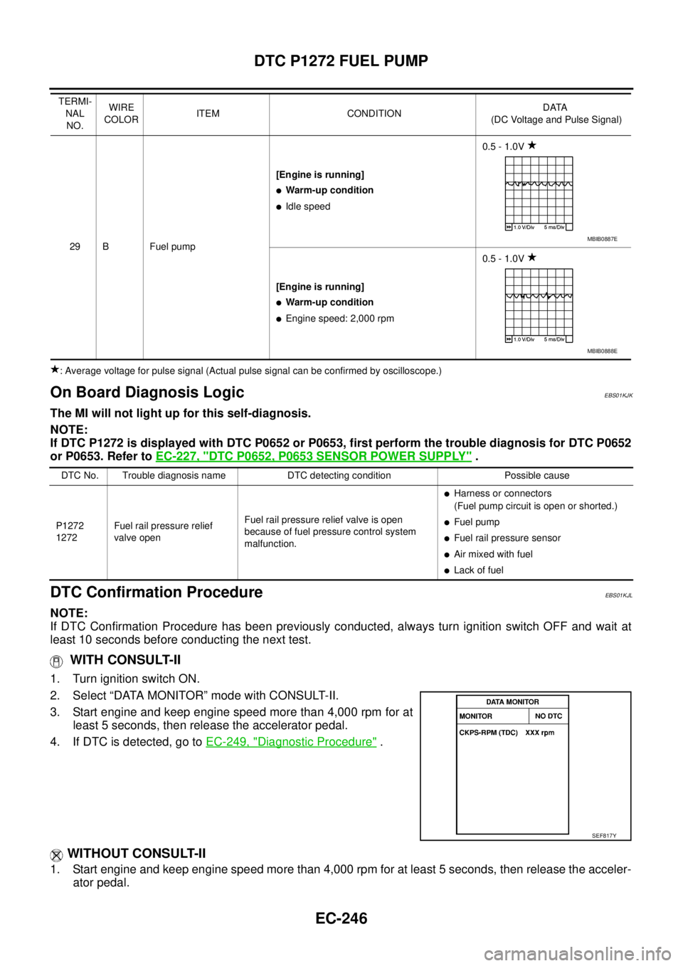
29 B Fuel pump[Engine is running]
lWarm-up condition
lIdle speed0.5 - 1.0V
[Engine is running]
lWarm-up condition
lEngine speed: 2,000 rpm0.5 - 1.0V TERMI-
NAL
NO.WIRE
COLORITEM CONDITIONDATA
(DC Voltage and Pulse Signal)
MBIB0887E
MBIB0888E
DTC No. Trouble diagnosis name DTC detecting condition Possible cause
P1272
1272Fuel rail pressure relief
valve openFuel rail pressure relief valve is open
because of fuel pressure control system
malfunction.
lHarness or connectors
(Fuel pump circuit is open or shorted.)
lFuel pump
lFuel rail pressure sensor
lAir mixed with fuel
lLack of fuel
SEF817Y
Page 1227 of 3171

DTC P1272 FUEL PUMP
EC-247
C
D
E
F
G
H
I
J
K
L
MA
EC
2. Turn ignition switch OFF, wait at least 10 seconds and then turn ON.
3. Perform Diagnostic Test Mode II (Self-diagnostic results) with ECM.
4. If DTC is detected, go toEC-249, "
Diagnostic Procedure".
Page 1229 of 3171
DTC P1272 FUEL PUMP
EC-249
C
D
E
F
G
H
I
J
K
L
MA
EC
Diagnostic ProcedureEBS01KJN
1.PERFORM FUEL PUMP LEARNING VALUE CLEARING
NOTE:
If the DTC is detected because of air mixed with fuel (i.e.: caused by lack of fuel), it may become normal by
performing following procedure.
With CONSULT-II
1. Turn ignition switch ON.
2. Perform Fuel Pump Learning Value Clearing. Refer toEC-24, "
Fuel Pump Learning Value Clearing".
3. Start engine and let it idle for at least 60 seconds.
4. Select “SELF-DIAG RESULT” mode with CONSULT-II.
5. Touch “ERASE”.
6. PerformEC-246, "
DTC Confirmation Procedure", again.
7. Is DTC detected again?
Without CONSULT-II
1. Turn ignition switch ON.
2. Perform Fuel Pump Learning Value Clearing. Refer toEC-24, "
Fuel Pump Learning Value Clearing".
3. Start engine and let it idle for at least 60 seconds.
4. Erase the Diagnostic Test Mode II (Self-diagnostic results) memory. Refer toEC-27
.
5. PerformEC-246, "
DTC Confirmation Procedure", again.
6. Is DTC displayed again?
Ye s o r N o
Ye s > > G O T O 2 .
No >>INSPECTION END
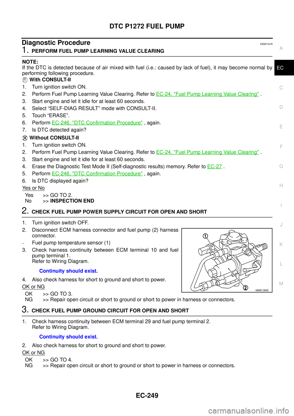
2.CHECK FUEL PUMP POWER SUPPLY CIRCUIT FOR OPEN AND SHORT
1. Turn ignition switch OFF.
2. Disconnect ECM harness connector and fuel pump (2) harness
connector.
–Fuel pump temperature sensor (1)
3. Check harness continuity between ECM terminal 10 and fuel
pump terminal 1.
Refer to Wiring Diagram.
4. Also check harness for short to ground and short to power.
OK or NG
OK >> GO TO 3.
NG >> Repair open circuit or short to ground or short to power in harness or connectors.
3.CHECK FUEL PUMP GROUND CIRCUIT FOR OPEN AND SHORT
1. Check harness continuity between ECM terminal 29 and fuel pump terminal 2.
Refer to Wiring Diagram.
2. Also check harness for short to ground and short to power.
OK or NG
OK >> GO TO 4.
NG >> Repair open circuit or short to ground or short to power in harness or connectors.
Continuity should exist.
MBIB1389E
Continuity should exist.