2005 NISSAN NAVARA ECO mode
[x] Cancel search: ECO modePage 1005 of 3171
BASIC SERVICE PROCEDURE
EC-25
C
D
E
F
G
H
I
J
K
L
MA
EC
Injector Adjustment Value RegistrationEBS01KCM
DESCRIPTION
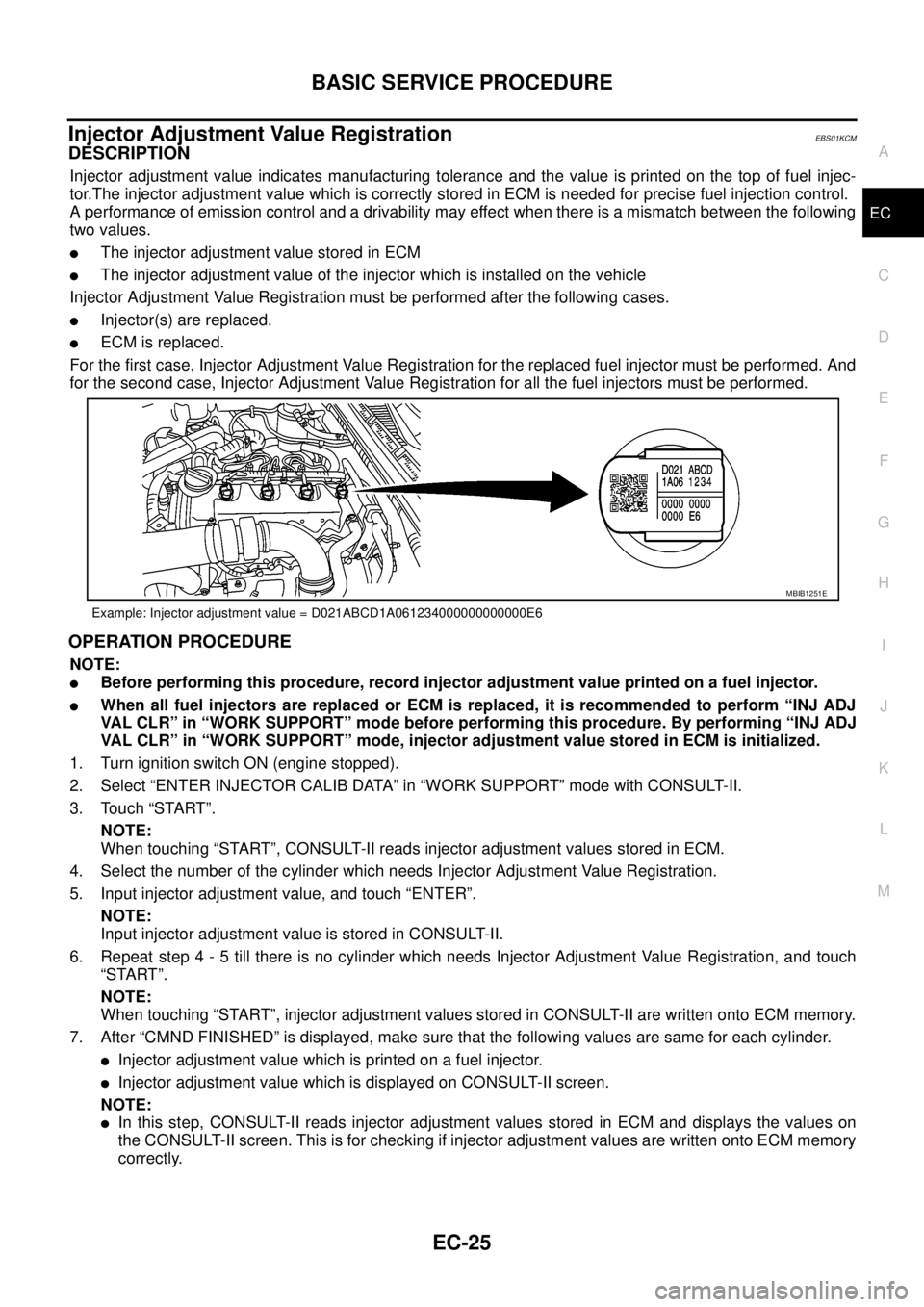
Injector adjustment value indicates manufacturing tolerance and the value is printed on the top of fuel injec-
tor.The injector adjustment value which is correctly stored in ECM is needed for precise fuel injection control.
A performance of emission control and a drivability may effect when there is a mismatch between the following
two values.
lThe injector adjustment value stored in ECM
lThe injector adjustment value of the injector which is installed on the vehicle
Injector Adjustment Value Registration must be performed after the following cases.
lInjector(s) are replaced.
lECM is replaced.
For the first case, Injector Adjustment Value Registration for the replaced fuel injector must be performed. And
for the second case, Injector Adjustment Value Registration for all the fuel injectors must be performed.
OPERATION PROCEDURE
NOTE:
lBefore performing this procedure, record injector adjustment value printed on a fuel injector.
lWhen all fuel injectors are replaced or ECM is replaced, it is recommended to perform “INJ ADJ
VAL CLR” in “WORK SUPPORT” mode before performing this procedure. By performing “INJ ADJ
VAL CLR” in “WORK SUPPORT” mode, injector adjustment value stored in ECM is initialized.
1. Turn ignition switch ON (engine stopped).
2. Select “ENTER INJECTOR CALIB DATA” in “WORK SUPPORT” mode with CONSULT-II.
3. Touch “START”.
NOTE:
When touching “START”, CONSULT-II reads injector adjustment values stored in ECM.
4. Select the number of the cylinder which needs Injector Adjustment Value Registration.
5. Input injector adjustment value, and touch “ENTER”.
NOTE:
Input injector adjustment value is stored in CONSULT-II.
6. Repeat step 4 - 5 till there is no cylinder which needs Injector Adjustment Value Registration, and touch
“START”.
NOTE:
When touching “START”, injector adjustment values stored in CONSULT-II are written onto ECM memory.
7. After “CMND FINISHED” is displayed, make sure that the following values are same for each cylinder.
lInjector adjustment value which is printed on a fuel injector.
lInjector adjustment value which is displayed on CONSULT-II screen.
NOTE:
lIn this step, CONSULT-II reads injector adjustment values stored in ECM and displays the values on
the CONSULT-II screen. This is for checking if injector adjustment values are written onto ECM memory
correctly.
Example: Injector adjustment value = D021ABCD1A061234000000000000E6
MBIB1251E
Page 1007 of 3171
ON BOARD DIAGNOSTIC (OBD) SYSTEM
EC-27
C
D
E
F
G
H
I
J
K
L
MA
EC
ON BOARD DIAGNOSTIC (OBD) SYSTEMPFP:00028
DTC Detection LogicEBS01KCN
When a malfunction is detected, the malfunction (DTC) and freeze frame data are stored in the ECM memory.
The MI will light up each time the ECM detects malfunction. For diagnostic items causing the MI to light up,
refer toEC-6, "
INDEX FOR DTC".
Diagnostic Trouble Code (DTC)EBS01KCO
HOW TO READ DTC
The DTC can be read by the following methods.
With CONSULT-II
CONSULT-IIdisplaystheDTCin"SELF-DIAGRESULTS"mode.Example:P0117,P0335,P1268,etc.These
DTCs are prescribed by ISO15031-5.
(CONSULT-II also displays the malfunctioning component or system.)
Without CONSULT-II
The number of blinks of the MI in the Diagnostic Test Mode II (Self-Diagnostic Results) indicates the DTC.
Example: 0117, 0335, 1260, etc.
lOutput of a DTC indicates a malfunction. However, the Diagnostic Test Mode II does not indicate
whether the malfunction is still occurring or has occurred in the past and has returned to normal.
CONSULT-II can identify malfunction status as shown below. Therefore, using CONSULT-II (if avail-
able) is recommended.
HOW TO ERASE DTC
With CONSULT-II
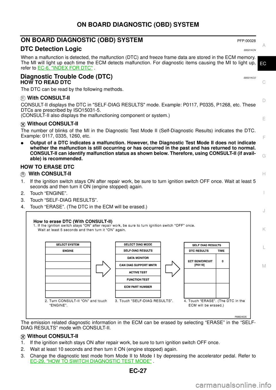
1. If the ignition switch stays ON after repair work, be sure to turn ignition switch OFF once. Wait at least 5
seconds and then turn it ON (engine stopped) again.
2. Touch “ENGINE”.
3. Touch “SELF-DIAG RESULTS”.
4. Touch “ERASE”. (The DTC in the ECM will be erased.)
The emission related diagnostic information in the ECM can be erased by selecting “ERASE” in the “SELF-
DIAG RESULTS” mode with CONSULT-II.
Without CONSULT-II
1. If the ignition switch stays ON after repair work, be sure to turn ignition switch OFF once.
2. Wait at least 10 seconds and then turn it ON (engine stopped) again.
3. Change the diagnostic test mode from Mode II to Mode I by depressing the accelerator pedal. Refer to
EC-29, "
HOW TO SWITCH DIAGNOSTIC TEST MODE".
PBIB2452E
Page 1008 of 3171
EC-28
ON BOARD DIAGNOSTIC (OBD) SYSTEM
lIf the battery is disconnected, the emission-related diagnostic information will be lost within 24
hours.
lThe following data are cleared when the ECM memory is erased.
–Diagnostic trouble codes
–Freeze frame data
–Fuel pump learning value
Actual work procedures are explained using a DTC as an example. Be careful so that not only the DTC, but all
of the data listed above, are cleared from the ECM memory during work procedures.
Freeze Frame DataEBS01KCP
The ECM records the driving conditions such as calculated load value, engine coolant temperature, engine
speed, vehicle speed and intake manifold pressure at the moment a malfunction is detected.
The data, stored together with the DTC data, are called freeze frame data and displayed on CONSULT-II. For
details, seeEC-28, "
Freeze Frame Data".
Only one set of freeze frame data can be stored in the ECM. If freeze frame data is stored in the ECM memory
and another freeze frame data occurs later, the first (original) freeze frame data remains unchanged in the
ECM memory.
Freeze frame data (along with the DTCs) are cleared when the ECM memory is erased. Procedures for clear-
ing the ECM memory are described inEC-27, "
HOW TO ERASE DTC".
NATS (Nissan Anti-theft System)EBS01KCQ
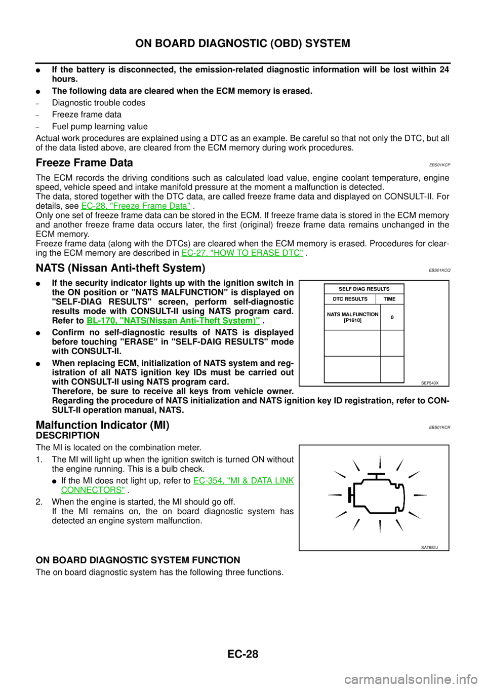
lIf the security indicator lights up with the ignition switch in
the ON position or "NATS MALFUNCTION" is displayed on
"SELF-DIAG RESULTS" screen, perform self-diagnostic
results mode with CONSULT-II using NATS program card.
Refer toBL-170, "
NATS(Nissan Anti-Theft System)".
lConfirm no self-diagnostic results of NATS is displayed
before touching "ERASE" in "SELF-DAIG RESULTS" mode
with CONSULT-II.
lWhen replacing ECM, initialization of NATS system and reg-
istration of all NATS ignition key IDs must be carried out
with CONSULT-II using NATS program card.
Therefore, be sure to receive all keys from vehicle owner.
Regarding the procedure of NATS initialization and NATS ignition key ID registration, refer to CON-
SULT-II operation manual, NATS.
Malfunction Indicator (MI)EBS01KCR
DESCRIPTION
The MI is located on the combination meter.
1. The MI will light up when the ignition switch is turned ON without
the engine running. This is a bulb check.
lIf the MI does not light up, refer toEC-354, "MI&DATA LINK
CONNECTORS".
2. When the engine is started, the MI should go off.
If the MI remains on, the on board diagnostic system has
detected an engine system malfunction.
ON BOARD DIAGNOSTIC SYSTEM FUNCTION
The on board diagnostic system has the following three functions.
SEF543X
SAT652J
Page 1009 of 3171
ON BOARD DIAGNOSTIC (OBD) SYSTEM
EC-29
C
D
E
F
G
H
I
J
K
L
MA
EC
HOWTOSWITCHDIAGNOSTICTESTMODE
NOTE:
lIt is better to count the time accurately with a clock.
lIt is impossible to switch the diagnostic mode when an accelerator pedal position sensor circuit
has a malfunction.
lAlways ECM returns to Diagnostic Test Mode I after ignition switch is turned OFF.
How to Set Diagnostic Test Mode II (Self-diagnostic Results)
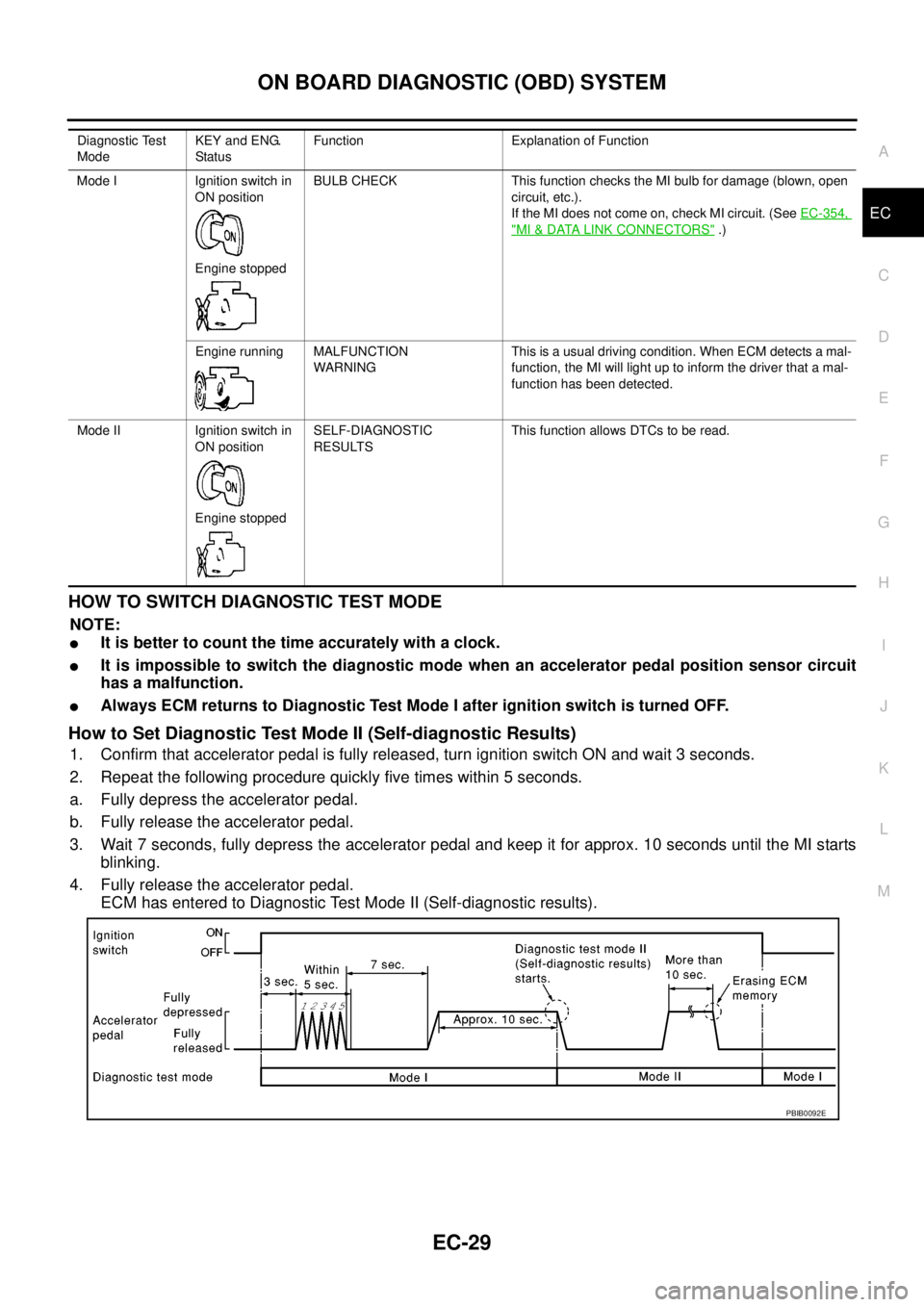
1. Confirm that accelerator pedal is fully released, turn ignition switch ON and wait 3 seconds.
2. Repeat the following procedure quickly five times within 5 seconds.
a. Fully depress the accelerator pedal.
b. Fully release the accelerator pedal.
3. Wait 7 seconds, fully depress the accelerator pedal and keep it for approx. 10 seconds until the MI starts
blinking.
4. Fully release the accelerator pedal.
ECM has entered to Diagnostic Test Mode II (Self-diagnostic results).
Diagnostic Test
ModeKEY and ENG.
Statu sFunction Explanation of Function
Mode I Ignition switch in
ON position
Engine stoppedBULB CHECK This function checks the MI bulb for damage (blown, open
circuit, etc.).
If the MI does not come on, check MI circuit. (SeeEC-354,
"MI&DATA LINK CONNECTORS".)
Engine running MALFUNCTION
WARNINGThis is a usual driving condition. When ECM detects a mal-
function, the MI will light up to inform the driver that a mal-
function has been detected.
Mode II Ignition switch in
ON position
Engine stoppedSELF-DIAGNOSTIC
RESULTSThis function allows DTCs to be read.
PBIB0092E
Page 1010 of 3171
EC-30
ON BOARD DIAGNOSTIC (OBD) SYSTEM
How to Erase Diagnostic Test Mode II (Self-diagnostic Results)
1. Set ECM in Diagnostic Test Mode II (Self-diagnostic results). Refer toEC-29, "How to Set Diagnostic Test
Mode II (Self-diagnostic Results)".
2. Fully depress the accelerator pedal and keep it for more than 10 seconds.
The emission-related diagnostic information has been erased from the backup memory in the ECM.
3. Fully release the accelerator pedal, and confirm the DTC 0000 is displayed.
DIAGNOSTIC TEST MODE I — BULB CHECK
In this mode, the MI on the combination meter should stay ON. If it remains OFF, check the bulb. Refer toEC-
354, "MI&DATA LINK CONNECTORS".
DIAGNOSTIC TEST MODE I — MALFUNCTION WARNING
These DTC numbers are clarified in Diagnostic Test Mode II (SELF-DIAGNOSTIC RESULTS)
DIAGNOSTIC TEST MODE II — SELF-DIAGNOSTIC RESULTS
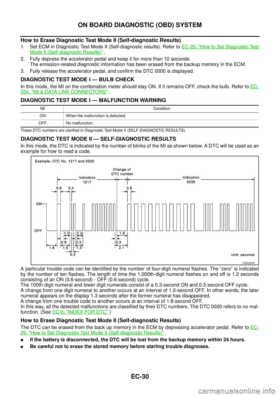
In this mode, the DTC is indicated by the number of blinks of the MI as shown below. A DTC will be used as an
example for how to read a code.
A particular trouble code can be identified by the number of four-digit numeral flashes. The “zero” is indicated
by the number of ten flashes. The length of time the 1,000th-digit numeral flashes on and off is 1.2 seconds
consisting of an ON (0.6-second) - OFF (0.6-second) cycle.
The 100th-digit numeral and lower digit numerals consist of a 0.3-second ON and 0.3-second OFF cycle.
A change from one digit numeral to another occurs at an interval of 1.0-second OFF. In other words, the later
numeral appears on the display 1.3 seconds after the former numeral has disappeared.
A change from one trouble code to another occurs at an interval of 1.8-second OFF.
In this way, all the detected malfunctions are classified by their DTC numbers. The DTC 0000 refers to no mal-
function. (SeeEC-6, "
INDEX FOR DTC")
How to Erase Diagnostic Test Mode II (Self-diagnostic Results)
The DTC can be erased from the back up memory in the ECM by depressing accelerator pedal. Refer toEC-
29, "How to Set Diagnostic Test Mode II (Self-diagnostic Results)".
lIf the battery is disconnected, the DTC will be lost from the backup memory within 24 hours.
lBe careful not to erase the stored memory before starting trouble diagnoses.
MI Condition
ON When the malfunction is detected.
OFF No malfunction.
PBIA3905E
Page 1042 of 3171

EC-62
TROUBLE DIAGNOSIS
WORK SUPPORT MODE
Work Item
SELF-DIAGNOSTIC MODE
Self Diagnostic Item
Regarding items detected in “SELF-DIAG RESULTS” mode, refer to —EC-6, "INDEX FOR DTC".
Freeze Frame Data
DATA MONITOR MODE
WORK ITEM DESCRIPTION USAGE
ENTER INJCTR CALIB DATA
lInjector adjustment value is written onto ECM memory. When performing Injector Adjust-
ment Value Registration.
CONFIG CLR
lASCD application status stored in ECM is initialized.
NOTE:
After the status is initialized, ECM recognizes ASCD
application status when the following condition is met.
lFor ASCD: ASCD MAIN switch is pressed.When initializing ASCD applica-
tion status stored in ECM.
INJ ADJ VAL CLR
lInjector adjustment value stored in ECM is initialized. Before changing injector adjust-
ment value stored in ECM, it is
recommended to perform this
work item.
Freeze frame data item Description
DIAG TROUBLE CODE
[PXXXX]
lThe engine control component part/control system has a trouble code, it is displayed as “PXXXX”.
(Refer toEC-6, "
INDEX FOR DTC".)
CAL/LD VALUE [%]
lThe calculated load value at the moment a malfunction is detected is displayed.
COOLANT TEMP [°C] or [°F]
lThe engine coolant temperature at the moment a malfunction is detected is displayed.
ENGINE SPEED [rpm]
lThe engine speed at the moment a malfunction is detected is displayed.
VEHICL SPEED
[km/h] or [mph]
lThe vehicle speed at the moment a malfunction is detected is displayed.
INT MANI PRES [kPa]
lThe intake manifold pressure at the moment a malfunction is detected is displayed.
MONITOR ITEMECM
INPUT
SIG-
NALMAIN
SIG-
NALSCONDITION SPECIFICATION
CKPS·RPM (TDC) [rpm]´´
lThe engine speed computed from the
crankshaft position sensor signal is
displayed.
COOLAN TEMP/S
[°C] or [°F]´´
lThe engine coolant temperature
(determined by the signal voltage of
the engine coolant temperature sen-
sor) is displayed.When the engine coolant temperature
circuit is open or short, ECM enters fail-
safe mode. The engine coolant tempera-
ture determined by the ECM is dis-
played.
VHCL SPEED SE
[km/h] or [mph]´´
lThe vehicle speed computed form the
vehicle speed signal is displayed.
FUEL TEMP SEN
[°C] or [°F]´´
lThe fuel temperature (determined by
the signal voltage of the fuel pump
temperature sensor) is displayed.
ACCEL POS SEN [V]´´
lThe accelerator pedal position sensor
1 signal voltage is displayed.This signal is converted by ECM inter-
nally. Thus, these differ from ECM termi-
nals voltage.
ACCEL SEN 2 [V]´´
lThe accelerator pedal position sensor
2 signal voltage is displayed.This signal is converted by ECM inter-
nally. Thus, these differ from ECM termi-
nals voltage.
Page 1045 of 3171
TROUBLE DIAGNOSIS
EC-65
C
D
E
F
G
H
I
J
K
L
MA
EC
*: Leaving cooling fan OFF with CONSULT-II while engine is running may cause the engine to overheat.
REAL TIME DIAGNOSIS IN DATA MONITOR MODE
CONSULT-II has two kinds of triggers and they can be selected by touching “SETTING” in “DATA MONITOR”
mode.
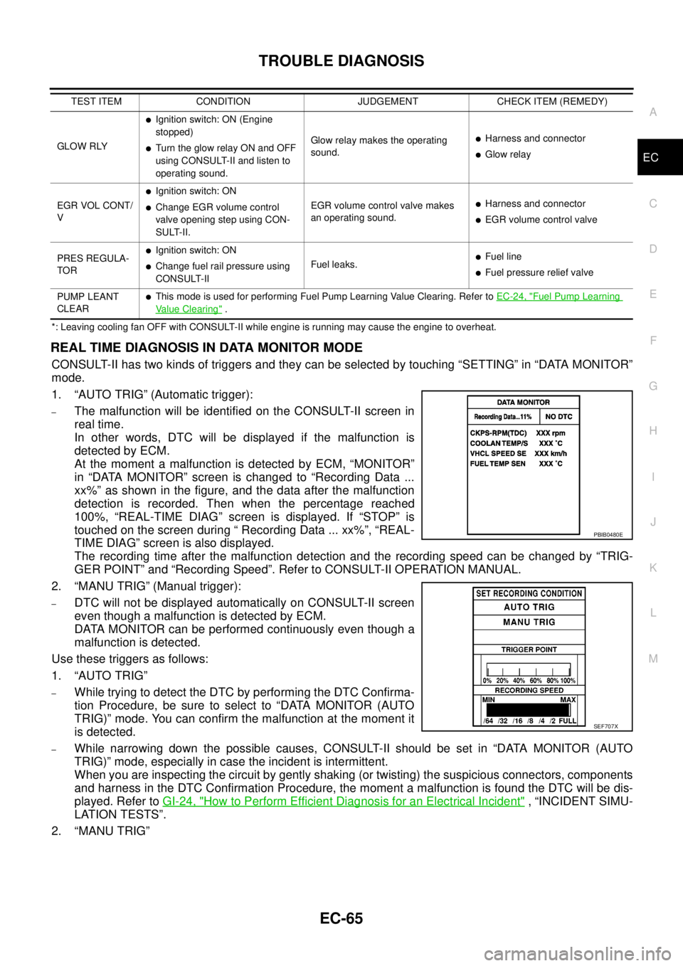
1. “AUTO TRIG” (Automatic trigger):
–The malfunction will be identified on the CONSULT-II screen in
real time.
In other words, DTC will be displayed if the malfunction is
detected by ECM.
At the moment a malfunction is detected by ECM, “MONITOR”
in “DATA MONITOR” screen is changed to “Recording Data ...
xx%” as shown in the figure, and the data after the malfunction
detection is recorded. Then when the percentage reached
100%, “REAL-TIME DIAG” screen is displayed. If “STOP” is
touched on the screen during “ Recording Data ... xx%”, “REAL-
TIME DIAG” screen is also displayed.
The recording time after the malfunction detection and the recording speed can be changed by “TRIG-
GER POINT” and “Recording Speed”. Refer to CONSULT-II OPERATION MANUAL.
2. “MANU TRIG” (Manual trigger):
–DTC will not be displayed automatically on CONSULT-II screen
even though a malfunction is detected by ECM.
DATA MONITOR can be performed continuously even though a
malfunction is detected.
Use these triggers as follows:
1. “AUTO TRIG”
–While trying to detect the DTC by performing the DTC Confirma-
tion Procedure, be sure to select to “DATA MONITOR (AUTO
TRIG)” mode. You can confirm the malfunction at the moment it
is detected.
–While narrowing down the possible causes, CONSULT-II should be set in “DATA MONITOR (AUTO
TRIG)” mode, especially in case the incident is intermittent.
When you are inspecting the circuit by gently shaking (or twisting) the suspicious connectors, components
and harness in the DTC Confirmation Procedure, the moment a malfunction is found the DTC will be dis-
played. Refer toGI-24, "
How to Perform Efficient Diagnosis for an Electrical Incident", “INCIDENT SIMU-
LATION TESTS”.
2. “MANU TRIG”
GLOW RLY
lIgnition switch: ON (Engine
stopped)
lTurn the glow relay ON and OFF
using CONSULT-II and listen to
operating sound.Glow relay makes the operating
sound.lHarness and connector
lGlow relay
EGR VOL CONT/
V
lIgnition switch: ON
lChange EGR volume control
valve opening step using CON-
SULT-II.EGR volume control valve makes
an operating sound.lHarness and connector
lEGR volume control valve
PRES REGULA-
TOR
lIgnition switch: ON
lChange fuel rail pressure using
CONSULT-IIFuel leaks.lFuel line
lFuel pressure relief valve
PUMP LEANT
CLEAR
lThis mode is used for performing Fuel Pump Learning Value Clearing. Refer toEC-24, "Fuel Pump Learning
Value Clearing". TEST ITEM CONDITION JUDGEMENT CHECK ITEM (REMEDY)
PBIB0480E
SEF707X
Page 1059 of 3171
DTC U1000 CAN COMMUNICATION LINE
EC-79
C
D
E
F
G
H
I
J
K
L
MA
EC
DTC U1000 CAN COMMUNICATION LINEPFP:23710
DescriptionEBS01KDA
CAN (Controller Area Network) is a serial communication line for real time application. It is an on-vehicle mul-
tiplex communication line with high data communication speed and excellent error detection ability. Many elec-
tronic control units are equipped onto a vehicle, and each control unit shares information and links with other
control units during operation (not independent). In CAN communication, control units are connected with 2
communication lines (CAN H line, CAN L line) allowing a high rate of information transmission with less wiring.
Each control unit transmits/receives data but selectively reads required data only.
On Board Diagnosis LogicEBS01KDB
The MI will not light up for this self-diagnosis.
DTC Confirmation ProcedureEBS01KDC
NOTE:
If DTC Confirmation Procedure has been previously conducted, always turn ignition switch OFF and wait at
least 10 seconds before conducting the next test.
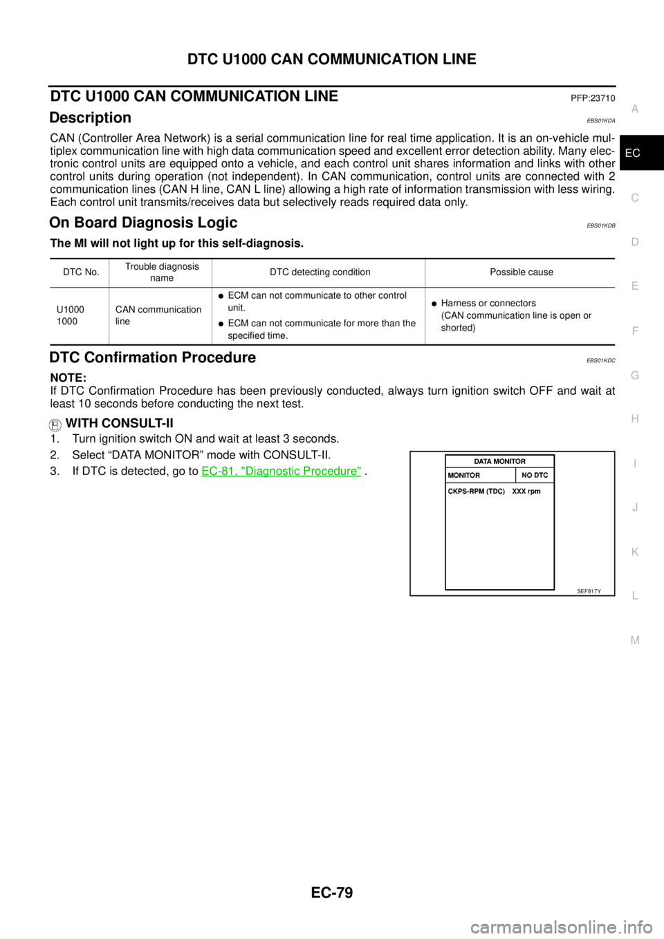
WITH CONSULT-II
1. Turn ignition switch ON and wait at least 3 seconds.
2. Select “DATA MONITOR” mode with CONSULT-II.
3. If DTC is detected, go toEC-81, "
Diagnostic Procedure".
DTC No.Trouble diagnosis
nameDTC detecting condition Possible cause
U1000
1000CAN communication
line
lECM can not communicate to other control
unit.
lECM can not communicate for more than the
specified time.
lHarness or connectors
(CAN communication line is open or
shorted)
SEF817Y