2005 NISSAN NAVARA ECO mode
[x] Cancel search: ECO modePage 205 of 3171
TROUBLE DIAGNOSIS FOR SYMPTOMS
AT-197
D
E
F
G
H
I
J
K
L
MA
B
AT
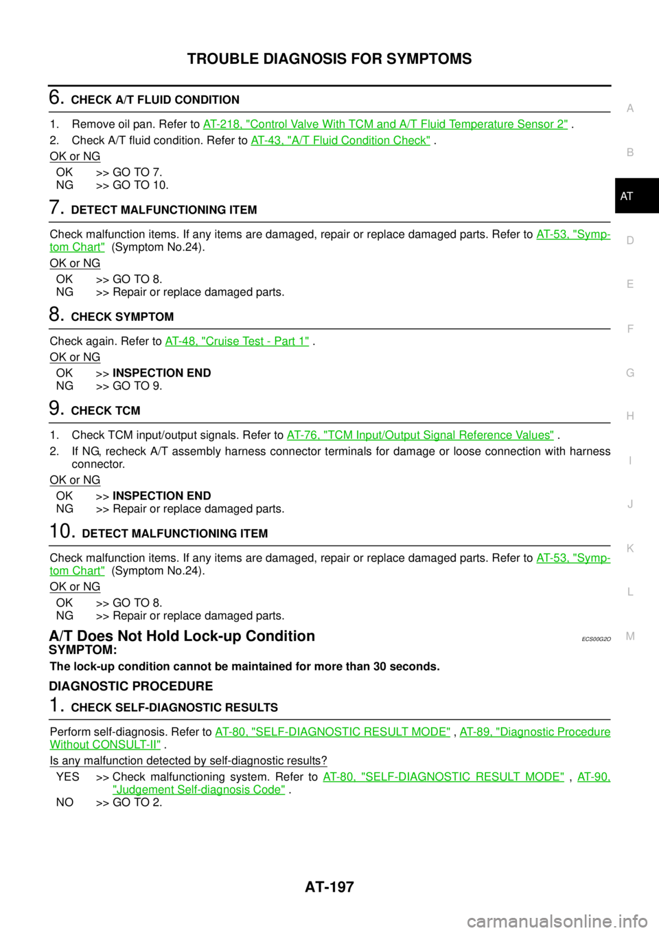
6.CHECK A/T FLUID CONDITION
1. Remove oil pan. Refer toAT- 2 1 8 , "
Control Valve With TCM and A/T Fluid Temperature Sensor 2".
2. Check A/T fluid condition. Refer toAT-43, "
A/T Fluid Condition Check".
OK or NG
OK >> GO TO 7.
NG >> GO TO 10.
7.DETECT MALFUNCTIONING ITEM
Check malfunction items. If any items are damaged, repair or replace damaged parts. Refer toAT-53, "
Symp-
tom Chart"(Symptom No.24).
OK or NG
OK >> GO TO 8.
NG >> Repair or replace damaged parts.
8.CHECK SYMPTOM
Check again. Refer toAT-48, "
Cruise Test - Part 1".
OK or NG
OK >>INSPECTION END
NG >> GO TO 9.
9.CHECK TCM
1. Check TCM input/output signals. Refer toAT-76, "
TCM Input/Output Signal Reference Values".
2. If NG, recheck A/T assembly harness connector terminals for damage or loose connection with harness
connector.
OK or NG
OK >>INSPECTION END
NG >> Repair or replace damaged parts.
10.DETECT MALFUNCTIONING ITEM
Check malfunction items. If any items are damaged, repair or replace damaged parts. Refer toAT-53, "
Symp-
tom Chart"(Symptom No.24).
OK or NG
OK >> GO TO 8.
NG >> Repair or replace damaged parts.
A/T Does Not Hold Lock-up ConditionECS00G2O
SYMPTOM:
The lock-up condition cannot be maintained for more than 30 seconds.
DIAGNOSTIC PROCEDURE
1.CHECK SELF-DIAGNOSTIC RESULTS
Perform self-diagnosis. Refer toAT-80, "
SELF-DIAGNOSTIC RESULT MODE",AT-89, "Diagnostic Procedure
Without CONSULT-II".
Is any malfunction detected by self-diagnostic results?
YES >> Check malfunctioning system. Refer toAT-80, "SELF-DIAGNOSTIC RESULT MODE",AT- 9 0 ,
"Judgement Self-diagnosis Code".
NO >> GO TO 2.
Page 331 of 3171
SERVICE DATA AND SPECIFICATIONS (SDS)
AT-323
D
E
F
G
H
I
J
K
L
MA
B
AT
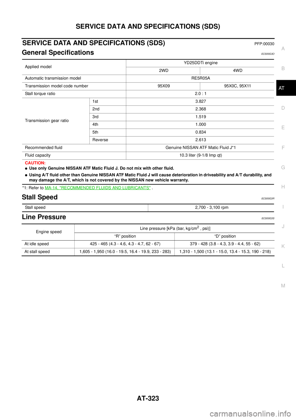
SERVICE DATA AND SPECIFICATIONS (SDS)PFP:00030
General SpecificationsECS00G3O
*1: Refer toMA-14, "RECOMMENDED FLUIDS AND LUBRICANTS".
Stall SpeedECS00G3R
Line PressureECS00G3S
Applied modelYD25DDTi engine
2WD 4WD
Automatic transmission model RE5R05A
Transmission model code number 95X09 95X0C, 95X11
Stall torque ratio2.0 : 1
Transmission gear ratio1st 3.827
2nd 2.368
3rd 1.519
4th 1.000
5th 0.834
Reverse 2.613
Recommended fluid Genuine NISSAN ATF Matic Fluid J*1
Fluid capacity 10.3 liter (9-1/8 Imp qt)
CAUTION:
lUse only Genuine NISSAN ATF Matic Fluid J. Do not mix with other fluid.
lUsing A/T fluid other than Genuine NISSAN ATF Matic Fluid J will cause deterioration in driveability and A/T durability, and
may damage the A/T, which is not covered by the NISSAN new vehicle warranty.
Stall speed2,700 - 3,100 rpm
Engine speedLine pressure [kPa (bar, kg/cm2,psi)]
“R” position “D” position
At idle speed 425 - 465 (4.3 - 4.6, 4.3 - 4.7, 62 - 67) 379 - 428 (3.8 - 4.3, 3.9 - 4.4, 55 - 62)
At stall speed 1,605 - 1,950 (16.0 - 19.5, 16.4 - 19.9, 233 - 283) 1,310 - 1,500 (13.1 - 15.0, 13.4 - 15.3, 190 - 218)
Page 335 of 3171

ATC-1
AUTOMATIC AIR CONDITIONER
J AIR CONDITIONER
CONTENTS
C
D
E
F
G
H
I
K
L
M
SECTIONAT C
A
B
AT C
AUTOMATIC AIR CONDITIONER
PRECAUTIONS .......................................................... 4
Precautions for Supplemental Restraint System
(SRS)“AIRBAG”and“SEATBELTPRE-TEN-
SIONER” .................................................................. 4
Precautions for Working with HFC-134a (R-134a)..... 4
Contaminated Refrigerant ........................................ 4
General Refrigerant Precautions .............................. 5
Precautions for Refrigerant Connection ................... 5
ABOUT ONE-TOUCH JOINT ................................ 5
FEATURES OF NEW TYPE REFRIGERANT
CONNECTION ...................................................... 7
O-RING AND REFRIGERANT CONNECTION..... 9
Precautions for Servicing Compressor ................... 12
Precautions for Service Equipment ........................ 12
RECOVERY/RECYCLING EQUIPMENT ............ 12
ELECTRONIC LEAK DETECTOR ...................... 12
VACUUM PUMP ................................................. 13
MANIFOLD GAUGE SET .................................... 13
SERVICE HOSES ............................................... 13
SERVICE COUPLERS ........................................ 14
REFRIGERANT WEIGHT SCALE ...................... 14
CALIBRATING ACR4 WEIGHT SCALE .............. 14
CHARGING CYLINDER ...................................... 14
Precautions for Leak Detection Dye ....................... 14
IDENTIFICATION ................................................ 15
IDENTIFICATION LABEL FOR VEHICLE ........... 15
Wiring Diagrams and Trouble Diagnosis ................ 15
PREPARATION ......................................................... 16
Special Service Tools ............................................. 16
HFC-134a (R-134a) Service Tools and Equipment... 16
Commercial Service Tools ...................................... 19
REFRIGERATION SYSTEM ..................................... 20
Refrigerant Cycle ................................................... 20
REFRIGERANT FLOW ....................................... 20
FREEZE PROTECTION ..................................... 20
Refrigerant System Protection ............................... 20
REFRIGERANT PRESSURE SENSOR ............. 20
PRESSURE RELIEF VALVE ............................... 21
Components ........................................................... 22
REFRIGERATION SYSTEM ............................... 22LUBRICANT .............................................................. 24
Maintenance of Lubricant Quantity in Compressor... 24
LUBRICANT ........................................................ 24
CHECKING AND ADJUSTING ............................ 24
AIR CONDITIONER CONTROL ............................... 26
Description .............................................................. 26
Operation ................................................................ 26
AIR MIX DOORS CONTROL .............................. 26
BLOWER SPEED CONTROL ............................. 26
INTAKE DOOR CONTROL ................................. 26
MODE DOOR CONTROL ................................... 26
DEFROSTER DOOR CONTROL ........................ 26
MAGNET CLUTCH CONTROL ........................... 27
SELF-DIAGNOSTIC SYSTEM ............................ 27
Description of Control System ................................ 28
Control Operation ................................................... 28
DISPLAY SCREEN .............................................. 29
AUTO SWITCH ................................................... 29
TEMPERATURE CONTROL DIAL (TEMPERA-
TURE CONTROL) (DRIVER SIDE) ..................... 29
TEMPERATURE CONTROL DIAL (TEMPERA-
TURE CONTROL) (PASSENGER SIDE) ............ 29
TEMPERATURE CONTROL DIAL (TEMPERA-
TURE AND MODE CONTROL) (REAR) ............. 29
RECIRCULATION (REC) SWITCH ..................... 29
DEFROSTER (DEF) SWITCH ............................. 29
REAR WINDOW DEFOGGER SWITCH ............. 29
OFF SWITCH ...................................................... 29
A/C SWITCH ....................................................... 29
MODE SWITCH (FRONT) ................................... 29
FRONT BLOWER CONTROL DIAL .................... 29
MODE SWITCH (REAR) ..................................... 29
Discharge Air Flow ................................................. 30
FRONT ................................................................ 30
System Description ................................................. 31
SWITCHES AND THEIR CONTROL FUNCTION... 31
CAN Communication System Description .............. 32
TROUBLE DIAGNOSIS ............................................ 33
CONSULT-II Function (BCM) ................................. 33
CONSULT-II BASIC OPERATION ....................... 33
Page 348 of 3171

ATC-14
PRECAUTIONS
SERVICE COUPLERS
Never attempt to connect HFC-134a (R-134a) service couplers to an
CFC-12 (R-12) A/C system. The HFC-134a (R-134a) couplers will
not properly connect to the CFC-12 (R-12) system. However, if an
improper connection is attempted, discharging and contamination
may occur.
REFRIGERANT WEIGHT SCALE
Verify that no refrigerant other than HFC-134a (R-134a) and speci-
fied lubricants have been used with the scale. If the scale controls
refrigerant flow electronically, the hose fitting must be 1/2²-16
ACME.
CALIBRATING ACR4 WEIGHT SCALE
Calibrate the scale every three months.
To calibrate the weight scale on the ACR4:
1. Press “Shift/Reset”and“Enter”at the same time.
2. Press “8787”.“A1” will be displayed.
3. Remove all weight from the scale.
4. Press “0”, then press “Enter”.“0.00” will be displayed and change to “A2”.
5. Place a known weight (dumbbell or similar weight), between 4.5 and 8.6 kg (10 and 19 lb.) on the center
of the weight scale.
6. Enter the known weight using four digits. (Example 10 lb. = 10.00, 10.5 lb. = 10.50)
7. Press “Enter”— the display returns to the vacuum mode.
8. Press“Shift/Reset”and“Enter”at the same time.
9. Press “6” — the known weight on the scale is displayed.
10. Remove the known weight from the scale. “0.00” will be displayed.
11. Press“Shift/Reset” to return the ACR4 to the program mode.
CHARGING CYLINDER
Using a charging cylinder is not recommended. Refrigerant may be vented into air from cylinder’s top valve
when filling the cylinder with refrigerant. Also, the accuracy of the cylinder is generally less than that of an
electronic scale or of quality recycle/recharge equipment.
Precautions for Leak Detection DyeEJS006AR
lThe A/C system contains a fluorescent leak detection dye used for locating refrigerant leaks. An ultraviolet
(UV) lamp is required to illuminate the dye when inspecting for leaks.
lAlways wear fluorescence enhancing UV safety goggles to protect your eyes and enhance the visibility of
the fluorescent dye.
lThe fluorescent dye leak detector is not a replacement for an electronic refrigerant leak detector. The fluo-
rescent dye leak detector should be used in conjunction with an electronic refrigerant leak detector (J-
41995) to pin-point refrigerant leaks.
lFor your safety and your customer’s satisfaction, read and follow all manufacture’s operating instructions
and precautions prior to performing the work.
Shut-off valve rotation A/C service valve
Clockwise Open
Counterclockwise Close
RHA273D
RHA274D
Page 368 of 3171
ATC-34
TROUBLE DIAGNOSIS
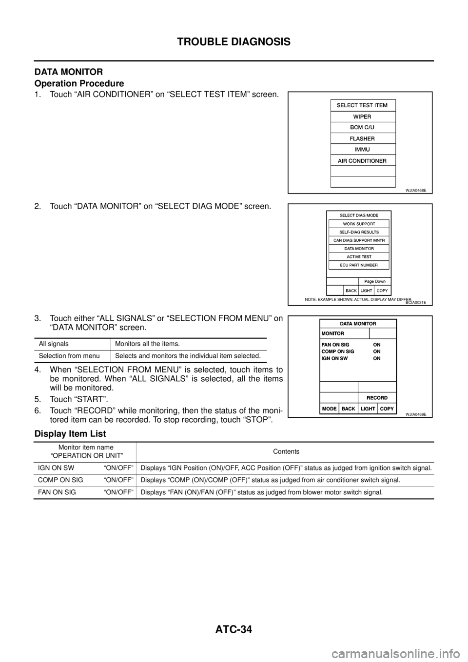
DATA MONITOR
Operation Procedure
1. Touch “AIR CONDITIONER” on “SELECT TEST ITEM” screen.
2. Touch “DATA MONITOR” on “SELECT DIAG MODE” screen.
3. Touch either “ALL SIGNALS” or “SELECTION FROM MENU” on
“DATA MONITOR” screen.
4. When “SELECTION FROM MENU” is selected, touch items to
be monitored. When “ALL SIGNALS” is selected, all the items
will be monitored.
5. Touch “START”.
6. Touch “RECORD” while monitoring, then the status of the moni-
tored item can be recorded. To stop recording, touch “STOP”.
Display Item List
WJIA0468E
BCIA0031E
All signals Monitors all the items.
Selection from menu Selects and monitors the individual item selected.
WJIA0469E
Monitor item name
“OPERATION OR UNIT”Contents
IGN ON SW “ON/OFF” Displays “IGN Position (ON)/OFF, ACC Position (OFF)” status as judged from ignition switch signal.
COMP ON SIG “ON/OFF” Displays “COMP (ON)/COMP (OFF)” status as judged from air conditioner switch signal.
FAN ON SIG “ON/OFF” Displays “FAN (ON)/FAN (OFF)” status as judged from blower motor switch signal.
Page 401 of 3171
TROUBLE DIAGNOSIS
ATC-67
C
D
E
F
G
H
I
K
L
MA
B
AT C
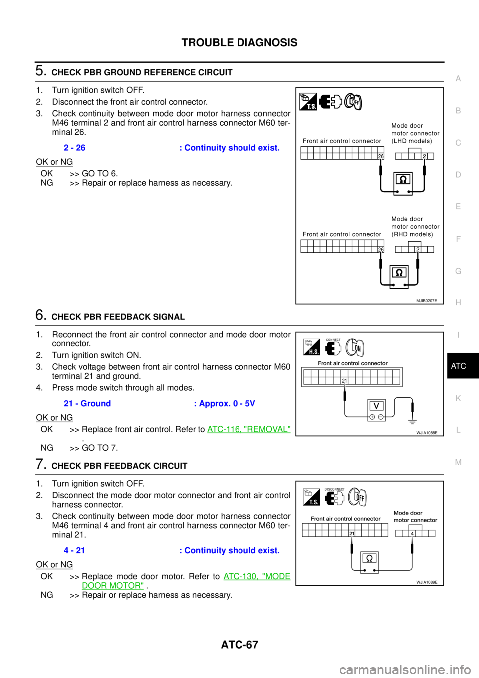
5.CHECK PBR GROUND REFERENCE CIRCUIT
1. Turn ignition switch OFF.
2. Disconnect the front air control connector.
3. Check continuity between mode door motor harness connector
M46 terminal 2 and front air control harness connector M60 ter-
minal 26.
OK or NG
OK >> GO TO 6.
NG >> Repair or replace harness as necessary.
6.CHECK PBR FEEDBACK SIGNAL
1. Reconnect the front air control connector and mode door motor
connector.
2. Turn ignition switch ON.
3. Check voltage between front air control harness connector M60
terminal 21 and ground.
4. Press mode switch through all modes.
OK or NG
OK >> Replace front air control. Refer toAT C - 11 6 , "REMOVAL"
.
NG >> GO TO 7.
7.CHECK PBR FEEDBACK CIRCUIT
1. Turn ignition switch OFF.
2. Disconnect the mode door motor connector and front air control
harness connector.
3. Check continuity between mode door motor harness connector
M46 terminal 4 and front air control harness connector M60 ter-
minal 21.
OK or NG
OK >> Replace mode door motor. Refer toATC-130, "MODE
DOOR MOTOR".
NG >> Repair or replace harness as necessary.2 - 26 : Continuity should exist.
MJIB0207E
21 - Ground : Approx. 0 - 5V
WJIA1088E
4 - 21 : Continuity should exist.
WJIA1089E
Page 415 of 3171
TROUBLE DIAGNOSIS
ATC-81
C
D
E
F
G
H
I
K
L
MA
B
AT C
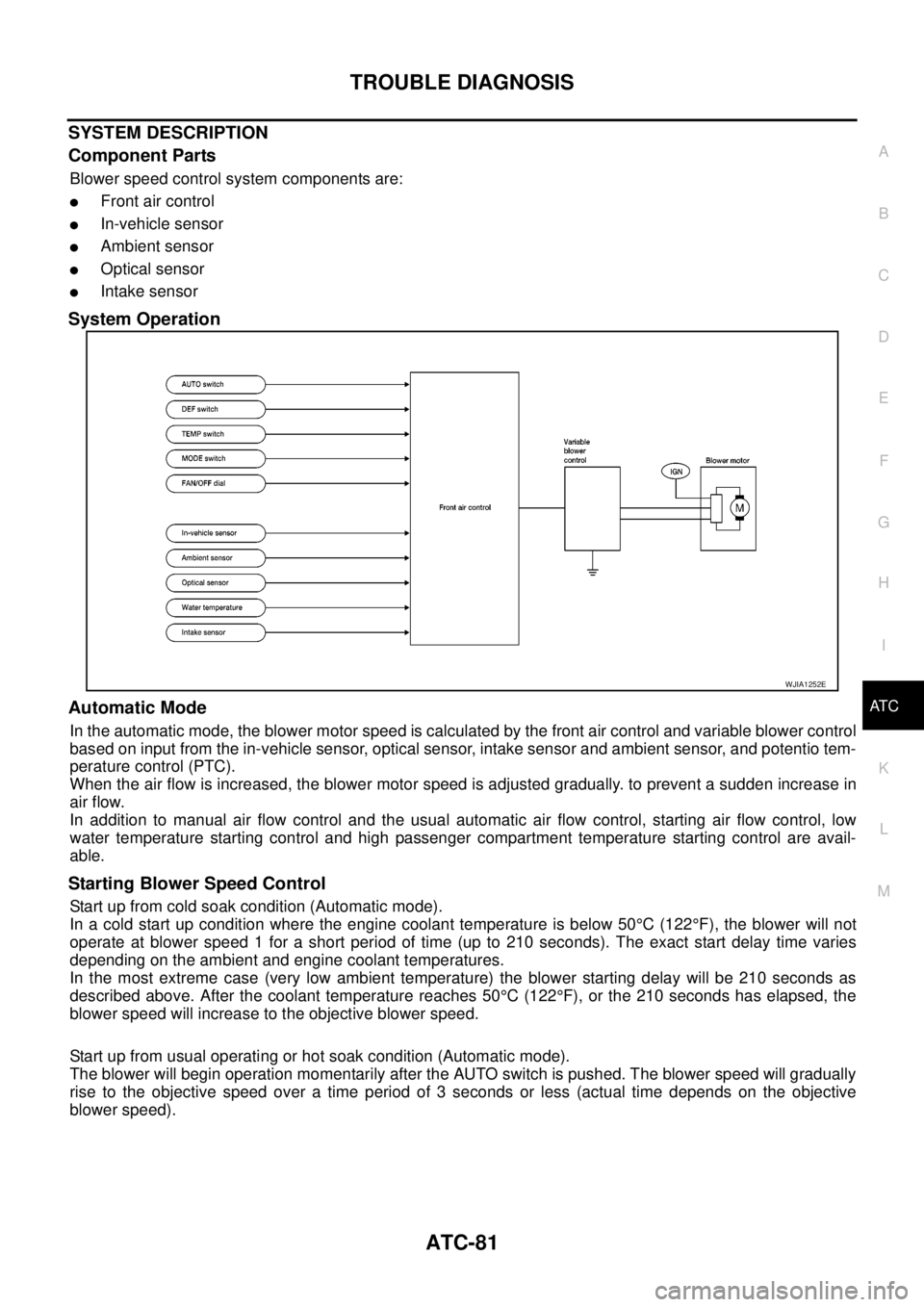
SYSTEM DESCRIPTION
Component Parts
Blower speed control system components are:
lFront air control
lIn-vehicle sensor
lAmbient sensor
lOptical sensor
lIntake sensor
System Operation
Automatic Mode
In the automatic mode, the blower motor speed is calculated by the front air control and variable blower control
based on input from the in-vehicle sensor, optical sensor, intake sensor and ambient sensor, and potentio tem-
perature control (PTC).
When the air flow is increased, the blower motor speed is adjusted gradually. to prevent a sudden increase in
air flow.
In addition to manual air flow control and the usual automatic air flow control, starting air flow control, low
water temperature starting control and high passenger compartment temperature starting control are avail-
able.
Starting Blower Speed Control
Start up from cold soak condition (Automatic mode).
In a cold start up condition where the engine coolant temperature is below 50°C(122°F), the blower will not
operate at blower speed 1 for a short period of time (up to 210 seconds). The exact start delay time varies
depending on the ambient and engine coolant temperatures.
In the most extreme case (very low ambient temperature) the blower starting delay will be 210 seconds as
described above. After the coolant temperature reaches 50°C(122°F), or the 210 seconds has elapsed, the
blower speed will increase to the objective blower speed.
Start up from usual operating or hot soak condition (Automatic mode).
The blower will begin operation momentarily after the AUTO switch is pushed. The blower speed will gradually
rise to the objective speed over a time period of 3 seconds or less (actual time depends on the objective
blower speed).
WJIA1252E
Page 456 of 3171
ATC-122
AIR CONDITIONER FILTER
AIR CONDITIONER FILTER
PFP:27277
Removal and InstallationEJS006C7
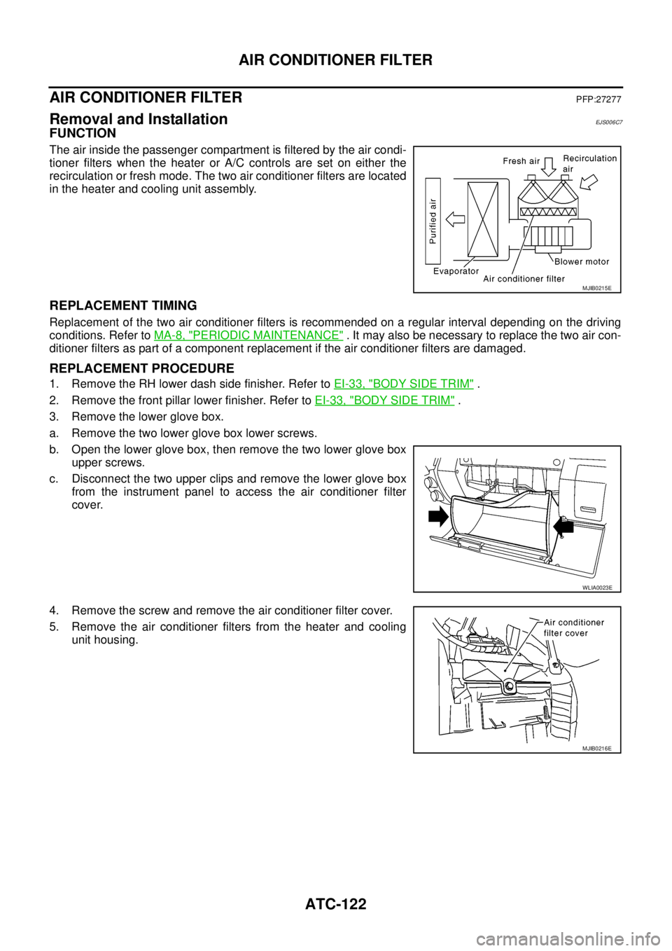
FUNCTION
The air inside the passenger compartment is filtered by the air condi-
tioner filters when the heater or A/C controls are set on either the
recirculation or fresh mode. The two air conditioner filters are located
in the heater and cooling unit assembly.
REPLACEMENT TIMING
Replacement of the two air conditioner filters is recommended on a regular interval depending on the driving
conditions. Refer toMA-8, "
PERIODIC MAINTENANCE". It may also be necessary to replace the two air con-
ditioner filters as part of a component replacement if the air conditioner filters are damaged.
REPLACEMENT PROCEDURE
1. Remove the RH lower dash side finisher. Refer toEI-33, "BODY SIDE TRIM".
2. Remove the front pillar lower finisher. Refer toEI-33, "
BODY SIDE TRIM".
3. Remove the lower glove box.
a. Remove the two lower glove box lower screws.
b. Open the lower glove box, then remove the two lower glove box
upper screws.
c. Disconnect the two upper clips and remove the lower glove box
from the instrument panel to access the air conditioner filter
cover.
4. Remove the screw and remove the air conditioner filter cover.
5. Remove the air conditioner filters from the heater and cooling
unit housing.
MJIB0215E
WLIA0023E
MJIB0216E