2005 NISSAN NAVARA ECO mode
[x] Cancel search: ECO modePage 676 of 3171

BL-92
MULTI-REMOTE CONTROL SYSTEM
Auto Re-lock Function
The BCM is equipped with an auto re-lock function, when no further user action occurs after an full or partial
unlock, the doors will automatically re-lock after 2 minutes (default value).
The auto re-lock function will not be activated under the following state.
lKeyswitchisOn
lMechanical key is inserted
lAny door is opened
NOTE:
The 2 minutes timer of auto re-lock will be reset if unlock button from the key fob is pressed.
Auto relock function can be changed using “WORK SUPPORT” mode in “AUTO LOCK SET”.
Refer toBL-104, "
Work Support".
Room Lamp Operation
When the following conditions are met:
lcondition of room lamp switch is DOOR position;
ldoor switch OFF (when all the doors are closed);
With input of UNLOCK signal from keyfob multi-remote control system turns on interior lamp (for 30 seconds).
CAN Communication System DescriptionEIS00DBF
Refer toLAN-23, "CAN COMMUNICATION".
Page 690 of 3171

BL-106
MULTI-REMOTE CONTROL SYSTEM
Check Keyfob Battery and Function
EIS00DBO
1.CHECK KEYFOB BATTERY
1. Remove keyfob battery. Refer toBL-116, "
Remote Controller Battery Replacement".
2. Measure voltage between battery positive and negative termi-
nals, (+) and (-).
NOTE:
Keyfob does not function if battery is not set correctly.
OK or NG
OK >> GO TO 2.
NG >> Replace battery.
2.CHECK KEYFOB FUNCTION
With CONSULT-II
Check keyfob function in “DATA MONITOR” mode with CONSULT-II. When pushing each button of keyfob, the
corresponding monitor item should be turned as follows.
OK or NG
OK >> Keyfob is OK.
NG >> Replace keyfob.Voltage : 2.5 – 3.0V
SEL237W
Condition Monitor item
Pushing LOCK KEYLESS LOCK : ON
Pushing UNLOCK KEYLESS UNLOCK : ON
Press and hold UNLOCKRKE KEEP UNLK* : ON
*: Press and hold the unlock button for 3
seconds.
Pushing LOCK and UNLOCK at the
same timeRKE LCK-UNLOCK : ON
PIIA6468E
Page 742 of 3171

BL-158
THEFT WARNING SYSTEM
Active Test
Work Support
KEY CYL LK-SW This is displayed even when it is not equipped.
KEY CYL UN-SW This is displayed even when it is not equipped.
CDL LOCK SW Indicates [ON/OFF] condition of lock signal from door lock/unlock switch LH and RH.
CDL UNLOCK SW Indicates [ON/OFF] condition of unlock signal from door lock/unlock switch LH and RH.
AUTO RELOCK This is displayed even when it is not equipped.
GLS BREAK SEN This is displayed even when it is not equipped.Monitored Item Description
Test Item Description
THEFT INDThis test is able to check security indicator lamp operation. The lamp will be turned on when “ON”
on CONSULT-II screen is touched.
FLASHERThis test is able to check theft warning turn signal lamp operation. The turn signal lamp will be
activated on when “ON” on CONSULT-II screen is touched.
VEHICLE SECURITY HORNThis test is able to check theft warning alarm operation. The horns will be activated for 0.5 sec-
onds after “ON” on CONSULT-II screen is touched.
Test Item Description
SECURITY ALARM SET This mode can confirm and change theft warning alarm ON-OFF setting.
THEFT ALM TRGThe switch which triggered theft warning alarm is recorded. This mode is able to confirm and
erase the record of theft warning alarm. The trigger data can be erased by touching “CLEAR” on
CONSULT-II screen.
Page 756 of 3171

BL-172
NATS(NISSAN ANTI-THEFT SYSTEM)
System Composition
EIS00DAQ
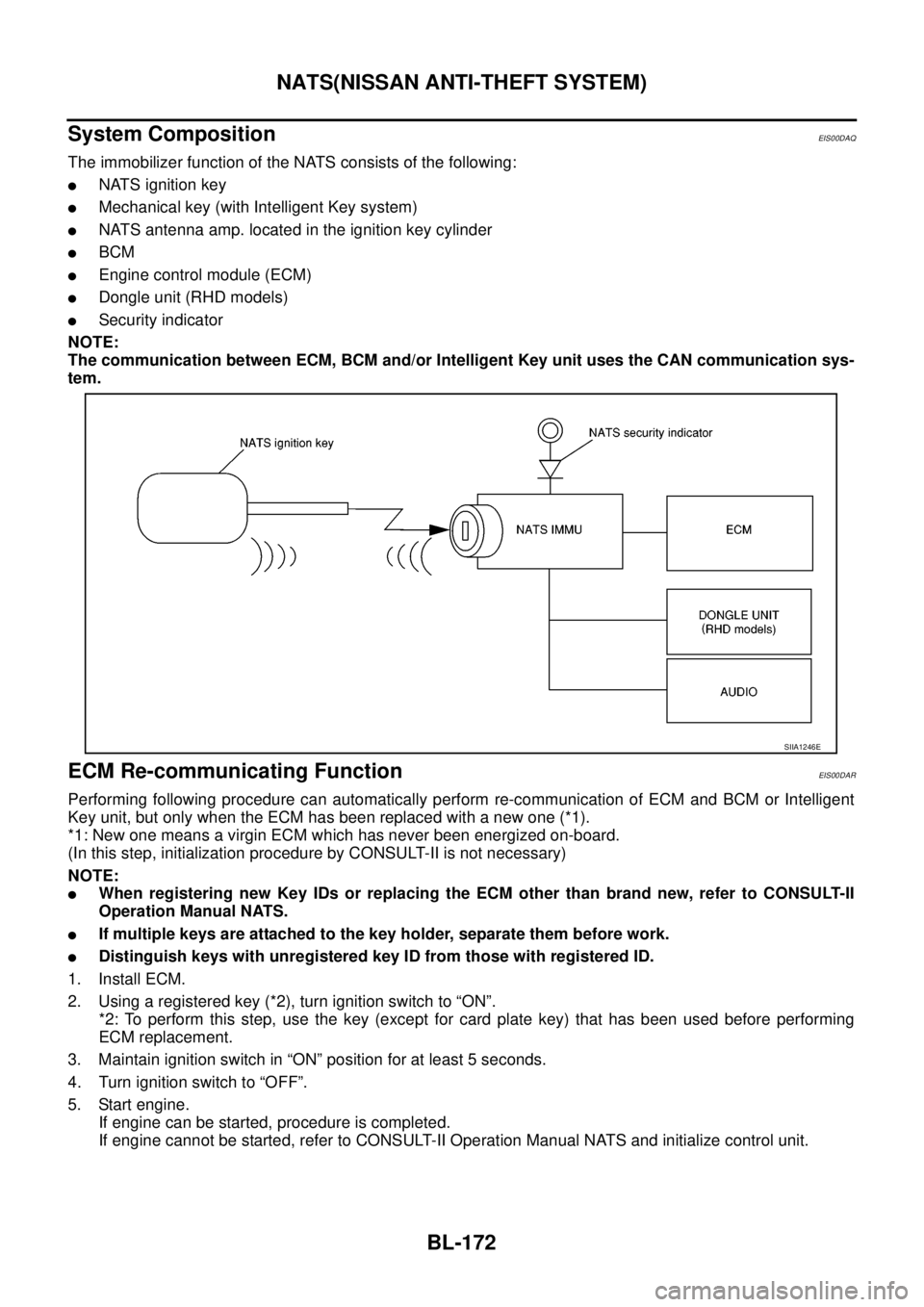
The immobilizer function of the NATS consists of the following:
lNATS ignition key
lMechanical key (with Intelligent Key system)
lNATS antenna amp. located in the ignition key cylinder
lBCM
lEngine control module (ECM)
lDongle unit (RHD models)
lSecurity indicator
NOTE:
The communication between ECM, BCM and/or Intelligent Key unit uses the CAN communication sys-
tem.
ECM Re-communicating FunctionEIS00DAR
Performing following procedure can automatically perform re-communication of ECM and BCM or Intelligent
Key unit, but only when the ECM has been replaced with a new one (*1).
*1: New one means a virgin ECM which has never been energized on-board.
(In this step, initialization procedure by CONSULT-II is not necessary)
NOTE:
lWhen registering new Key IDs or replacing the ECM other than brand new, refer to CONSULT-II
Operation Manual NATS.
lIf multiple keys are attached to the key holder, separate them before work.
lDistinguish keys with unregistered key ID from those with registered ID.
1. Install ECM.
2. Usingaregisteredkey(*2),turnignitionswitchto“ON”.
*2: To perform this step, use the key (except for card plate key) that has been used before performing
ECM replacement.
3. Maintain ignition switch in “ON” position for at least 5 seconds.
4. Turn ignition switch to “OFF”.
5. Start engine.
If engine can be started, procedure is completed.
If engine cannot be started, refer to CONSULT-II Operation Manual NATS and initialize control unit.
SIIA1246E
Page 771 of 3171

NATS(NISSAN ANTI-THEFT SYSTEM)
BL-187
C
D
E
F
G
H
J
K
L
MA
B
BL
Diagnostic Procedure 6EIS00DB6
Self-diagnostic results:
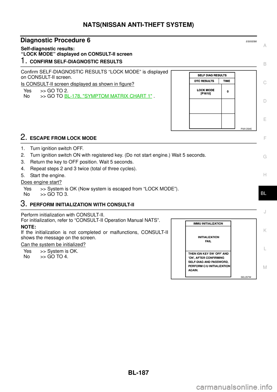
“LOCK MODE” displayed on CONSULT-II screen
1.CONFIRM SELF-DIAGNOSTIC RESULTS
Confirm SELF-DIAGNOSTIC RESULTS “LOCK MODE” is displayed
on CONSULT-II screen.
Is CONSULT-II screen displayed as shown in figure?
Ye s > > G O T O 2 .
No >> GO TOBL-178, "
SYMPTOM MATRIX CHART 1".
2.ESCAPE FROM LOCK MODE
1. Turn ignition switch OFF.
2. Turn ignition switch ON with registered key. (Do not start engine.) Wait 5 seconds.
3. Return the key to OFF position. Wait 5 seconds.
4. Repeat steps 2 and 3 twice (total of three cycles).
5. Start the engine.
Does engine start?
Yes >>SystemisOK(Nowsystemisescapedfrom“LOCKMODE”).
No >> GO TO 3.
3.PERFORM INITIALIZATION WITH CONSULT-II
Perform initialization with CONSULT-II.
For initialization, refer to “CONSULT-II Operation Manual NATS”.
NOTE:
If the initialization is not completed or malfunctions, CONSULT-II
shows the message on the screen.
Can the system be initialized?
Yes >>SystemisOK.
No >> GO TO 4.
PIIA1264E
SEL297W
Page 821 of 3171

SERVICE DATA AND SPECIFICATIONS (SDS)
BR-35
C
D
E
G
H
I
J
K
L
MA
B
BR
SERVICE DATA AND SPECIFICATIONS (SDS)PFP:00030
General SpecificationsEFS005T8
Unit: mm (in)
Brake PedalEFS005T9
Unit: mm (in)
Brake BoosterEFS005TA
Va c u u m t y p e
Unit: mm (in)
Check ValveEFS005TB
Front Disc BrakeEFS005TC
Unit: mm (in) Front brake Brake model CLZ33VB
Cylinder bore diameter 46.4 (1.83)´2
Pad length´width´thickness 140´47.8´11 ( 5 . 5 1´1.88´0.43)
Rotor outer diameter´thickness 296´28 (11.65´1.10)
Rear brake Brake model LT30
Cylinder bore diameter 38.1 (1.50)
Lining Length´width´thickness 295´55´5.5 (11.61´2.17´0.22)
Drum inner diameter 295 (11.61)
Master cylinder Cylinder bore diameter 25.4 (1.0)
Control valve Valve model Electric brake force distribution
Brake booster Booster model C215T
Diaphragm diameterPrimary 228.5 (9.0)
Secondary 203 (8.0)
Recommended brake fluid DOT 3 or DOT 4
Brake pedal height (From dash lower panel top surface)LHD modelA/T 164.1-174.1 (6.46-6.85)
M/T 171.2-181.2 (6.74-7.13)
RHD modelA/T 174.7-184.7 (6.88-7.27)
M/T 182.1-192.1 (7.17-7.56)
Brake pedal depressed height [Under a force of 490 N (50 kg, 110 lb)
with the engine running]LHD model 120 (4.72) or more
RHD model 110 (4.33) or more
Clearance between bracket and the threaded end of the stop lamp switch 0.74 - 1.96 (0.0291 - 0.0772)
Pedal play3-11(0.12-0.43)
Input rod installation standard dimension 145 - 152 (5.71 - 5.98)
Vacuum leakage
[at vacuum of –66.7 kPa (–500 mmHg, –19.69 inHg)]within 1.3 kPa (10 mmHg, 0.39 inHg) of vacuum for 15 seconds
Brake modelCLZ33VB
Brake padStandard thickness 11.0 (0.43)
Repair limit thickness 2.0 (0.08)
Disc rotorStandard thickness 28.0 (1.102)
Repair limit 26.0 (1.024)
Thickness variation (measured at 8 positions) 0.005 (0.0002)
Runout limit (with it attached to the vehicle) 0.05 (0.002)
Page 872 of 3171

CL-8
CLUTCH FLUID
CLUTCH FLUID
PFP:00017
Air Bleeding ProcedureECS00ICI
NOTE:
Do not use a vacuum assist or any other type of power bleeder on this system. Use of a vacuum assist or
power bleeder will not purge all the air from the system.
CAUTION:
lMonitor clutch fluid level in reservoir tank to make sure it
does not empty.
lKeep painted surface on the body or other parts free of
clutch fluid. If it spills, wipe up immediately and wash the
affected area with water.
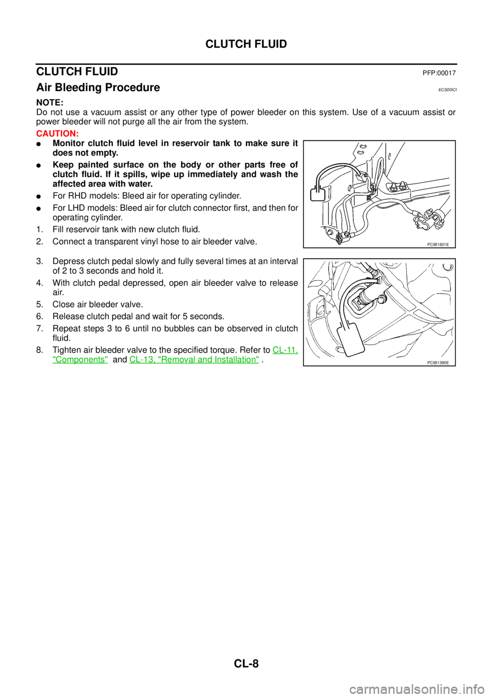
lFor RHD models: Bleed air for operating cylinder.
lFor LHD models: Bleed air for clutch connector first, and then for
operating cylinder.
1. Fill reservoir tank with new clutch fluid.
2. Connect a transparent vinyl hose to air bleeder valve.
3. Depress clutch pedal slowly and fully several times at an interval
of 2 to 3 seconds and hold it.
4. With clutch pedal depressed, open air bleeder valve to release
air.
5. Close air bleeder valve.
6. Release clutch pedal and wait for 5 seconds.
7. Repeat steps 3 to 6 until no bubbles can be observed in clutch
fluid.
8. Tighten air bleeder valve to the specified torque. Refer toCL-11,
"Components"andCL-13, "Removal and Installation".
PCIB1601E
PCIB1390E
Page 893 of 3171

ENGINE COOLANT
CO-9
C
D
E
F
G
H
I
J
K
L
MA
CO
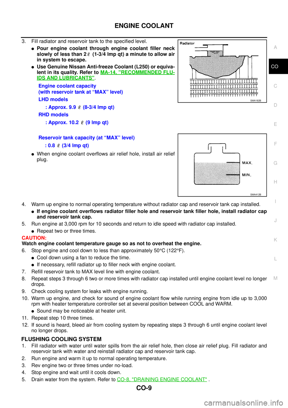
3. Fill radiator and reservoir tank to the specified level.
lPour engine coolant through engine coolant filler neck
slowly of less than 2 (1-3/4 lmp qt) a minute to allow air
in system to escape.
lUse Genuine Nissan Anti-freeze Coolant (L250) or equiva-
lent in its quality. Refer toMA-14, "
RECOMMENDED FLU-
IDS AND LUBRICANTS".
lWhen engine coolant overflows air relief hole, install air relief
plug.
4. Warm up engine to normal operating temperature without radiator cap and reservoir tank cap installed.
lIf engine coolant overflows radiator filler hole and reservoir tank filler hole, install radiator cap
and reservoir tank cap.
5. Run engine at 3,000 rpm for 10 seconds and return to idle speed with radiator cap installed.
lRepeat two or three times.
CAUTION:
Watch engine coolant temperature gauge so as not to overheat the engine.
6. Stop engine and cool down to less than approximately 50°C(122°F).
lCool down using a fan to reduce the time.
lIf necessary, refill radiator up to filler neck with engine coolant.
7. Refill reservoir tank to MAX level line with engine coolant.
8. Repeat steps 3 through 6 two or more times with radiator cap installed until engine coolant level no longer
drops.
9. Check cooling system for leaks with engine running.
10. Warm up engine, and check for sound of engine coolant flow while running engine from idle up to 3,000
rpm with heater temperature controller set at several position between COOL and WARM.
lSound may be noticeable at heater unit.
11. Repeat step 10 three times.
12. If sound is heard, bleed air from cooling system by repeating steps 3 through 6 until engine coolant level
no longer drops.
FLUSHING COOLING SYSTEM
1. Fill radiator with water until water spills from the air relief hole, then close air relief plug. Fill radiator and
reservoir tank with water and reinstall radiator cap and reservoir tank cap.
2. Run engine and warm it up to normal operating temperature.
3. Rev engine two or three times under no-load.
4. Stop engine and wait until it cools down.
5. Drain water from the system. Refer toCO-8, "
DRAINING ENGINE COOLANT". Engine coolant capacity
(with reservoir tank at “MAX” level)
LHD models
: Approx. 9.9 (8-3/4 lmp qt)
RHD models
: Approx. 10.2 (9 lmp qt)
SMA182B
Reservoir tank capacity (at “MAX” level)
: 0.8 (3/4 lmp qt)
SMA412B