2005 NISSAN NAVARA ECO mode
[x] Cancel search: ECO modePage 915 of 3171
COMBINATION METERS
DI-5
C
D
E
F
G
H
I
J
L
MA
B
DI
FUEL GAUGE
The fuel gauge indicates the approximate fuel level in the fuel tank.
Combination meter reads a resistor signal from fuel level sensor unit.
Signal is supplied
lto combination meter terminal 9
lthrough fuel level sensor unit terminal 1 and 2
lfrom combination meter terminal 4.
ODO/TRIP METER
lABS actuator and electric unit (control unit) converses a pulse signal from wheel sensor to vehicle speed
signal, and transmits vehicle speed signal to combination meter with CAN communication.
lCombination meter uses the vehicle speed signal to calculate the mileage, and it displays.
How to Change/ Reset Indication
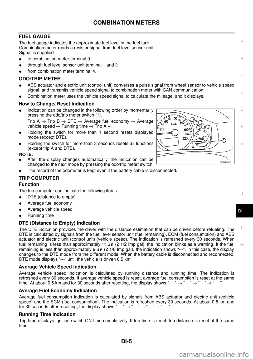
lIndication can be changed in the following order by momentarily
pressing the odo/trip meter switch (1).
–Trip A®Trip B®DTE®Average fuel economy®Average
vehicle speed®Running time®Trip A ···.
lHolding the switch for more than 1 second resets displayed
mode (except DTE).
lHolding the switch for more than 3 seconds resets all functions
(except trip A and DTE).
NOTE:
lAfter the display changes automatically, the indication can be
changed to the next mode by pressing the odo/trip meter switch.
lThe record of the odometer is kept even if the battery cable is disconnected.
TRIP COMPUTER
Function
The trip computer can indicate the following items.
lDTE (distance to empty)
lAverage fuel economy
lAverage vehicle speed
lRunning time
DTE (Distance to Empty) Indication
The DTE indication provides the driver with the distance estimation that can be driven before refueling. The
DTE is calculated by signals from the fuel level sensor unit (fuel remaining), ECM (fuel consumption) and ABS
actuator and electric unit (control unit) (vehicle speed). The indication is refreshed every 30 seconds. When
fuel remaining is less than approximately 11.6 (2 1/2 Imp gal), the indication blinks as a warning. If the fuel
remaining is less than approximately 9.6 (2 1/8 Imp gal), the indication shows “---”. In this case, the display
changes to the DTE mode from the different mode. When the battery cable is disconnected and reconnected,
DTE mode displays “---” until the vehicle is driven 0.5 km.
Average Vehicle Speed Indication
Average vehicle speed indication is calculated by running distance and running time. The indication is
refreshed every 30 seconds. If average vehicle speed is reset, average fuel consumption is reset at the same
time. At about 0.5 km and for 30 seconds after resetting, the display shows “- ”®“- ”®“-”®“ -”.
Average Fuel Economy Indication
Average fuel consumption indication is calculated by signals from ABS actuator and electric unit (vehicle
speed) and the ECM (fuel consumption). The indication is refreshed every 30 seconds. At about 0.5 km and
for 30 seconds after resetting, the display shows “- ”®“- ”®“-”®“ -”.
Running Time Indication
Trip time displays ignition switch ON time cumulatively. If trip time is reset, trip distance is reset at the same
time.
SKIB4848E
Page 916 of 3171

DI-6
COMBINATION METERS
ENGINE OIL MAINTENANCE INFORMATION
lEngine oil maintenance information displays maintenance intervals of engine oil.
lWith ignition switch ON position, engine oil maintenance information is displayed on odo/trip meter display
for 5 seconds.
NOTE:
Refer to Owner's Manual for setting.
METER ILLUMINATION CONTROL
When the lighting switch is turned ON, the odo/trip meter switch (1)
can be used to adjust the brightness of the combination meter illumi-
nation.
CLOCK
With ignition switch ON position, combination meter displays clock
on clock display. Time can be adjusted by clock switch (1). Clock can
be adjusted to 12-hour or 24-hour cycle clock.
NOTE:
If the battery cable is disconnected, the clock displays the time 12:00
in 12-hour mode.
AMBIENT AIR TEMPERATURE INDICATION
Combination meter displays ambient air temperature on clock display.
With ignition switch ON, “°C” blinks for a while. Ambient air temperature indication can be selected between
Centigrade and Fahrenheit.
Combination meter reads ambient air temperature signal from ambient sensor.
Signal is supplied
lfrom combination meter terminal 49
lthrough ambient sensor terminals 1 and 2
lto combination meter terminal 50.
When a temperature detected by sensor rises, combination meter controls increase of the indicated tempera-
ture depending on engine heat and other effective factors.
lIf the vehicle speed is more than 20 km/h, the indicated temperature rises according to the vehicle speed.
lIf the vehicle speed is less than 20 km/h, the indicated temperature is maintained.
When a temperature detected by sensor falls, the temperature is indicated immediately.
NOTE:
The range indicated on the display is between-30 and 60°C for Centigrade or between-22 and 99°Ffor
Fahrenheit.
lWhen the temperature is from-40°C(-40°F) to-30°C(-22°F), “--°C” is indicated on the display as
over range.
lWhen the temperature is under-40°C(-40°F) or over 60°C(140°F), nothing is indicated.
lWhen indicated temperature becomes less than 3°C(37°F), ambient air temperature indication blinks
warning. After blinking for 20 seconds, only “°C” blinks. At more than 4°C(39°F) the display stops blink-
ing.
SKIB4848E
PKIC1129E
Page 923 of 3171
COMBINATION METERS
DI-13
C
D
E
F
G
H
I
J
L
MA
B
DI
Self-Diagnosis Mode of Combination MeterEKS00L8K
FUNCTION
The following items can be checked during self-diagnosis mode.
lSweep of gauges pointer
lPresent gauge data values
lOdo/trip meter display and clock display segments
lCondition of warning lamps/indicator lamps controlled by unified meter control unit
lBattery voltage
lDriver's seat belt buckle switch status
lCPU of unified meter control unit status
OPERATION PROCEDURE
To initiate combination meter self-diagnosis mode, refer to the following procedure.
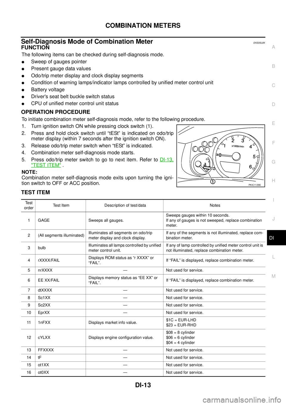
1. Turn ignition switch ON while pressing clock switch (1).
2. Press and hold clock switch until “tESt” is indicated on odo/trip
meter display (within 7 seconds after the ignition switch ON).
3. Release odo/trip meter switch when “tESt” is indicated.
4. Combination meter self-diagnosis mode starts.
5. Pressodo/tripmeterswitchtogotonextitem.RefertoDI-13,
"TEST ITEM".
NOTE:
Combination meter self-diagnosis mode exits upon turning the igni-
tion switch to OFF or ACC position.
TEST ITEM
PKIC1129E
Te s t
orderTest Item Description of test/data Notes
1 GAGE Sweeps all gauges.Sweeps gauges within 10 seconds.
If any of gauges is not sweeped, replace combination
meter.
2 (All segments illuminated)Illuminates all segments on odo/trip
meter display and clock display.If any of the segments is not illuminated, replace com-
bination meter.
3 bulbIlluminates all lamps controlled by unified
meter control unit.If any of lamp controlled by unified meter control unit is
not illuminated, replace combination meter.
4 rXXXX/FAILDisplays ROM status as “r XXXX” or
“FAIL”.If “FAIL” is displayed, replace combination meter.
5 nrXXXX — Not used for service.
6 EE XX/FAILDisplays memory status as “EE XX” or
“FAIL”.If “FAIL” is displayed, replace combination meter.
7 dtXXXX — Not used for service.
8 Sc1XX — Not used for service.
9 Sc2XX — Not used for service.
10 EprXX — Not used for service.
11 1nFXX Displays market info value.$1C = EUR-LHD
$23 = EUR-RHD
12 cYLXX Displays engine configuration value.$08 = 8 cylinder
$06 = 6 cylinder
$04 = 4 cylinder
13 FFXXXX — Not used for service.
14 tF — Not used for service.
15 ot1XX — Not used for service.
16 ot0XX — Not used for service.
Page 926 of 3171
DI-16
COMBINATION METERS
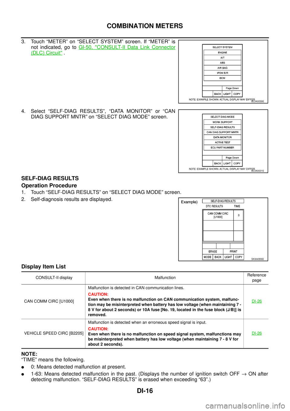
3. Touch “METER” on “SELECT SYSTEM” screen. If “METER” is
not indicated, go toGI-50, "
CONSULT-II Data Link Connector
(DLC) Circuit".
4. Select “SELF-DIAG RESULTS”, “DATA MONITOR” or “CAN
DIAG SUPPORT MNTR” on “SELECT DIAG MODE” screen.
SELF-DIAG RESULTS
Operation Procedure
1. Touch “SELF-DIAG RESULTS” on “SELECT DIAG MODE” screen.
2. Self-diagnosis results are displayed.
Display Item List
NOTE:
“TIME” means the following.
l0: Means detected malfunction at present.
l1-63: Means detected malfunction in the past. (Displays the number of ignition switch OFF®ON after
detecting malfunction. “SELF-DIAG RESULTS” is erased when exceeding “63”.)
BCIA0030E
BCIA0031E
SKIA4956E
CONSULT-II display MalfunctionReference
page
CAN COMM CIRC [U1000]Malfunction is detected in CAN communication lines.
CAUTION:
Even when there is no malfunction on CAN communication system, malfunc-
tion may be misinterpreted when battery has low voltage (when maintaining 7 -
8 V for about 2 seconds) or 10A fuse [No. 19, located in the fuse block (J/B)] is
removed.DI-26
VEHICLE SPEED CIRC [B2205]Malfunction is detected when an erroneous speed signal is input.
CAUTION:
Even when there is no malfunction on speed signal system, malfunctions may
be misinterpreted when battery has low voltage (when maintaining 7 - 8 V for
about 2 seconds).DI-26
Page 927 of 3171
COMBINATION METERS
DI-17
C
D
E
F
G
H
I
J
L
MA
B
DI
DATA MONITOR
Operation Procedure
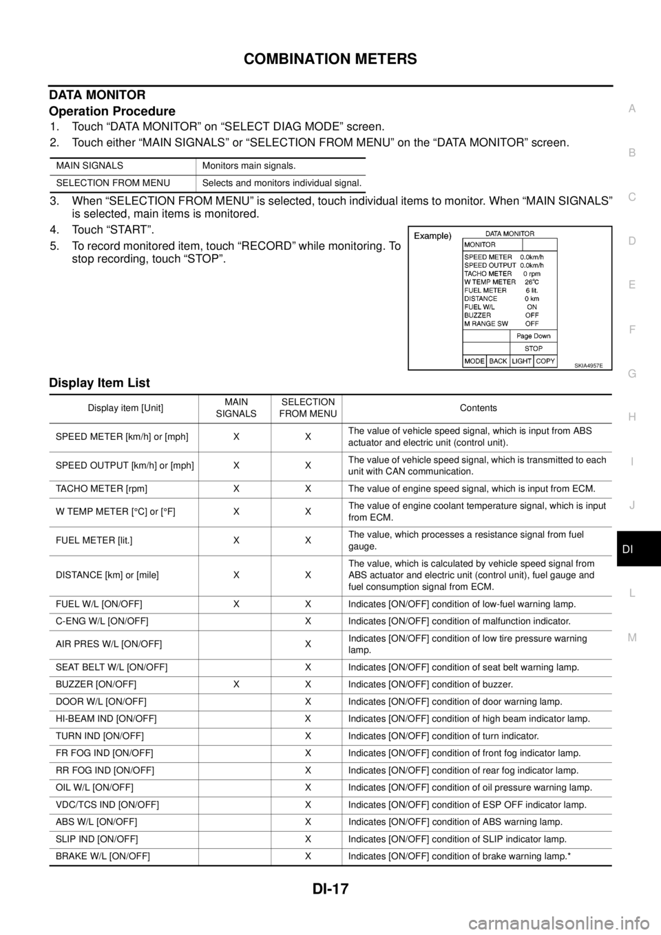
1. Touch “DATA MONITOR” on “SELECT DIAG MODE” screen.
2. Touch either “MAIN SIGNALS” or “SELECTION FROM MENU” on the “DATA MONITOR” screen.
3. When “SELECTION FROM MENU” is selected, touch individual items to monitor. When “MAIN SIGNALS”
is selected, main items is monitored.
4. Touch “START”.
5. To record monitored item, touch “RECORD” while monitoring. To
stop recording, touch “STOP”.
Display Item List
MAIN SIGNALS Monitors main signals.
SELECTION FROM MENU Selects and monitors individual signal.
SKIA4957E
Display item [Unit]MAIN
SIGNALSSELECTION
FROM MENUContents
SPEED METER [km/h] or [mph] X XThe value of vehicle speed signal, which is input from ABS
actuator and electric unit (control unit).
SPEED OUTPUT [km/h] or [mph] X XThe value of vehicle speed signal, which is transmitted to each
unit with CAN communication.
TACHO METER [rpm] X X The value of engine speed signal, which is input from ECM.
W TEMP METER [°C] or [°F] X XThe value of engine coolant temperature signal, which is input
from ECM.
FUEL METER [lit.] X XThe value, which processes a resistance signal from fuel
gauge.
DISTANCE [km] or [mile] X XThe value, which is calculated by vehicle speed signal from
ABS actuator and electric unit (control unit), fuel gauge and
fuel consumption signal from ECM.
FUEL W/L [ON/OFF] X X Indicates [ON/OFF] condition of low-fuel warning lamp.
C-ENG W/L [ON/OFF] X Indicates [ON/OFF] condition of malfunction indicator.
AIR PRES W/L [ON/OFF] XIndicates [ON/OFF] condition of low tire pressure warning
lamp.
SEAT BELT W/L [ON/OFF] X Indicates [ON/OFF] condition of seat belt warning lamp.
BUZZER [ON/OFF] X X Indicates [ON/OFF] condition of buzzer.
DOOR W/L [ON/OFF] X Indicates [ON/OFF] condition of door warning lamp.
HI-BEAM IND [ON/OFF] X Indicates [ON/OFF] condition of high beam indicator lamp.
TURN IND [ON/OFF] X Indicates [ON/OFF] condition of turn indicator.
FR FOG IND [ON/OFF] X Indicates [ON/OFF] condition of front fog indicator lamp.
RR FOG IND [ON/OFF] X Indicates [ON/OFF] condition of rear fog indicator lamp.
OIL W/L [ON/OFF] X Indicates [ON/OFF] condition of oil pressure warning lamp.
VDC/TCS IND [ON/OFF] X Indicates [ON/OFF] condition of ESP OFF indicator lamp.
ABS W/L [ON/OFF] X Indicates [ON/OFF] condition of ABS warning lamp.
SLIP IND [ON/OFF] X Indicates [ON/OFF] condition of SLIP indicator lamp.
BRAKE W/L [ON/OFF] X Indicates [ON/OFF] condition of brake warning lamp.*
Page 962 of 3171
DI-52
WARNING CHIME
SEAT BELT WARNING CHIME
Seat belt warning chime sound for approximately 90 seconds, when vehicle speed becomes more than 25 km/
h (16 MPH) with driver seat belt unfastened.
When driver seat belt is unfastened, ground is supplied as signal
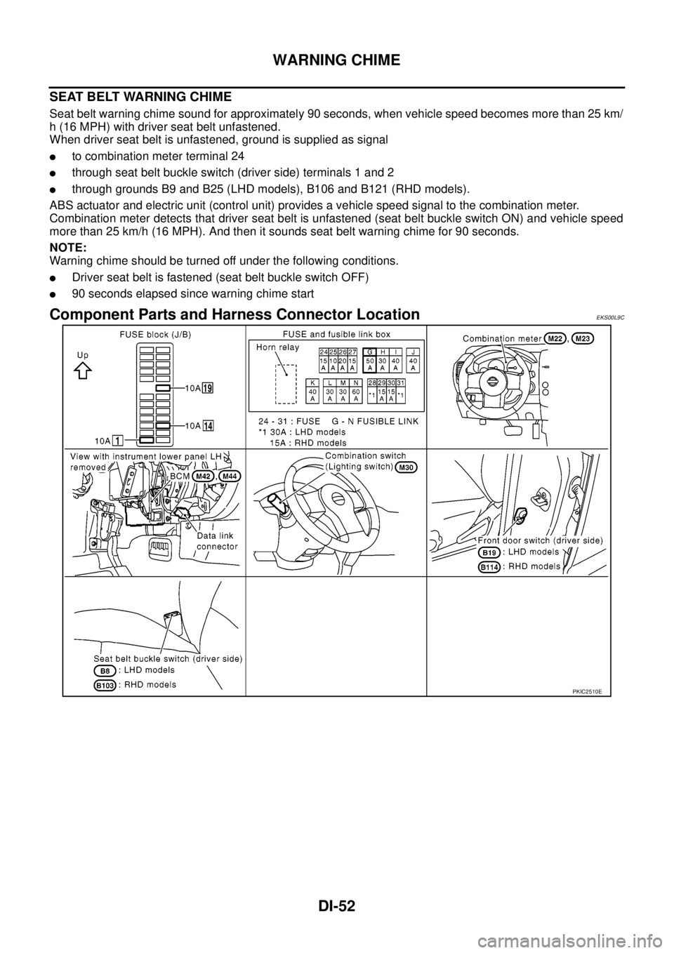
lto combination meter terminal 24
lthrough seat belt buckle switch (driver side) terminals 1 and 2
lthrough grounds B9 and B25 (LHD models), B106 and B121 (RHD models).
ABS actuator and electric unit (control unit) provides a vehicle speed signal to the combination meter.
Combination meter detects that driver seat belt is unfastened (seat belt buckle switch ON) and vehicle speed
more than 25 km/h (16 MPH). And then it sounds seat belt warning chime for 90 seconds.
NOTE:
Warning chime should be turned off under the following conditions.
lDriver seat belt is fastened (seat belt buckle switch OFF)
l90 seconds elapsed since warning chime start
Component Parts and Harness Connector LocationEKS00L9C
PKIC2510E
Page 969 of 3171
WARNING CHIME
DI-59
C
D
E
F
G
H
I
J
L
MA
B
DI
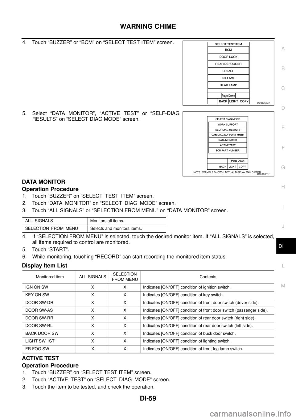
4. Touch “BUZZER” or “BCM” on “SELECT TEST ITEM” screen.
5. Select “DATA MONITOR”, “ACTIVE TEST” or “SELF-DIAG
RESULTS” on “SELECT DIAG MODE” screen.
DATA MONITOR
Operation Procedure
1. Touch “BUZZER” on “SELECT TEST ITEM” screen.
2. Touch “DATA MONITOR” on “SELECT DIAG MODE” screen.
3. Touch “ALL SIGNALS” or “SELECTION FROM MENU” on “DATA MONITOR” screen.
4. If “SELECTION FROM MENU” is selected, touch the desired monitor item. If “ALL SIGNALS” is selected,
all items required to control are monitored.
5. Touch “START”.
6. While monitoring, touching “RECORD” can start recording the monitored item status.
Display Item List
ACTIVE TEST
Operation Procedure
1. Touch “BUZZER” on “SELECT TEST ITEM” screen.
2. Touch “ACTIVE TEST” on “SELECT DIAG MODE” screen.
3. Touch the item to be tested, and check the operation.
PKIB4914E
BCIA0031E
ALL SIGNALS Monitors all items.
SELECTION FROM MENU Selects and monitors items.
Monitored item ALL SIGNALSSELECTION
FROM MENUContents
IGN ON SW X X Indicates [ON/OFF] condition of ignition switch.
KEY ON SW X X Indicates [ON/OFF] condition of key switch.
DOOR SW-DR X X Indicates [ON/OFF] condition of front door switch (driver side).
DOOR SW-AS X X Indicates [ON/OFF] condition of front door switch (passenger side).
DOOR SW-RR X X Indicates [ON/OFF] condition of rear door switch (right side).
DOOR SW-RL X X Indicates [ON/OFF] condition of rear door switch (left side).
BACK DOOR SW X X Indicates [ON/OFF] condition of buck door switch.
LIGHT SW 1ST X X Indicates [ON/OFF] condition of lighting switch.
FR FOG SW X X Indicates [ON/OFF] condition of front fog lamp switch.
Page 1004 of 3171
EC-24
BASIC SERVICE PROCEDURE
Fuel Pump Learning Value Clearing
EBS01KCL
DESCRIPTION
In order to always keep optimum fuel pressure in fuel rail, the ECM controls fuel pump in high precision with
monitoring the signal of fuel rail pressure sensor.
Accordingly, the ECM always learns characteristic value of fuel pump. Fuel Pump Learning Value Clearing is
an operation to clear the value of the fuel pump learning.
Fuel Pump Learning Value Clearing should be performed under the following conditions.
lFuel pump is changed.
lECM is replaced with used one which stores the fuel pump learning value of other fuel pump.
OPERATION PROCEDURE
NOTE:
When removing fuel pump, perform Fuel Pump Learning Value Clearing before starting engine.
With CONSULT-II
1. Turn ignition switch ON.
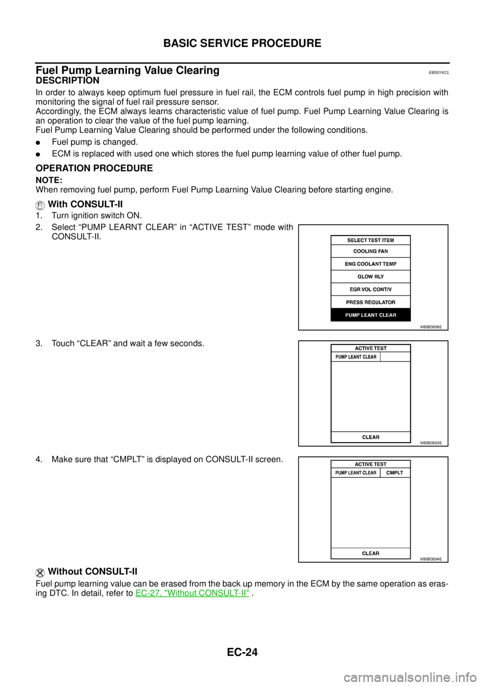
2. Select “PUMP LEARNT CLEAR” in “ACTIVE TEST” mode with
CONSULT-II.
3. Touch “CLEAR” and wait a few seconds.
4. Make sure that “CMPLT” is displayed on CONSULT-II screen.
Without CONSULT-II
Fuel pump learning value can be erased from the back up memory in the ECM by the same operation as eras-
ingDTC.Indetail,refertoEC-27, "
Without CONSULT-II".
MBIB0896E
MBIB0893E
MBIB0894E