2004 MITSUBISHI ENDEAVOR Battery terminals
[x] Cancel search: Battery terminalsPage 401 of 3870
step.
2. Erase, then retrieve DTCs. Turn ignition off. If DTC B1483 is retrieved, go to
next step. If DTC B1483 is not retrieved, an intermittent condition may exist.
3. Remove driver-side air bag module. See DRIVER
-SIDE AIR BAG
MODULE & CLOCKSPRING
under REMOVAL & INSTALLATION.
Disconnect driver-side air bag module connector C-305. See Fig. 30
. Connect
Load Resistor (MB991865) to upper clockspring connector using Load
Resistor Adapter (MB991866). Insert load resistor adapter leads into terminals
No. 3 (Yellow/Green wire) and No. 4 (Yellow/Black wire) of connector C-305.
See Fig. 31
. Connect negative battery cable. Erase, then retrieve DTCs. If
DTC B1483 is retrieved, go to next step. If DTC B1483 is not retrieved,
replace driver-side air bag module. Go to step 7 .
4. Disconnect negative battery cable. Disconnect lower clockspring connector C-
307. Connect load resistor and load resistor adapter to terminals No. 11
(Yellow/Blue wire) and No. 12 (Yellow/Violet wire) on harness-side of
connector C-307. See Fig. 32
. Reconnect negative battery cable. Erase, then
retrieve DTCs. If DTC B1483 is retrieved, replace clockspring. Go to step 7 . I
f
DTC B1483 is not retrieved, go to next step.
5. Disconnect negative battery cable. Disconnect clockspring connector C-307.
Disconnect SRS ECU connector. Release SRS ECU connector shorting bar
using a cable tie. Measure resistance between ground and SRS ECU terminal
No. 33 (Yellow/Blue wire) and No. 34 (Yellow/Violet wire). See Fig. 33
. If
resistance is not infinite at both terminals, go to next step. If resistance is
infinite at both terminals, reconnect components. Erase, then retrieve DTCs. If
DTC B1483 is retrieved, replace SRS ECU. Go to step 7 .
6. Replace wire harness between SRS ECU and clockspring. Go to next step.
7. Reconnect all SRS components. Activate air bag system. Using scan tool,
retrieve DTCs. If DTC B1483 is retrieved, go to step 1 . If DTC B1401 is not
retrieved, system is normal at this time.
DTC B1484: DRIVER-SIDE AIR BAG MODULE ACTIVATION CIRCUIT SHORT 1. Connect scan tool to Data Link Connector (DLC). See INITIAL SRS
DIAGNOSTIC PROCEDURE
under DIAGNOSTICS. If scan tool is able to
dia
gnose CAN bus lines and CAN bus lines are satis
factor
y, go to next ste
p. If
2004 Mitsubishi Endeavor Limited
2004 ACCESSORIES/SAFETY EQUIPMENT Mitsubishi - Air Bag Restraint Systems
Page 408 of 3870
Fig. 33
& Fig. 41
. If wire is okay, erase, then retrieve DTCs. If DTC B1489 is
retrieved, replace SRS ECU. Go to next step. If wire is not okay, repair as
necessary. Go to next step.
6. Reconnect all SRS components. Activate air bag system. Using scan tool,
retrieve DTCs. If DTC B1489 is retrieved, go to step 1 . If DTC B1489 is not
retrieved, system is normal at this time.
DTC B1490: PASSENGER-SIDE AIR BAG MODULE SECOND-STAGE SHORT CIRCUIT 1. Connect scan tool to Data Link Connector (DLC). See INITIAL SRS
DIAGNOSTIC PROCEDURE
under DIAGNOSTICS. If scan tool is able to
diagnose CAN bus lines and CAN bus lines are satisfactory, go to next step. If
scan tool cannot diagnose CAN bus lines, repair CAN bus lines. Go to next
step.
2. Erase, then retrieve DTCs. Turn ignition off. If DTC B1490 is retrieved, go to
next step. If DTC B1490 is not retrieved, an intermittent condition may exist.
3. Turn ignition on. If DTC B1519 is retrieved by scan tool, go to next step. If
DTC B1519 is not retrieved by scan tool, go to step 5 .
4. Inspect SRS ECU connector C-26. See SRS ELECTRONIC CONTROL
UNIT (SRS ECU)
under REMOVAL & INSTALLATION. See Fig. 30
. If
connectors are connected correctly, go to next step. If connectors are not
connected correctly, reconnect correctly. Go to step 9 .
5. Disconnect negative battery cable. Disconnect, then reconnect SRS ECU
connector C-26 and passenger-side air bag module C-09. Connect negative
battery cable. Using scan tool, erase, then retrieve DTCs. If DTC B1490 is
retrieved, go to next step. If DTC B1490 is not retrieved, intermittent condition
may have existed.
6. Disconnect negative battery cable. Disconnect passenger-side air bag module
connector C-09. See PASSENGER
-SIDE AIR BAG MODULE
under
REMOVAL & INSTALLATION. Connect Load Resistor (MB991865) to
Load Resistor Adapter (MB991866). Insert load resistor adapter leads into
harness-side terminals No. 3 (Yellow/Pink wire) and No. 4 (Yellow/Gray wire)
of connector C-09. See Fig. 35
. Connect negative battery cable. Erase, then
retrieve DTCs. If DTC B1490 is retrieved, go to next step. If DTC B1490 is
not retrieved, re
place
passen
ger-side air ba
g module.
2004 Mitsubishi Endeavor Limited
2004 ACCESSORIES/SAFETY EQUIPMENT Mitsubishi - Air Bag Restraint Systems
Page 409 of 3870
7. Disconnect negative battery cable. Remove load resistor and load resistor
adapter from passenger-side air bag module connector C-09. Disconnect SRS
ECU connector. Release SRS ECU connector shorting bar using a cable tie.
Measure resistance between SRS ECU connector terminals No. 31
(Yellow/Pink wire) and No. 30 (Yellow/Gray wire). If continuity exits, go to
next step. If continuity does not exist, reconnect SRS components. Erase, then
retrieve DTCs. If DTC B1490 is retrieved, replace SRS ECU. Go to step 9 .
8. Replace wire harness between SRS ECU and passenger-side air bag module.
Go to next step.
9. Reconnect all SRS components. Activate air bag system. Using scan tool,
retrieve DTCs. If DTC B1490 is retrieved, go to step 1 . If DTC B1490 is not
retrieved, system is normal at this time. DTC B1491: PASSENGER-SIDE AIR BAG MODULE SECOND-STAGE OPEN CIRCUIT 1. Connect scan tool to Data Link Connector (DLC). See INITIAL SRS
DIAGNOSTIC PROCEDURE
under DIAGNOSTICS. If scan tool is able to
diagnose CAN bus lines and CAN bus lines are satisfactory, go to next step. If
scan tool cannot diagnose CAN bus lines, repair CAN bus lines. Go to next
step.
2. Erase, then retrieve DTCs. Turn ignition off. If DTC B1491 is retrieved, go to
next step. If DTC B1491 is not retrieved, an intermittent condition may exist.
3. Disconnect negative battery cable. Disconnect passenger-side air bag module
connector C-09. See PASSENGER
-SIDE AIR BAG MODULE
under
REMOVAL & INSTALLATION. See Fig. 30
. Connect Load Resistor
(MB991865) to Load Resistor Adapter (MB991866). Insert load resistor
adapter leads into harness-side terminals No. 3 (Yellow/Pink wire) and No. 4
(Yellow/GRay wire) of connector C-09. See Fig. 35
. Connect negative battery
cable. Erase, then retrieve DTCs. If DTC B1491 is retrieved, go to next step. If
DTC B1491 is not retrieved, replace passenger-side air bag module. Go to step
5 .
4. Disconnect negative battery cable. Remove load resistor and load resistor
adapter from connector C-09. Disconnect SRS ECU connector. See SRS
ELECTRONIC CONTROL UNIT (SRS ECU)
under REMOVAL &
INSTALLATION. Release SRS ECU connector shortin
g bar usin
g a cable tie.
2004 Mitsubishi Endeavor Limited
2004 ACCESSORIES/SAFETY EQUIPMENT Mitsubishi - Air Bag Restraint Systems
Page 410 of 3870
Measure resistance of Yellow/Pink wire between SRS ECU connector terminal
No. 31 and passenger-side air bag module connector C-09, terminal No. 3. See
Fig. 33
& Fig. 35
. Measure resistance of Yellow/Gray wire between SRS
ECU connector terminal No. 30 and passenger-side air bag module connector
C-09, terminal No. 4. If resistance is more than 2 ohms in either wire, replace
wire harness between SRS ECU and passenger-side air bag module. Go to next
step. If resistance is less than 2 ohms in both wires, reconnect SRS
components. Erase, then retrieve DTCs. If DTC B1491 is retrieved, replace
SRS ECU. Go to next step
5. Reconnect all SRS components. Activate air bag system. Using scan tool,
retrieve DTCs. If DTC B1491 is retrieved, go to step 1 . If DTC B1491 is not
retrieved, system is normal at this time.
DTC B1492: PASSENGER-SIDE AIR BAG MODULE SECOND-STAGE CIRCUIT SHORT TO
VOLTAGE 1. Connect scan tool to Data Link Connector (DLC). See INITIAL SRS
DIAGNOSTIC PROCEDURE
under DIAGNOSTICS. If scan tool is able to
diagnose CAN bus lines and CAN bus lines are satisfactory, go to next step. If
scan tool cannot diagnose CAN bus lines, repair CAN bus lines. Go to next
step.
2. Erase, then retrieve DTCs. Turn ignition off. If DTC B1492 is retrieved, go to
next step. If DTC B1492 is not retrieved, an intermittent condition may exist.
3. Disconnect negative battery cable. Disconnect passenger-side air bag module
connector C-09. See PASSENGER
-SIDE AIR BAG MODULE
under
REMOVAL & INSTALLATION. See Fig. 30
. Connect Load Resistor
(MB991865) to Load Resistor Adapter (MB991866). Insert load resistor
adapter leads into harness-side terminals No. 3 (Yellow/Pink wire) and No. 4
(Yellow/Gray wire) of connector C-09. See Fig. 35
. Connect negative battery
cable. Erase, then retrieve DTCs. If DTC B1492 is retrieved, go to next step. If
DTC B1492 is not retrieved, replace passenger-side air bag module. Go to step
5 .
4. Disconnect negative battery cable. Remove load resistor and load resistor
adapter from passenger-side air bag module connector C-09. Disconnect SRS
ECU connector C-26. See SRS ELECTRONIC CONTROL UNIT (SRS
ECU
) under REMOVAL & INSTALLATION. Release SRS ECU connecto
r
2004 Mitsubishi Endeavor Limited
2004 ACCESSORIES/SAFETY EQUIPMENT Mitsubishi - Air Bag Restraint Systems
Page 411 of 3870
shorting bar using a cable tie. Measure voltage between ground and SRS ECU
connector terminals No. 31 (Yellow/Pink wire) and No. 30 (Yellow/Gray
wire). See Fig. 33
. If voltage is measured at either terminal, go to next step. If
voltage is not measured at either terminal, reconnect SRS components. Erase,
then retrieve DTCs. If DTC B1492 is retrieved, replace SRS ECU. Go to step
6 .
5. Replace wire harness between SRS ECU and passenger-side air bag module.
Go to next step.
6. Reconnect all SRS components. Activate air bag system. Using scan tool,
retrieve DTCs. If DTC B1492 is retrieved, go to step 1 . If DTC B1492 is not
retrieved, system is normal at this time.
DTC B1493: PASSENGER-SIDE AIR BAG MODULE SECOND-STAGE SHORT TO GROUND 1. Connect scan tool to Data Link Connector (DLC). See INITIAL SRS
DIAGNOSTIC PROCEDURE
under DIAGNOSTICS. If scan tool is able to
diagnose CAN bus lines and CAN bus lines are satisfactory, go to next step. If
scan tool cannot diagnose CAN bus lines, repair CAN bus lines. Go to next
step.
2. Erase, then retrieve DTCs. Turn ignition off. If DTC B1493 is retrieved, go to
next step. If DTC B1493 is not retrieved, an intermittent condition may exist.
3. Disconnect negative battery cable. Disconnect passenger-side air bag module
connector C-09. See PASSENGER
-SIDE AIR BAG MODULE
under
REMOVAL & INSTALLATION. See Fig. 30
. Connect Load Resistor
(MB991865) to Load Resistor Adapter (MB991866). Insert load resistor
adapter leads into harness-side terminals No. 3 (Yellow/Pink wire) and No. 4
(Yellow/Gray wire) of connector C-09. See Fig. 35
. Connect negative battery
cable. Erase, then retrieve DTCs. If DTC B1493 is retrieved, go to next step. If
DTC B1493 is not retrieved, replace passenger-side air bag module. Go to step
6 .
4. Disconnect negative battery cable. Remove load resistor and load resistor
adapter from passenger-side air bag module connector C-09. Disconnect SRS
ECU connector C-26. See SRS ELECTRONIC CONTROL UNIT (SRS
ECU)
under REMOVAL & INSTALLATION. Release SRS ECU connector
shorting bar usin
g a cable tie. Measure resistance
between
ground and SRS
2004 Mitsubishi Endeavor Limited
2004 ACCESSORIES/SAFETY EQUIPMENT Mitsubishi - Air Bag Restraint Systems
Page 414 of 3870
DIAGNOSTIC PROCEDURE
under DIAGNOSTICS. If scan tool is able to
diagnose CAN bus lines and CAN bus lines are satisfactory, go to next step. If
scan tool cannot diagnose CAN bus lines, repair CAN bus lines. Go to next
step.
2. Erase, then retrieve DTCs. If DTC B1498 is retrieved, replace SRS ECU. See
SRS ELECTRONIC CONTROL UNIT (SRS ECU)
under REMOVAL &
INSTALLATION. If DTC B1499 is not retrieved, an intermittent condition
may exist.
DTC B1506: SEAT SLIDE SENSOR OPEN 1. Connect scan tool to Data Link Connector (DLC). See INITIAL SRS
DIAGNOSTIC PROCEDURE
under DIAGNOSTICS. If scan tool is able to
diagnose CAN bus lines and CAN bus lines are satisfactory, go to next step. If
scan tool cannot diagnose CAN bus lines, repair CAN bus lines. Go to next
step.
2. Erase, then retrieve DTCs. Turn ignition off. If DTC B1506 is retrieved, go to
next step. If DTC B1506 is not retrieved, an intermittent condition may exist.
3. Disconnect negative battery cable. Disconnect seat slide sensor connector D-
37, located under passenger-side front seat. See SEAT SLIDE SENSOR
under REMOVAL & INSTALLATION. Connect Load Resistor (MB991865)
to Load Resistor Adapter (MB991866). Insert load resistor adapter leads into
harness-side terminals No. 1 (Brown wire) and No. 2 (Brown/White wire) of
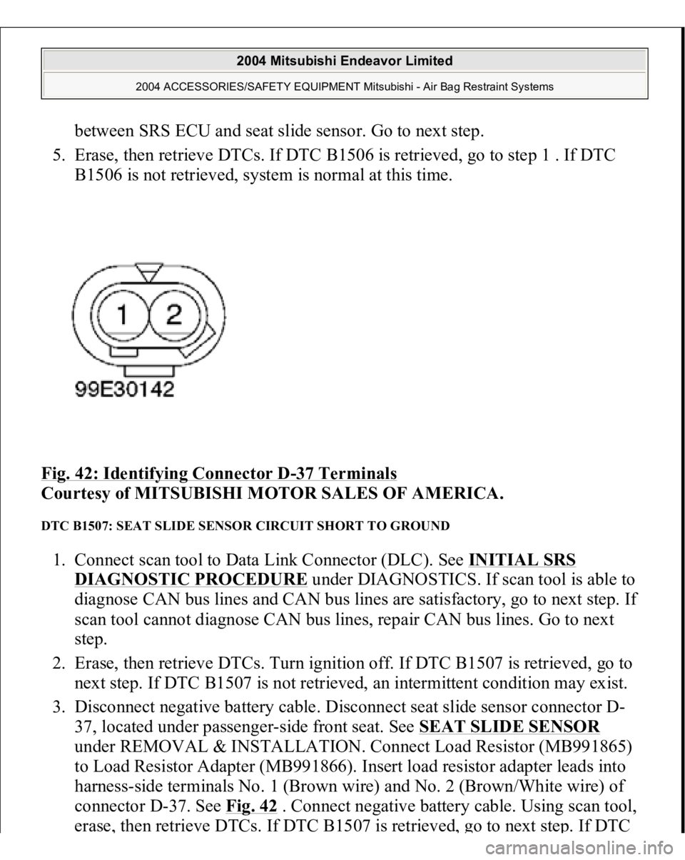
connector D-37. See Fig. 42
. Connect negative battery cable. Using scan tool,
erase, then retrieve DTCs. If DTC B1506 is retrieved, go to next step. If DTC
B1506 is not retrieved, replace seat slide sensor. Go to step 5 .
4. Disconnect SRS ECU connector C-40. See SRS ELECTRONIC CONTROL
UNIT (SRS ECU)
under REMOVAL & INSTALLATION. See Fig. 30
.
Remove load resistor and load resistor adapter from connector D-37. Check
continuity in Brown wire between SRS ECU connector C-40, terminal No. 2
and connector D-37, terminal No. 1. See Fig. 33
. Check continuity in
Brown/White wire between SRS ECU connector C-40, terminal No. 1 and
connector D-37, terminal No. 2. If continuity exists in both wires, reconnect
SRS components. Erase, then retrieve DTCs. If DTC B1506 is retrieved,
replace SRS ECU. If continuity does not exist either wire, replace wire harness
2004 Mitsubishi Endeavor Limited
2004 ACCESSORIES/SAFETY EQUIPMENT Mitsubishi - Air Bag Restraint Systems
Page 415 of 3870
between SRS ECU and seat slide sensor. Go to next step.
5. Erase, then retrieve DTCs. If DTC B1506 is retrieved, go to step 1 . If DTC
B1506 is not retrieved, system is normal at this time.
Fig. 42: Identifying Connector D
-37 Terminals
Courtesy of MITSUBISHI MOTOR SALES OF AMERICA.
DTC B1507: SEAT SLIDE SENSOR CIRCUIT SHORT TO GROUND 1. Connect scan tool to Data Link Connector (DLC). See INITIAL SRS
DIAGNOSTIC PROCEDURE
under DIAGNOSTICS. If scan tool is able to
diagnose CAN bus lines and CAN bus lines are satisfactory, go to next step. If
scan tool cannot diagnose CAN bus lines, repair CAN bus lines. Go to next
step.
2. Erase, then retrieve DTCs. Turn ignition off. If DTC B1507 is retrieved, go to
next step. If DTC B1507 is not retrieved, an intermittent condition may exist.
3. Disconnect negative battery cable. Disconnect seat slide sensor connector D-
37, located under passenger-side front seat. See SEAT SLIDE SENSOR
under REMOVAL & INSTALLATION. Connect Load Resistor (MB991865)
to Load Resistor Adapter (MB991866). Insert load resistor adapter leads into
harness-side terminals No. 1 (Brown wire) and No. 2 (Brown/White wire) of
connector D-37. See Fig. 42
. Connect negative battery cable. Using scan tool,
erase
, then retrieve DTCs. If DTC B1507 is retrieved
, go to next ste
p. If DTC
2004 Mitsubishi Endeavor Limited
2004 ACCESSORIES/SAFETY EQUIPMENT Mitsubishi - Air Bag Restraint Systems
Page 416 of 3870
B1507 is not retrieved, replace seat slide sensor. Go to step 5 .
4. Disconnect SRS ECU connector C-40. See SRS ELECTRONIC CONTROL UNIT (SRS ECU)
under REMOVAL & INSTALLATION. See Fig. 30
.
Remove load resistor and load resistor adapter from connector D-37. Measure
resistance between ground and SRS ECU connector C-40, terminal No. 2
(Brown wire). See Fig. 33
. Measure resistance between ground and SRS ECU
connector C-40, terminal No. 1 (Brown/White wire). If resistance is infinite at
both terminals, reconnect SRS components. Erase, then retrieve DTCs. If DTC
B1507 is retrieved, replace SRS ECU. If resistance is not infinite at both
terminals, replace wire harness between SRS ECU and seat slide sensor. Go to
next step.
5. Erase, then retrieve DTCs. If DTC B1507 is retrieved, go to step 1 . If DTC
B1507 is not retrieved, system is normal at this time.
DTC B1508: SEAT SLIDE SENSOR CIRCUIT SHORT TO VOLTAGE 1. Connect scan tool to Data Link Connector (DLC). See INITIAL SRS
DIAGNOSTIC PROCEDURE
under DIAGNOSTICS. If scan tool is able to
diagnose CAN bus lines and CAN bus lines are satisfactory, go to next step. If
scan tool cannot diagnose CAN bus lines, repair CAN bus lines. Go to next
step.
2. Erase, then retrieve DTCs. Turn ignition off. If DTC B1508 is retrieved, go to
next step. If DTC B1508 is not retrieved, an intermittent condition may exist.
3. Disconnect negative battery cable. Disconnect seat slide sensor connector D-
37, located under passenger-side front seat. See SEAT SLIDE SENSOR
under REMOVAL & INSTALLATION. Connect Load Resistor (MB991865)
to Load Resistor Adapter (MB991866). Insert load resistor adapter leads into
harness-side terminals No. 1 (Brown wire) and No. 2 (Brown/White wire) of
connector D-37. See Fig. 42
. Connect negative battery cable. Using scan tool,
erase, then retrieve DTCs. If DTC B1508 is retrieved, go to next step. If DTC
B1508 is not retrieved, replace seat slide sensor. Go to step 5 .
4. Disconnect SRS ECU connector C-40. See SRS ELECTRONIC CONTROL
UNIT (SRS ECU)
under REMOVAL & INSTALLATION. See Fig. 30
.
Remove load resistor and load resistor adapter from connector D-37. Measure
volta
ge between
ground and SRS ECU connector
C-40, terminal No. 2
(Brown
2004 Mitsubishi Endeavor Limited
2004 ACCESSORIES/SAFETY EQUIPMENT Mitsubishi - Air Bag Restraint Systems