Page 792 of 3870
2004 ENGINE COOLING
Electric Cooling Fans - Endeavor
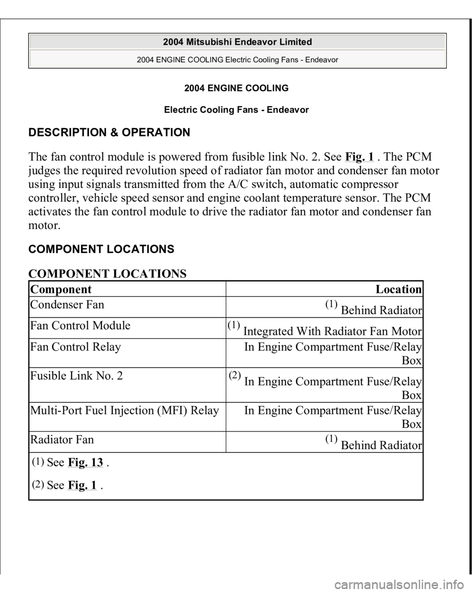
DESCRIPTION & OPERATION The fan control module is powered from fusible link No. 2. See Fig. 1
. The PCM
judges the required revolution speed of radiator fan motor and condenser fan motor
using input signals transmitted from the A/C switch, automatic compressor
controller, vehicle speed sensor and engine coolant temperature sensor. The PCM
activates the fan control module to drive the radiator fan motor and condenser fan
motor. COMPONENT LOCATIONS COMPONENT LOCATIONS Component
Location
Condenser Fan
(1) Behind Radiator
Fan Control Module
(1) Integrated With Radiator Fan Motor
Fan Control Relay
In Engine Compartment Fuse/Relay
Box
Fusible Link No. 2
(2) In Engine Compartment Fuse/Relay
Box
Multi-Port Fuel Injection (MFI) Relay
In Engine Compartment Fuse/Relay
Box
Radiator Fan
(1) Behind Radiator
(1)
See Fig. 13
.
(2)
See Fig. 1
.
2004 Mitsubishi Endeavor Limited
2004 ENGINE COOLING Electric Cooling Fans - Endeavor
2004 Mitsubishi Endeavor Limited
2004 ENGINE COOLING Electric Cooling Fans - Endeavor
Page 807 of 3870
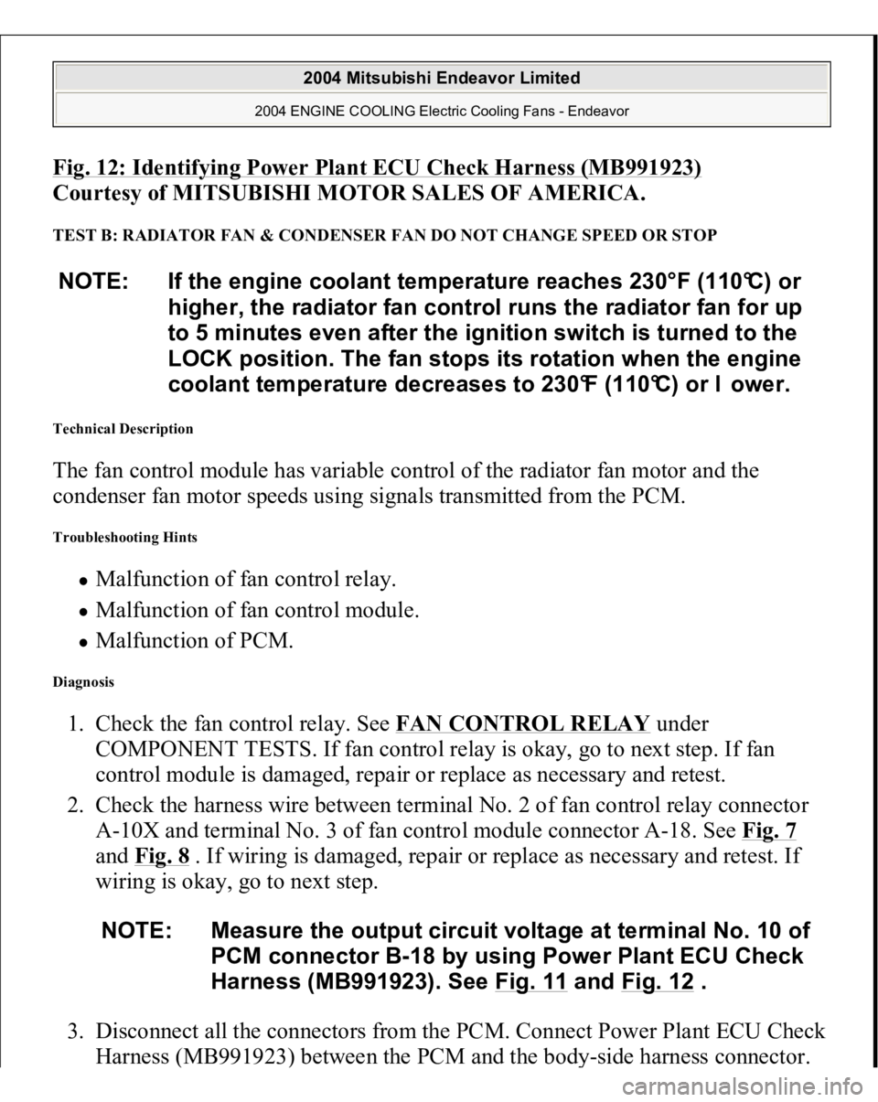
Fig. 12: Identifying Power Plant ECU Check Harness (MB991923)
Courtesy of MITSUBISHI MOTOR SALES OF AMERICA.
TEST B: RADIATOR FAN & CONDENSER FAN DO NOT CHANGE SPEED OR STOP Technical Description The fan control module has variable control of the radiator fan motor and the
condenser fan motor speeds using signals transmitted from the PCM. Troubleshooting Hints
Malfunction of fan control relay. Malfunction of fan control module. Malfunction of PCM.
Diagnosis 1. Check the fan control relay. See FAN CONTROL RELAY
under
COMPONENT TESTS. If fan control relay is okay, go to next step. If fan
control module is damaged, repair or replace as necessary and retest.
2. Check the harness wire between terminal No. 2 of fan control relay connector
A-10X and terminal No. 3 of fan control module connector A-18. See Fig. 7
and Fig. 8
. If wiring is damaged, repair or replace as necessary and retest. If
wiring is okay, go to next step.
3. Disconnect all the connectors from the PCM. Connect Power Plant ECU Check
Harness (MB991923
) between the PCM and the bod
y-side harness connector.
NOTE: If the engine coolant temperature reaches 230°F (110°C) or
higher, the radiator fan control runs the radiator fan for up
to 5 minutes even after the ignition switch is turned to the
LOCK position. The fan stops its rotation when the engine
coolant temperature decreases to 230°F (110°C) or l ower.
NOTE: Measure the output circuit voltage at terminal No. 10 of
PCM connector B-18 by using Power Plant ECU Check
Harness (MB991923). See Fig. 11
and Fig. 12
.
2004 Mitsubishi Endeavor Limited
2004 ENGINE COOLING Electric Cooling Fans - Endeavor
Page 1096 of 3870
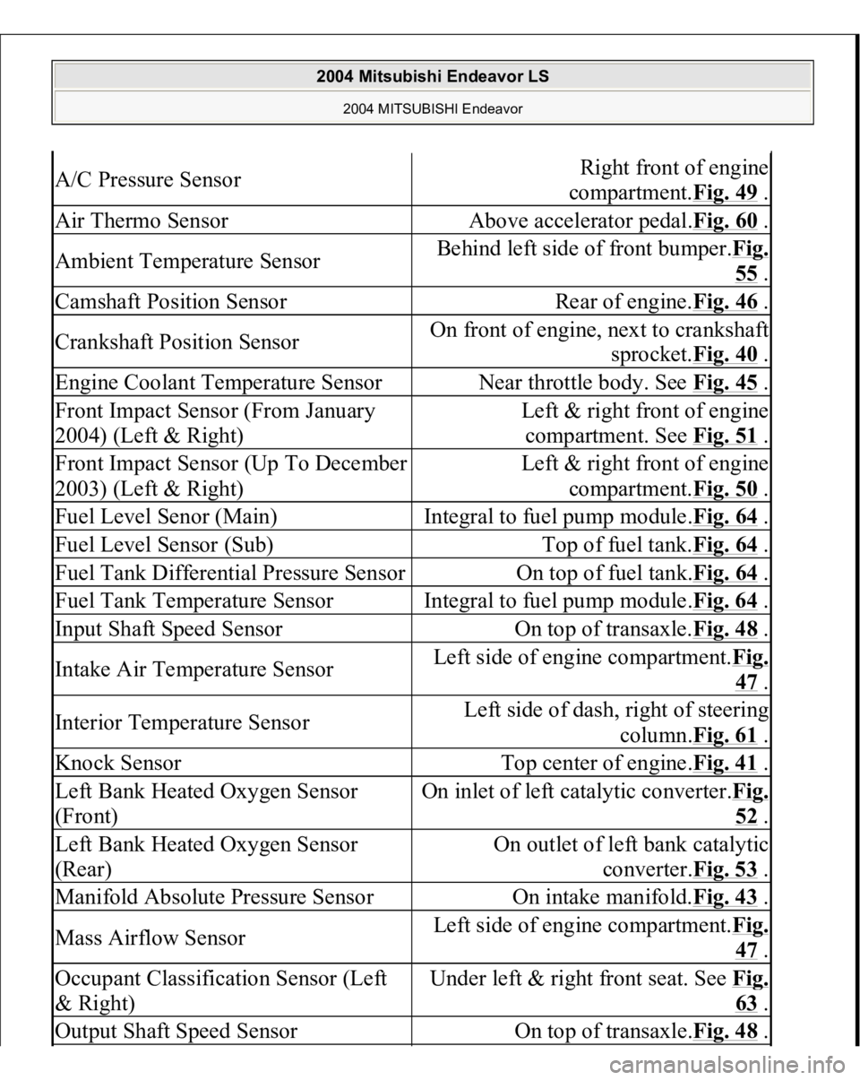
A/C Pressure Sensor
Right front of engine
compartment.Fig. 49
.
Air Thermo Sensor
Above accelerator pedal.Fig. 60
.
Ambient Temperature Sensor
Behind left side of front bumper.Fig.
55 .
Camshaft Position Sensor
Rear of engine.Fig. 46
.
Crankshaft Position Sensor
On front of engine, next to crankshaft
sprocket.Fig. 40
.
Engine Coolant Temperature Sensor
Near throttle body. See Fig. 45
.
Front Impact Sensor (From January
2004) (Left & Right)
Left & right front of engine
compartment. See Fig. 51
.
Front Impact Sensor (Up To December
2003) (Left & Right)
Left & right front of engine
compartment.Fig. 50
.
Fuel Level Senor (Main)
Integral to fuel pump module.Fig. 64
.
Fuel Level Sensor (Sub)
Top of fuel tank.Fig. 64
.
Fuel Tank Differential Pressure Sensor
On top of fuel tank.Fig. 64
.
Fuel Tank Temperature Sensor
Integral to fuel pump module.Fig. 64
.
Input Shaft Speed Sensor
On top of transaxle.Fig. 48
.
Intake Air Temperature Sensor
Left side of engine compartment.Fi
g.
47 .
Interior Temperature Sensor
Left side of dash, right of steering
column.Fig. 61
.
Knock Sensor
Top center of engine.Fig. 41
.
Left Bank Heated Oxygen Sensor
(Front)
On inlet of left catalytic converter.Fi
g.
52 .
Left Bank Heated Oxygen Sensor
(Rear)
On outlet of left bank catalytic
converter.Fig. 53
.
Manifold Absolute Pressure Sensor
On intake manifold.Fig. 43
.
Mass Airflow Sensor
Left side of engine compartment.Fi
g.
47 .
Occupant Classification Sensor (Left
& Right)
Under left & right front seat. See Fi
g.
63 .
Output Shaft Speed Sensor
On top of transaxle.Fig. 48
.
2004 Mitsubishi Endeavor LS
2004 MITSUBISHI Endeavor
Page 1188 of 3870
2004 ENGINE
Engine Cooling - Endeavor
GENERAL DESCRIPTION The cooling system is designed to keep every part of the engine at appropriate
temperature in whatever condition the engine may be operated. The cooling method
is of the water-cooled, pressure forced circulation type in which the water pump
pressurizes coolant and circulates it throughout the engine. If the coolant
temperature exceeds the prescribed temperature, the thermostat opens to circulate
the coolant through the radiator as well so that the heat absorbed by the coolant may
be radiated into the air. The water pump is of the centrifugal type and is driven by
the drive belt from the crankshaft. The radiator is the corrugated fin, down flow
type. CONSTRUCTION DIAGRAM Fig. 1: Identifying Engine Cooling Construction Diagram
2004 Mitsubishi Endeavor Limited 2004 ENGINE Engine Cooling - Endeavor
2004 Mitsubishi Endeavor Limited 2004 ENGINE Engine Cooling - Endeavor
Page 1189 of 3870
Courtesy of MITSUBISHI MOTOR SALES OF AMERICA
.
SPECIAL TOOLS Fig. 2: Identifying Engine Cooling Special Tools
Courtesy of MITSUBISHI MOTOR SALES OF AMERICA.
ENGINE COOLING DIAGNOSIS INTRODUCTION The system cools the engine so that it does not over-heat and maintains the engine
at an optimum temperature. The system components are the radiator, water pump,
thermostat, condenser fan assembly. Possible faults include low coolant,
contamination, belt loosening and component damage. TROUBLESHOOTING STRATEG
Y
2004 Mitsubishi Endeavor Limited 2004 ENGINE Engine Cooling - Endeavor
Page 1195 of 3870
Refer to 7. DRIVE BELTS (FOR GENERATOR, POWER STEERIN
G .
Q: Is the drive belt loose or damaged?
YES: Adjust or replace the drive belt, then go to Step 5.
NO: There is no action to be taken.
STEP 5. Retest the system.
Check the engine coolant temperature.
Q: Is the engine coolant temperature abnormally high?
YES: Return to Step 2 .
NO: The procedure is complete.
INSPECTION PROCEDURE 3: Radiator Fan and Condenser Fan do not Operate
2004 Mitsubishi Endeavor Limited 2004 ENGINE Engine Cooling - Endeavor
Page 1199 of 3870
Courtesy of MITSUBISHI MOTOR SALES OF AMERICA
.
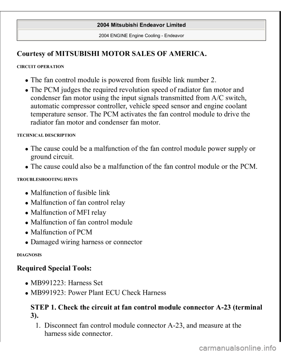
CIRCUIT OPERATION
The fan control module is powered from fusible link number 2. The PCM judges the required revolution speed of radiator fan motor and
condenser fan motor using the input signals transmitted from A/C switch,
automatic compressor controller, vehicle speed sensor and engine coolant
temperature sensor. The PCM activates the fan control module to drive the
radiator fan motor and condenser fan motor.
TECHNICAL DESCRIPTION
The cause could be a malfunction of the fan control module power supply or
ground circuit. The cause could also be a malfunction of the fan control module or the PCM.
TROUBLESHOOTING HINTS
Malfunction of fusible link Malfunction of fan control relay Malfunction of MFI relay Malfunction of fan control module Malfunction of PCM Damaged wiring harness or connector
DIAGNOSIS Required Special Tools:
MB991223: Harness Set MB991923: Power Plant ECU Check Harness
STEP 1. Check the circuit at fan control module connector A-23 (terminal
3).
1. Disconnect fan control module connector A-23, and measure at the
harness side connector.
2004 Mitsubishi Endeavor Limited 2004 ENGINE Engine Cooling - Endeavor
Page 1220 of 3870
Courtesy of MITSUBISHI MOTOR SALES OF AMERICA
.
STEP 14. Check the symptoms.
Q: Do the radiator fan and condenser fan operate correctly?
YES: The procedure is complete.
NO: Return to Step 1 .
INSPECTION PROCEDURE 4: Radiator Fan and Condenser Fan do not Change Speed or Stop Radiator Fan and Condenser Fan Drive Circuit Refer to INSPECTION PROCEDURE 3: RADIATOR FAN AND CONDENSER FAN DO NOT OPERATE
.
CIRCUIT OPERATION
The fan control module is powered from fusible link number 2. The PCM judges the required revolution speed of radiator fan motor and
condenser fan motor using the input signals transmitted from A/C switch,
automatic compressor controller, vehicle speed sensor and engine coolant
temperature sensor. The PCM activates the fan control module to drive the
radiator fan motor and condenser fan motor.
TECHNICAL DESCRIPTION The fan controller has variable control of the radiator fan motor and the condenser
fan motor speeds using signals transmitted from the PCM. TROUBLESHOOTING HINTS NOTE: If the engine coolant temperature reaches 110°C (230°F) or
higher, the radiator fan control runs the radiator fan for up
to 5 minutes even after the ignition switch is turned to the
"LOCK" (OFF) position [the fan stops its rotation when the
engine coolant temperature decreases to 110°C (230° F) or
lower.]
2004 Mitsubishi Endeavor Limited 2004 ENGINE Engine Cooling - Endeavor