Page 186 of 3870
Fig. 107: ABS
-ECU Power Supply And Ground Circuit Diagram & Connector
Identification
Courtesy of MITSUBISHI MOTOR SALES OF AMERICA.
Fig. 108: Identifying Connectors: C
-214, C
-215
Courtesy of MITSUBISHI MOTOR SALES OF AMERICA.
CIRCUIT OPERATION The ABS-ECU is energized by the ignition switch (IG2) through multi-purpose fuse
13 and the ABS-ECU terminal 20. ABS DTC SET CONDITIONS C1860 will be set when the
power su
pply volta
ge to the AB
S-ECU has decreased to
CAUTION: If there is any problem in the CAN bus lines, an
incorrect diagnostic trouble code may be set. Prior to
this diagnosis, diagnose the CAN bus lines.
2004 Mitsubishi Endeavor LS
2004 BRAKES Anti-Lock Braking System (ABS) - Endeavor
Page 327 of 3870

with fuse No. 23. See WIRING DIAGRAMS
. If continuity does not exist, go
to next step.
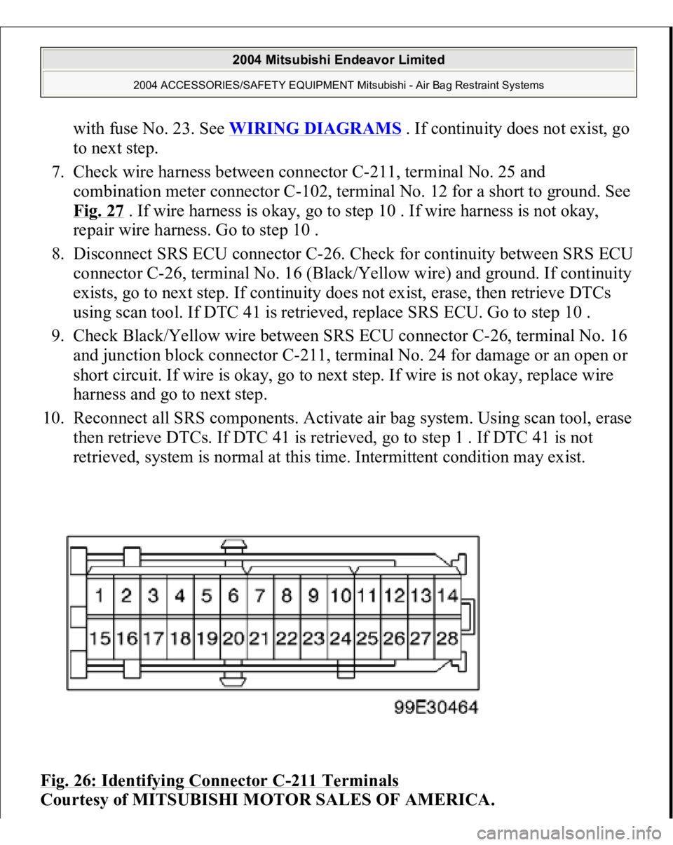
7. Check wire harness between connector C-211, terminal No. 25 and
combination meter connector C-102, terminal No. 12 for a short to ground. See
Fig. 27
. If wire harness is okay, go to step 10 . If wire harness is not okay,
repair wire harness. Go to step 10 .
8. Disconnect SRS ECU connector C-26. Check for continuity between SRS ECU
connector C-26, terminal No. 16 (Black/Yellow wire) and ground. If continuity
exists, go to next step. If continuity does not exist, erase, then retrieve DTCs
using scan tool. If DTC 41 is retrieved, replace SRS ECU. Go to step 10 .
9. Check Black/Yellow wire between SRS ECU connector C-26, terminal No. 16
and junction block connector C-211, terminal No. 24 for damage or an open or
short circuit. If wire is okay, go to next step. If wire is not okay, replace wire
harness and go to next step.
10. Reconnect all SRS components. Activate air bag system. Using scan tool, erase
then retrieve DTCs. If DTC 41 is retrieved, go to step 1 . If DTC 41 is not
retrieved, system is normal at this time. Intermittent condition may exist.
Fig. 26: Identifying Connector C
-211 Terminals
Courtesy of MITSUBISHI MOTOR SALES OF AMERICA.
2004 Mitsubishi Endeavor Limited
2004 ACCESSORIES/SAFETY EQUIPMENT Mitsubishi - Air Bag Restraint Systems
Page 396 of 3870

next step. If DTC B1477 is not retrieved, an intermittent condition may exist.
3. Remove fuse No. 23 from instrument panel junction block. See Fig. 39
. If fuse
is blown, go to step 6 . If fuse is not blown, go to next step.
4. Disconnect negative battery cable. Disconnect SRS ECU connector C-26. See
SRS ELECTRONIC CONTROL UNIT (SRS ECU)
under REMOVAL &
INSTALLATION. See Fig. 30
. Connect negative battery cable. Turn ignition
on. Measure voltage between ground and SRS ECU connector C-26, terminal
No. 24 (Black/Yellow wire). If voltage is 9 volts or more, reconnect SRS
components. Erase, then retrieve DTCs. If DTC B1477 is retrieved, replace
SRS ECU. Go to step 8 . If DTC B1477 is not retrieved, go to next step.
5. Inspect Black/Yellow wire between SRS ECU connector C-26, terminal No. 24
and ignition switch connector C-308, terminal No. 2. See WIRING
DIAGRAMS
. If wire is okay, go to step 8 . If wire is not okay, replace
harness between SRS ECU and ignition switch. Go to step 8 .
6. Replace fuse. Turn ignition on for one minute, then turn off. Inspect fuse. If
fuse is okay, go to step 8 . If fuse is not okay, go to next step.
7. Measure resistance between SRS ECU connector terminal No. 24 and ground.
If zero ohms is measured, inspect all circuits running from fuse No. 23 for a
short to ground. including connector C-211. See Fig. 22
. Repair short to
ground. See WIRE REPAIR
. Go to next step. If continuity does not exist,
reconnect SRS components. Erase, then retrieve DTCs. If DTC B1477 is
retrieved, replace SRS ECU. Go to next step.
8. Reconnect all SRS components. Activate air bag system. Using scan tool,
retrieve DTCs. If DTC B1473 is retrieved, go to step 1 . If DTC B1473 is not
retrieved, system is normal at this time.
DTC B1478: SRS ECU CAPACITOR CIRCUIT VOLTAGE HIGH 1. Connect scan tool to Data Link Connector (DLC). See INITIAL SRS
DIAGNOSTIC PROCEDURE
under DIAGNOSTICS. If scan tool is able to
diagnose CAN bus lines and CAN bus lines are satisfactory, go to next step. If
scan tool cannot diagnose CAN bus lines, repair CAN bus lines. Go to next
step.
2. Erase, then retrieve DTCs. If DTC B1478 is retrieved, replace SRS ECU. See
SRS ELECTRONIC CONTROL UNIT (SRS ECU)
under REMOVAL &
2004 Mitsubishi Endeavor Limited
2004 ACCESSORIES/SAFETY EQUIPMENT Mitsubishi - Air Bag Restraint Systems
Page 3485 of 3870
Fig. 220: G And Yaw Rate Sensor Power Supply Circuit Diagram & Connector Identification
Courtesy of MITSUBISHI MOTOR SALES OF AMERICA.
Fig. 221: Identifying Connectors: C
-214, C
-215
Courtesy of MITSUBISHI MOTOR SALES OF AMERICA.
CIRCUIT OPERATION
The G and yaw rate sensor is energized by the ignition switch (IG2) through
multi-purpose fuse 13 and the G and yaw rate sensor terminal 1. If the power supply to the G and yaw rate sensor has failed, TCL/ASC-ECU
related DTC U1105 is set.
TROUBLESHOOTING HINTS (The most likely causes for this case:)
Damaged wiring harness or connector Defective battery Char
ging sys
tem fail
ed
2004 Mitsubishi Endeavor LS
2004 BRAKES Traction Control, Active Skid Control System - Endeavor