Page 1 of 3870

2004 BRAKES
Anti-Lock Braking System (ABS) - Endeavor
GENERAL DESCRIPTION FEATURES The 4ABS ensures directional stability and control during hard braking.
This ABS uses a 4-sensor 4-channel system that controls all four wheels
independently of each other. The basic system is the same as that for the Lancer.
EBD (Electronic Brake-force Distribution system) control has been installed to
provide the ideal braking force for the rear wheels.
EBD CONTROL In ABS, electronic control is used so the rear wheel brake hydraulic pressure during
braking is regulated by rear wheel control solenoid valves in accordance with the
vehicle's rate of deceleration. The front and rear wheel slippages are calculated from
the signals received from the various wheel sensors. EBD control is a control
system which provides a high level of control for both vehicle braking force and
vehicle stability. The system has the following features:
To shorten the harness wires and enhance data transmission reliability,
communication with other ECU is performed over a CAN (Controller Area
Network). Fail-safe function ensures that safety is maintained. Diagnostic function provides improved serviceability. Because the system provides the optimum rear wheel braking force regardless
of vehicle load and the condition of the road surface, the system reduces the
required pedal depression force, particularly when the vehicle is heavily
loaded. Because the duty placed on the front brakes is reduced, the increases in pad
temperature can be controlled during front brake application to improve pad
wear.
2004 Mitsubishi Endeavor LS
2004 BRAKES Anti-Lock Braking System (ABS) - Endeavor
2004 Mitsubishi Endeavor LS
2004 BRAKES Anti-Lock Braking System (ABS) - Endeavor
Page 1096 of 3870

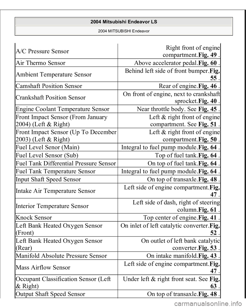
A/C Pressure Sensor
Right front of engine
compartment.Fig. 49
.
Air Thermo Sensor
Above accelerator pedal.Fig. 60
.
Ambient Temperature Sensor
Behind left side of front bumper.Fig.
55 .
Camshaft Position Sensor
Rear of engine.Fig. 46
.
Crankshaft Position Sensor
On front of engine, next to crankshaft
sprocket.Fig. 40
.
Engine Coolant Temperature Sensor
Near throttle body. See Fig. 45
.
Front Impact Sensor (From January
2004) (Left & Right)
Left & right front of engine
compartment. See Fig. 51
.
Front Impact Sensor (Up To December
2003) (Left & Right)
Left & right front of engine
compartment.Fig. 50
.
Fuel Level Senor (Main)
Integral to fuel pump module.Fig. 64
.
Fuel Level Sensor (Sub)
Top of fuel tank.Fig. 64
.
Fuel Tank Differential Pressure Sensor
On top of fuel tank.Fig. 64
.
Fuel Tank Temperature Sensor
Integral to fuel pump module.Fig. 64
.
Input Shaft Speed Sensor
On top of transaxle.Fig. 48
.
Intake Air Temperature Sensor
Left side of engine compartment.Fi
g.
47 .
Interior Temperature Sensor
Left side of dash, right of steering
column.Fig. 61
.
Knock Sensor
Top center of engine.Fig. 41
.
Left Bank Heated Oxygen Sensor
(Front)
On inlet of left catalytic converter.Fi
g.
52 .
Left Bank Heated Oxygen Sensor
(Rear)
On outlet of left bank catalytic
converter.Fig. 53
.
Manifold Absolute Pressure Sensor
On intake manifold.Fig. 43
.
Mass Airflow Sensor
Left side of engine compartment.Fi
g.
47 .
Occupant Classification Sensor (Left
& Right)
Under left & right front seat. See Fi
g.
63 .
Output Shaft Speed Sensor
On top of transaxle.Fig. 48
.
2004 Mitsubishi Endeavor LS
2004 MITSUBISHI Endeavor
Page 1097 of 3870

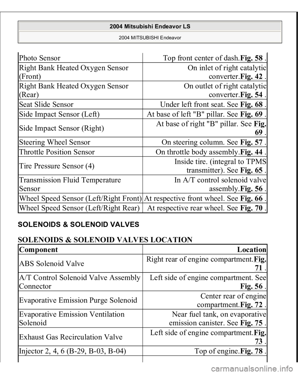
SOLENOIDS & SOLENOID VALVES SOLENOIDS & SOLENOID VALVES LOCATION Photo Sensor
Top front center of dash.Fig. 58
.
Right Bank Heated Oxygen Sensor
(Front)
On inlet of right catalytic
converter.Fig. 42
.
Right Bank Heated Oxygen Sensor
(Rear)
On outlet of right catalytic
converter.Fig. 54
.
Seat Slide Sensor
Under left front seat. See Fig. 68
.
Side Impact Sensor (Left)
At base of left "B" pillar. See Fig. 69
.
Side Impact Sensor (Right)
At base of right "B" pillar. See Fig.
69 .
Steering Wheel Sensor
On steering column. See Fig. 57
.
Throttle Position Sensor
On throttle body assembly.Fig. 44
.
Tire Pressure Sensor (4)
Inside tire. (integral to TPMS
transmitter). See Fig. 65
.
Transmission Fluid Temperature
Sensor
In A/T control solenoid valve
assembly.Fig. 56
.
Wheel Speed Sensor (Left/Right Front)
At respective front wheel. See Fig. 66
.
Wheel Speed Sensor (Left/Right Rear)
At respective rear wheel. See Fig. 70
.
Component
Location
ABS Solenoid Valve
Right rear of engine compartment.Fig.
71 .
A/T Control Solenoid Valve Assembly
Connector
Left side of engine compartment. See
Fig. 56
.
Evaporative Emission Purge Solenoid
Center rear of engine
compartment.Fig. 72
.
Evaporative Emission Ventilation
Solenoid
Near fuel tank, on evaporative
emission canister. See Fig. 75
.
Exhaust Gas Recirculation Valve
Left side of engine compartment.Fig.
73 .
Injector 2, 4, 6 (B-29, B-03, B-04)
Top of engine.Fig. 78
.
2004 Mitsubishi Endeavor LS
2004 MITSUBISHI Endeavor
Page 1524 of 3870

Mixture Check)
Courtesy of MITSUBISHI MOTOR SALES OF AMERICA.
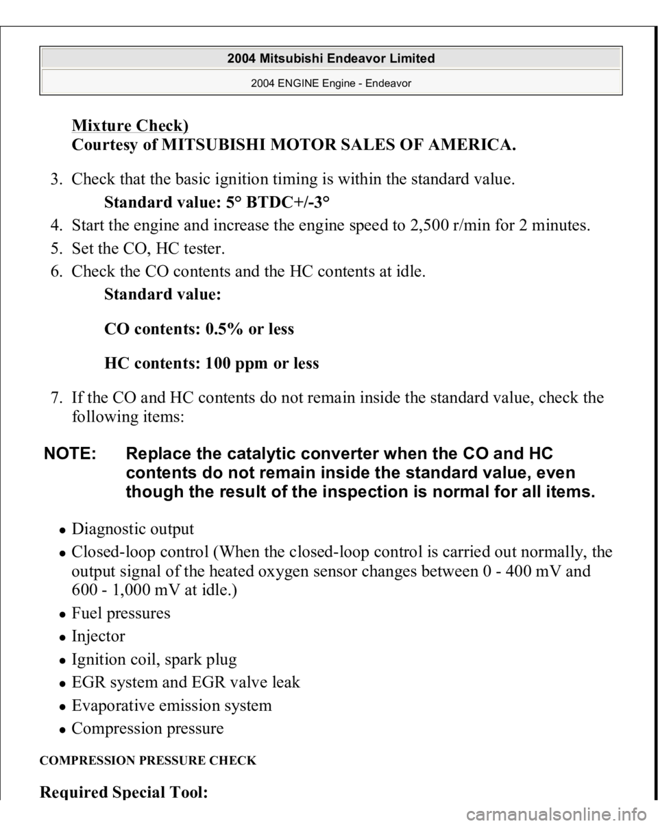
3. Check that the basic ignition timing is within the standard value.
Standard value: 5° BTDC+/-3°
4. Start the engine and increase the engine speed to 2,500 r/min for 2 minutes.
5. Set the CO, HC tester.
6. Check the CO contents and the HC contents at idle.
Standard value:
CO contents: 0.5% or less
HC contents: 100 ppm or less
7. If the CO and HC contents do not remain inside the standard value, check the
following items:
Diagnostic output Closed-loop control (When the closed-loop control is carried out normally, the
output signal of the heated oxygen sensor changes between 0 - 400 mV and
600 - 1,000 mV at idle.) Fuel pressures Injector Ignition coil, spark plug EGR system and EGR valve leak Evaporative emission system Compression pressure
COMPRESSION PRESSURE CHECK Re
quired S
pecial Tool
:
NOTE: Replace the catalytic converter when the CO and HC
contents do not remain inside the standard value, even
though the result of the inspection is normal for all items.
2004 Mitsubishi Endeavor Limited
2004 ENGINE Engine - Endeavor
Page 1528 of 3870
malfunction is a worn or damaged piston ring and/or cylinder inner
surface.
2. If the compression does not rise after oil is added, the cause is a burnt or
defective valve seat, or pressure is leaking from the gasket.
9. Connect the crankshaft position sensor connector.
10. Install the spark plugs and ignition coils.
11. Use the scan tool MB991958 to erase the diagnostic trouble codes.
NOTE: This will erase the diagnostic trouble code resulting from
the crankshaft position sensor connector being
disconnected.
2004 Mitsubishi Endeavor Limited
2004 ENGINE Engine - Endeavor
Page 1999 of 3870

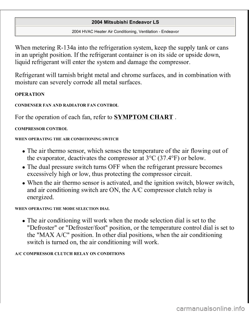
When metering R-134a into the refrigeration system, keep the supply tank or cans
in an upright position. If the refrigerant container is on its side or upside down,
liquid refrigerant will enter the system and damage the compressor.
Refrigerant will tarnish bright metal and chrome surfaces, and in combination with
moisture can severely corrode all metal surfaces. OPERATION CONDENSER FAN AND RADIATOR FAN CONTROL For the operation of each fan, refer to
SYMPTOM CHART
.
COMPRESSOR CONTROL WHEN OPERATING THE AIR CONDITIONING SWITCH
The air thermo sensor, which senses the temperature of the air flowing out of
the evaporator, deactivates the compressor at 3°C (37.4°F) or below. The dual pressure switch turns OFF when the refrigerant pressure becomes
excessively high or low, thus protecting the compressor circuit. When the air thermo sensor is activated, and the ignition switch, blower switch,
and air conditioning switch are ON, the A/C compressor clutch relay is
energized.
WHEN OPERATING THE MODE SELECTION DIAL
The air conditioning will work when the mode selection dial is set to the
"Defroster" or "Defroster/foot" position, or the temperature control dial is set to
the "MAX A/C" position. In other dial positions, when the air conditioning
switch is turned on, the air conditioning will work.
A/C COMPRESSOR CLUTCH RELAY ON CONDITIONS
2004 Mitsubishi Endeavor LS
2004 HVAC Heater Air Conditioning, Ventilation - Endeavor
Page 2051 of 3870
2. Turn the ignition switch to the "ON" position.
3. Check if the DTC is set.
4. Turn the ignition switch to the "LOCK" (OFF) position. Q: Is the check result satisfactory?
YES:
The procedure is complete.
NO:
Return to Step 1 .
Code No. B1031, B1032 A/C Pressure Sensor System Fig. 38: View A/C Pressure Sensor Circuit
Courtes
y of MITSUBISHI MOTOR SALES OF AMERICA
.
2004 Mitsubishi Endeavor LS
2004 HVAC Heater Air Conditioning, Ventilation - Endeavor
Page 2054 of 3870
Fig. 41: Identifying Connectors C
-16 And C
-17
Courtesy of MITSUBISHI MOTOR SALES OF AMERICA.
DTC SET CONDITION
DTC B1031 is set if there is a short circuit in the A/C pressure sensor input
circuit. DTC B1031 or B1032 is set if there is a defective connector connection, or if
there is an open circuit in the harness.
TECHNICAL DESCRIPTION (COMMENT)
2004 Mitsubishi Endeavor LS
2004 HVAC Heater Air Conditioning, Ventilation - Endeavor