2004 MITSUBISHI ENDEAVOR O2 sensors
[x] Cancel search: O2 sensorsPage 1 of 3870

2004 BRAKES
Anti-Lock Braking System (ABS) - Endeavor
GENERAL DESCRIPTION FEATURES The 4ABS ensures directional stability and control during hard braking.
This ABS uses a 4-sensor 4-channel system that controls all four wheels
independently of each other. The basic system is the same as that for the Lancer.
EBD (Electronic Brake-force Distribution system) control has been installed to
provide the ideal braking force for the rear wheels.
EBD CONTROL In ABS, electronic control is used so the rear wheel brake hydraulic pressure during
braking is regulated by rear wheel control solenoid valves in accordance with the
vehicle's rate of deceleration. The front and rear wheel slippages are calculated from
the signals received from the various wheel sensors. EBD control is a control
system which provides a high level of control for both vehicle braking force and
vehicle stability. The system has the following features:
To shorten the harness wires and enhance data transmission reliability,
communication with other ECU is performed over a CAN (Controller Area
Network). Fail-safe function ensures that safety is maintained. Diagnostic function provides improved serviceability. Because the system provides the optimum rear wheel braking force regardless
of vehicle load and the condition of the road surface, the system reduces the
required pedal depression force, particularly when the vehicle is heavily
loaded. Because the duty placed on the front brakes is reduced, the increases in pad
temperature can be controlled during front brake application to improve pad
wear.
2004 Mitsubishi Endeavor LS
2004 BRAKES Anti-Lock Braking System (ABS) - Endeavor
2004 Mitsubishi Endeavor LS
2004 BRAKES Anti-Lock Braking System (ABS) - Endeavor
Page 65 of 3870
Courtesy of MITSUBISHI MOTOR SALES OF AMERICA
.
2. Turn the ignition switch to the "ON" position.
3. Check whether DTC C1200, C1205, C1210 or C1215 have been set.
4. Turn the ignition switch to the "LOCK" (OFF) position.
Q: Is DTC C1200, C1205, C1210 or C1215 set?
YES: Carry out diagnosis relevant to DTC C1200, C1205, C1210 or
C1215 (Refer to DIAGNOSTIC TROUBLE CODE PROCEDURES
).
NO: Go to Step 4.
STEP 4. Check the installation condition of the ABS sensors.
For the ABS sensor, which the DTC code indicates, check whether the sensor
or its mounting bolts are loosened.
DTC C1201 is set: Front right ABS sensor DTC C1206 is set: Front left ABS sensor DTC C1211 is set: Rear right ABS sensor DTC C1216 is set: Rear left ABS sensor
Q: Is the ABS sensor installed correctly?
YES: Go to Step 5.
NO: Reinstall the ABS sensor correctly. Then go to Step 16 .
STEP 5 Check the ABS sensor after it is removed from the vehicle.
Check the ABS sensor, which the DTC code indicates (Refer to
INSPECTION
).
DTC C1201 is set: Front right ABS sensor DTC C1206 is set: Front left ABS sensor DTC C1211 is set: Rear right ABS sensor DTC C1216 is set: Rear left ABS sensor
2004 Mitsubishi Endeavor LS
2004 BRAKES Anti-Lock Braking System (ABS) - Endeavor
Page 273 of 3870
2004 ACCESSORIES/SAFETY EQUIPMENT
Mitsubishi - Air Bag Restraint Systems
DESCRIPTION & OPERATION Supplemental Restraint System (SRS) components on vehicles with single-stage air
bag systems include single-stage driver-side and passenger-side air bag modules,
side impact air bag modules, seat belt pretensioners, front impact sensors, side
impact sensors, SRS Electronic Control Unit (SRS ECU) and an AIR BAG warning
light or SRS warning light.
SRS components on vehicles with dual-stage air bag systems include dual-stage
driver-side and passenger-side air bag modules, side impact air bag modules, seat
belt pretensioners, front impact sensors, side impact sensors, SRS Electronic
Control Unit (SRS ECU), occupant classification sensor, occupant classification
sensor ECU, seat belt switches, AIR BAG warning light or SRS warning light,
PASSENGER AIR BAG OFF warning light and a PASSENGER SEAT BELT
warning light. COMPONENT LOCATIONS Refer to illustration for SRS com
ponent locations. See
Fig. 1
&
Fig. 2
.
WARNING:Accidental air bag deployment is possible. Personal
injury may result. Read and follow all WARNINGS
and AIR BAG SAFETY PRECAUTIONS
before
working on air bag system or related components.
2004 Mitsubishi Endeavor Limited
2004 ACCESSORIES/SAFETY EQUIPMENT Mitsubishi - Air Bag Restraint Systems
2004 Mitsubishi Endeavor Limited
2004 ACCESSORIES/SAFETY EQUIPMENT Mitsubishi - Air Bag Restraint Systems
Page 277 of 3870
Such shorts can damage fuses or components and may cause a second
Diagnostic Trouble Code (DTC) to set, making diagnosis of original problem
more difficult. Never use an analog volt/ohm meter or test light in place of a Digital Volt/Ohm
Meter (DVOM). Use only a DVOM with a maximum test current of 2 mA
(milliamps) at minimum range of resistance measurement. If SRS is not fully functional for any reason, DO NOT drive vehicle until
system is repaired and fully functional. DO NOT remove bulbs, modules,
sensors, or other components or in any way disable system from operating
normally. If SRS is not functional, park vehicle until repairs are made.
DISABLING & ACTIVATING AIR BAG SYSTEM To disable system, turn ignition off. Disconnect negative battery cable. Shield cable
end with electrical tape. Wait at least 60 seconds before servicing air bag system.
To activate system, reconnect negative battery cable. Check system operation. See SYSTEM OPERATION CHECK
.
DISPOSAL PROCEDURES DEPLOYED AIR BAG OR SEAT BELT PRETENSIONER Place deployed component in a strong plastic bag and seal tightly. Dispose of
component as you would any other part. No other special disposal procedure is
required. UNDEPLOYED AIR BAG OR SEAT BELT PRETENSIONER
WARNING:Accidental air bag deployment is possible. Personal
injury may result. Read and follow all WARNINGS
and AIR BAG SAFETY PRECAUTIONS
before
working on air bag system or related components.
NOTE: Undeployed air bag modules must be deployed before
disposal. Disposing of an undeployed air bag may violate
federal, state and/or local laws. This also applies to vehicles
that are to be scrapped.
2004 Mitsubishi Endeavor Limited
2004 ACCESSORIES/SAFETY EQUIPMENT Mitsubishi - Air Bag Restraint Systems
Page 316 of 3870
1. Before proceeding, see AIR BAG SAFETY PRECAUTIONS
. Disable air
bag system. See DISABLING & ACTIVATING AIR BAG SYSTEM
. Go
to next step.
2. Remove front impact sensors. See FRONT IMPACT SENSOR
under
REMOVAL & INSTALLATION. Inspect front impact sensors. See FRONT
IMPACT SENSOR
under COMPONENT TESTING. If front impact sensors
are okay, go to next step. If front impact sensors are not okay, replace front
impact sensors. Go to step 6 .
3. Install front impact sensors. Connect front impact sensor connectors.
Disconnect SRS ECU connector C-26. See SRS ELECTRONIC CONTROL
UNIT (SRS ECU)
under REMOVAL & INSTALLATION. See Fig. 19
.
Measure resistance between SRS connector C-26, terminals No. 3 (Black/Blue
wire) and No. 4 (White/Blue wire). See Fig. 21
. If resistance is 738-902 ohms,
go to next step. If resistance is not 738-902 ohms, check wire harness between
SRS ECU connector C-26 and left front impact sensor connector A-21.
Replace wire harness, if damaged. Go to step 6 .
4. Measure resistance between SRS connector C-26, terminals No. 1 (White/Red
wire) and No. 2 (Black/Red wire). If resistance is not 738-902 ohms, go to next
step. If resistance is 738-902 ohms, replace SRS ECU. Go to step 6
.
5. Inspect wire harness between SRS ECU connector C-26 and right front impact
sensor connector A-27. If wire harness is okay, go to next step. Replace wire
harness, if damaged. Go to next step.
6. Reconnect SRS components. Activate air bag system. Using scan tool, check
for DTCs. If DTCs 11, 12 or 13 are retrieved by scan tool, go to step 1 . If
DTCs 11, 12 or 13 are not retrieved by scan tool, system is normal at this time.
Intermittent condition may exist.
DTC 14: ANALOG "G" SENSOR SYSTEM If DTC 14 is present, replace SRS ECU. See SRS ELECTRONIC CONTROL UNIT (SRS ECU)
under REMOVAL & INSTALLATION.
DTC 15, 16, 17: SAFING SENSOR CIRCUIT If DTC 15, 16 or 17 is present, replace SRS ECU. See SRS ELECTRONIC CONTROL UNIT
(SRS ECU
)under REMOVAL & INSTALLATION.
2004 Mitsubishi Endeavor Limited
2004 ACCESSORIES/SAFETY EQUIPMENT Mitsubishi - Air Bag Restraint Systems
Page 813 of 3870
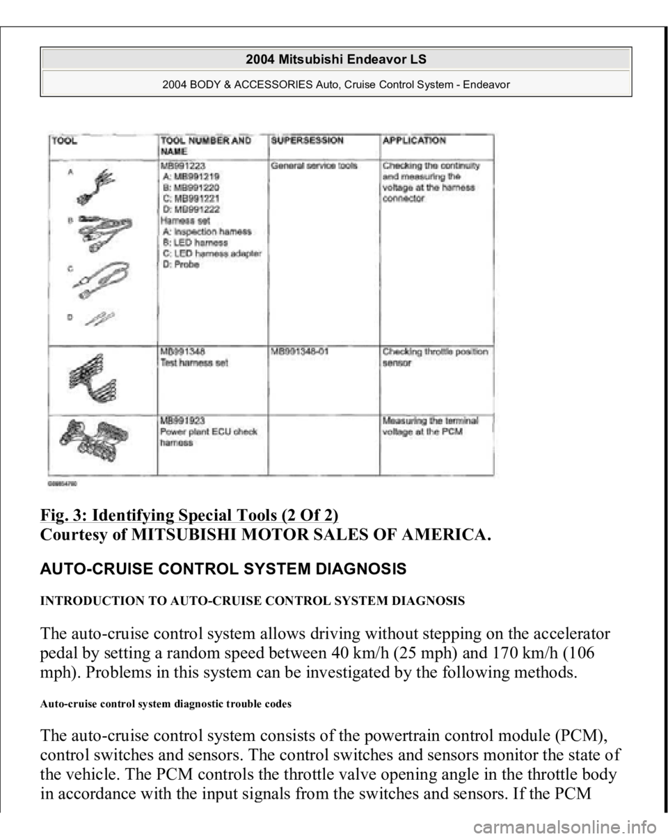
Fig. 3: Identifying Special Tools (2 Of 2)
Courtesy of MITSUBISHI MOTOR SALES OF AMERICA.
AUTO-CRUISE CONTROL SYSTEM DIAGNOSIS INTRODUCTION TO AUTO-CRUISE CONTROL SYSTEM DIAGNOSIS The auto-cruise control system allows driving without stepping on the accelerator
pedal by setting a random speed between 40 km/h (25 mph) and 170 km/h (106
mph). Problems in this system can be investigated by the following methods. Auto-cruise control system diagnostic trouble codes The auto-cruise control system consists of the powertrain control module (PCM),
control switches and sensors. The control switches and sensors monitor the state of
the vehicle. The PCM controls the throttle valve opening angle in the throttle body
in accordance with the in
put si
gnals from the switches and sensors. If the PCM
2004 Mitsubishi Endeavor LS
2004 BODY & ACCESSORIES Auto, Cruise Control System - Endeavor
Page 1095 of 3870
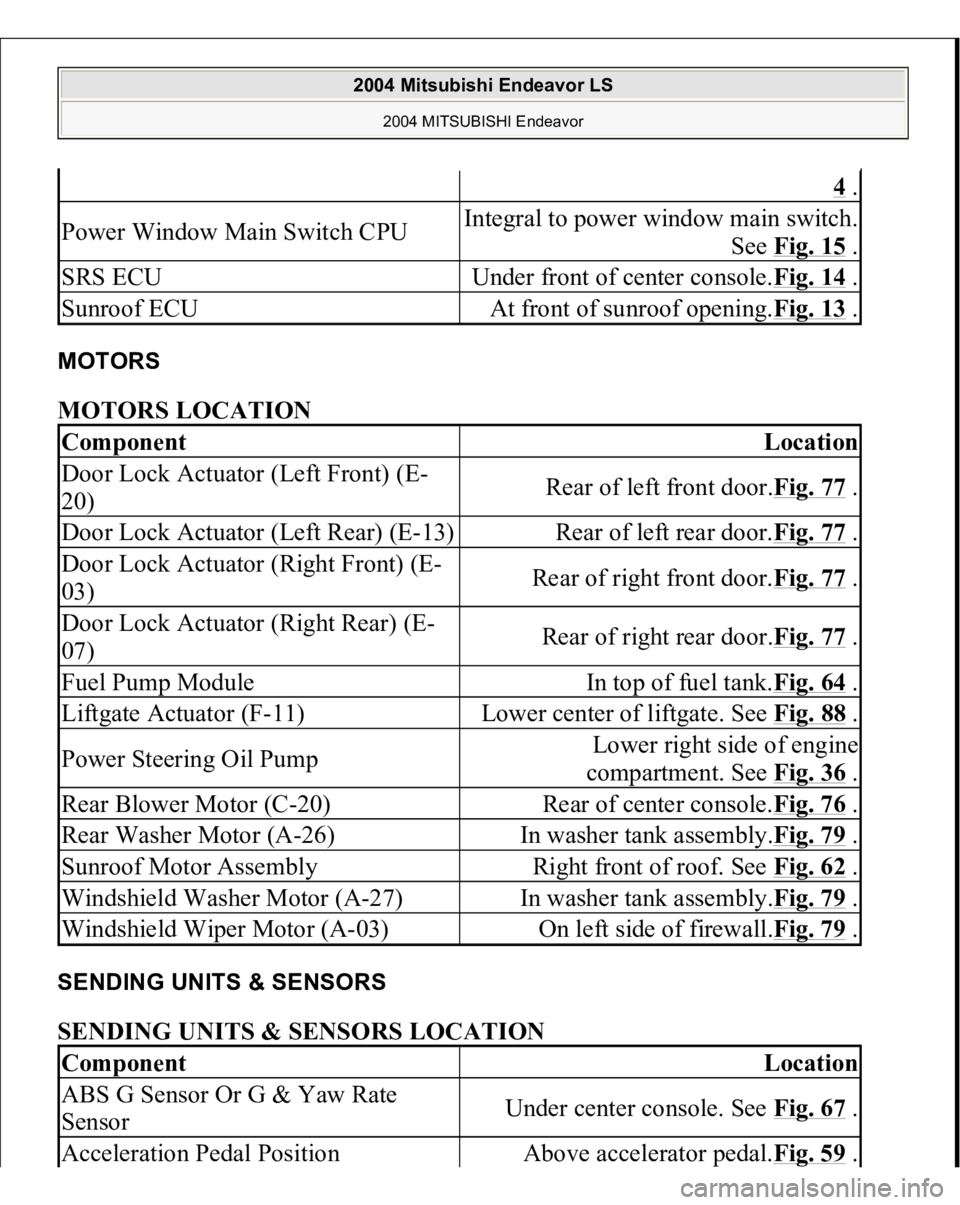
MOTORS MOTORS LOCATION SENDING UNITS & SENSORS SENDING UNITS & SENSORS LOCATION
4 .
Power Window Main Switch CPU
Integral to power window main switch.
See Fig. 15
.
SRS ECU
Under front of center console.Fig. 14
.
Sunroof ECU
At front of sunroof opening.Fig. 13
.
Component
Location
Door Lock Actuator (Left Front) (E-
20)
Rear of left front door.Fig. 77
.
Door Lock Actuator (Left Rear) (E-13)
Rear of left rear door.Fig. 77
.
Door Lock Actuator (Right Front) (E-
03)
Rear of right front door.Fig. 77
.
Door Lock Actuator (Right Rear) (E-
07)
Rear of right rear door.Fig. 77
.
Fuel Pump Module
In top of fuel tank.Fig. 64
.
Liftgate Actuator (F-11)
Lower center of liftgate. See Fig. 88
.
Power Steering Oil Pump
Lower right side of engine
compartment. See Fig. 36
.
Rear Blower Motor (C-20)
Rear of center console.Fig. 76
.
Rear Washer Motor (A-26)
In washer tank assembly.Fig. 79
.
Sunroof Motor Assembly
Right front of roof. See Fig. 62
.
Windshield Washer Motor (A-27)
In washer tank assembly.Fig. 79
.
Windshield Wiper Motor (A-03)
On left side of firewall.Fig. 79
.
Component
Location
ABS G Sensor Or G & Yaw Rate
Sensor
Under center console. See Fig. 67
.
Acceleration Pedal Position
Above accelerator pedal.Fig. 59
.
2004 Mitsubishi Endeavor LS
2004 MITSUBISHI Endeavor
Page 1147 of 3870
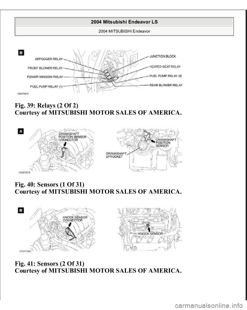
Fig. 39: Relays (2 Of 2)
Courtesy of MITSUBISHI MOTOR SALES OF AMERICA.
Fig. 40: Sensors (1 Of 31)
Courtesy of MITSUBISHI MOTOR SALES OF AMERICA.
Fig. 41: Sensors (2 Of 31)
Courtesy of MITSUBISHI MOTOR SALES OF AMERICA.
2004 Mitsubishi Endeavor LS
2004 MITSUBISHI Endeavor