Page 253 of 3870

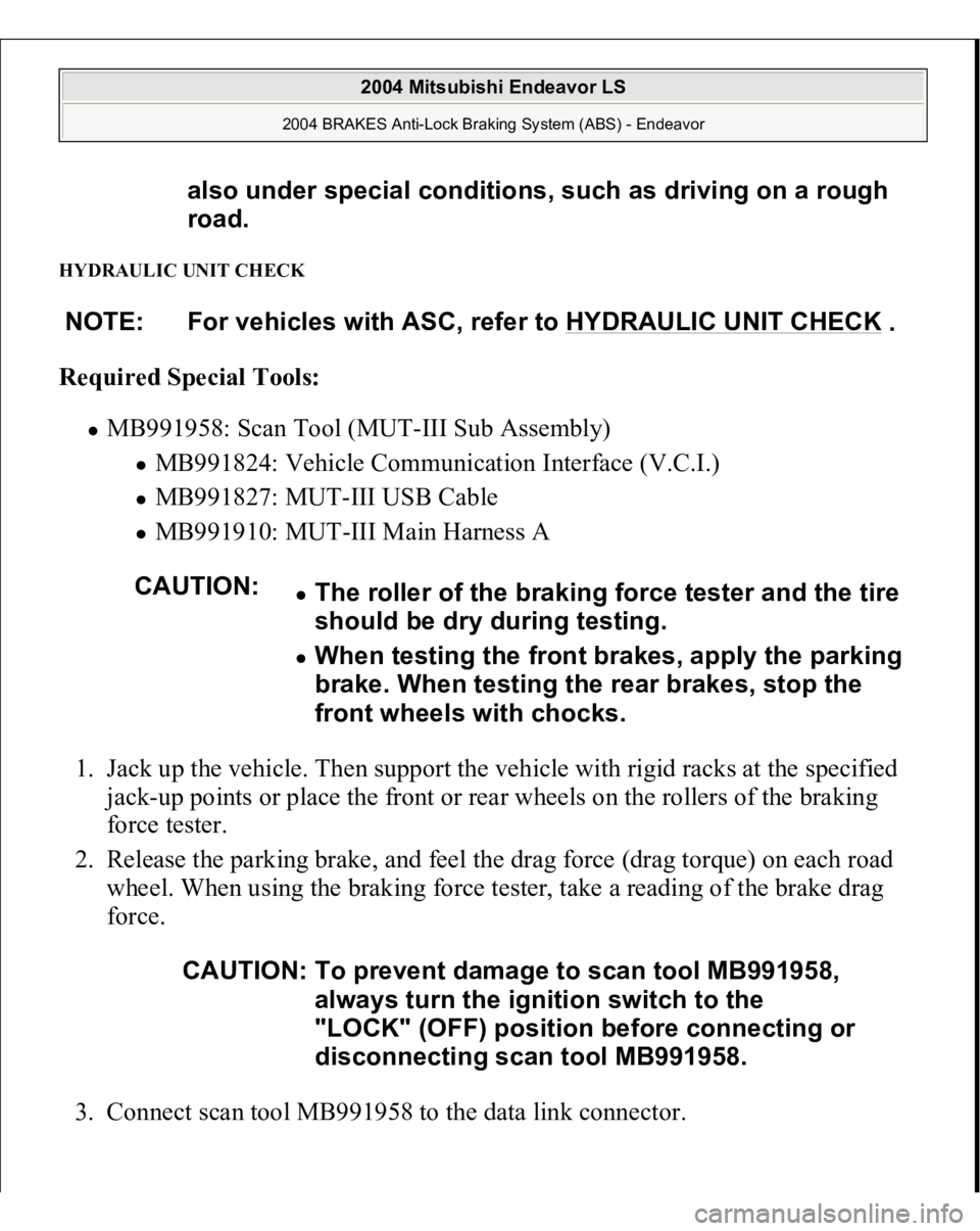
HYDRAULIC UNIT CHECK Required Special Tools:
MB991958: Scan Tool (MUT-III Sub Assembly)
MB991824: Vehicle Communication Interface (V.C.I.) MB991827: MUT-III USB Cable MB991910: MUT-III Main Harness A
1. Jack up the vehicle. Then support the vehicle with rigid racks at the specified
jack-up points or place the front or rear wheels on the rollers of the braking
force tester.
2. Release the parking brake, and feel the drag force (drag torque) on each road
wheel. When using the braking force tester, take a reading of the brake drag
force.
3. Connect scan tool MB991958 to the data link connec
tor. also under special conditions, such as driving on a rough
road.
NOTE: For vehicles with ASC, refer to HYDRAULIC UNIT CHECK
.
CAUTION:
The roller of the braking force tester and the tire
should be dry during testing. When testing the front brakes, apply the parking
brake. When testing the rear brakes, stop the
front wheels with chocks.
CAUTION: To prevent damage to scan tool MB991958,
always turn the ignition switch to the
"LOCK" (OFF) position before connecting or
disconnecting scan tool MB991958.
2004 Mitsubishi Endeavor LS
2004 BRAKES Anti-Lock Braking System (ABS) - Endeavor
Page 281 of 3870

When a vehicle has been involved in a collision, certain components of the passive
restraint system must be inspected or replaced. See
AIR BAG/SRS
COMPONENT INSPECTION & REPLACEMENT TABLES
article in the
GENERAL INFORMATION section.
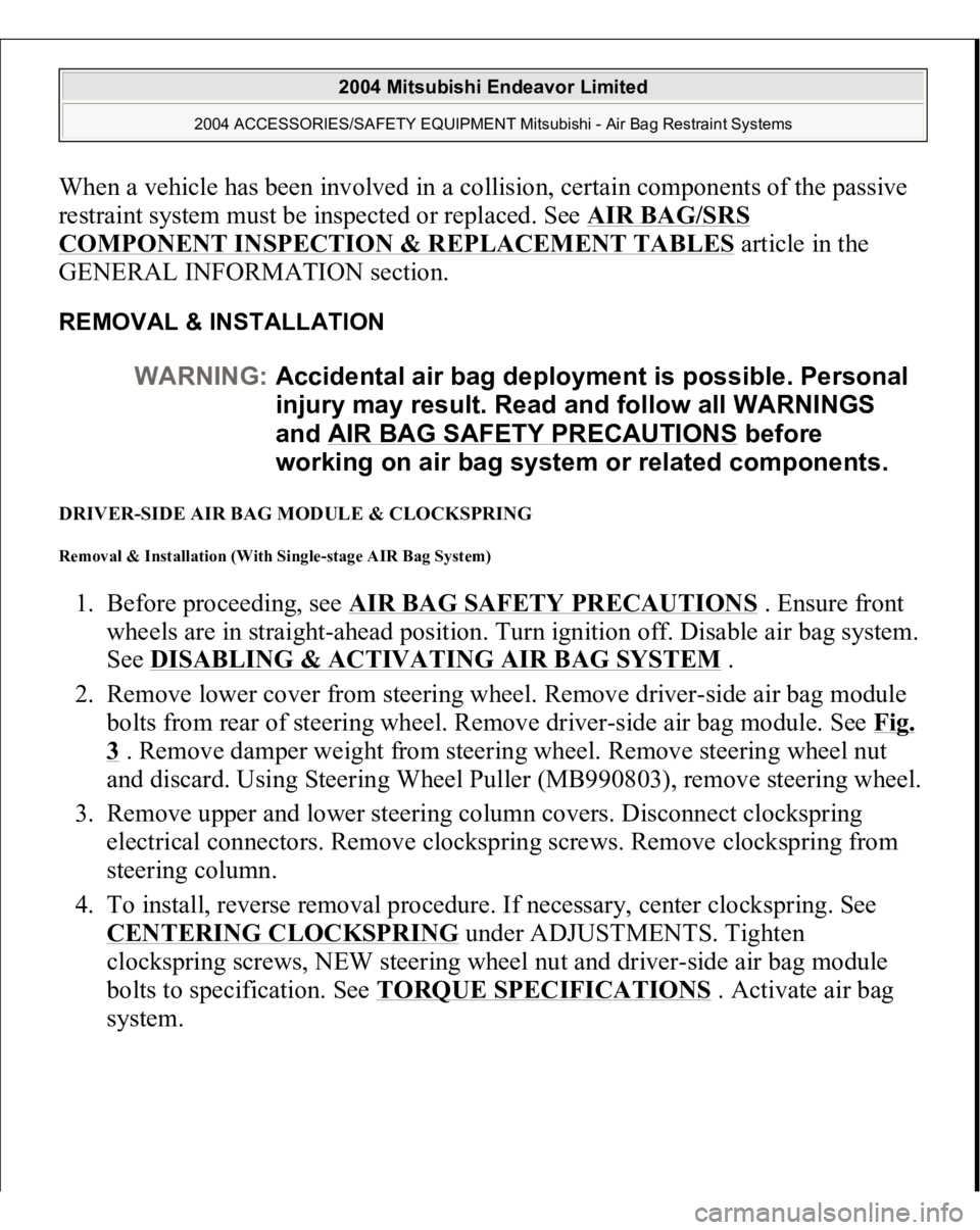
REMOVAL & INSTALLATION DRIVER-SIDE AIR BAG MODULE & CLOCKSPRING Removal & Installation (With Single-stage AIR Bag System) 1. Before proceeding, see
AIR BAG SAFETY PRECAUTIONS
. Ensure front
wheels are in straight-ahead position. Turn ignition off. Disable air bag system.
See
DISABLING & ACTIVATING AIR BAG SYSTEM
.
2. Remove lower cover from steering wheel. Remove driver-side air bag module
bolts from rear of steering wheel. Remove driver-side air bag module. See
Fig.
3 . Remove damper weight from steering wheel. Remove steering wheel nut
and discard. Using Steering Wheel Puller (MB990803), remove steering wheel.
3. Remove upper and lower steering column covers. Disconnect clockspring
electrical connectors. Remove clockspring screws. Remove clockspring from
steering column.
4. To install, reverse removal procedure. If necessary, center clockspring. See CENTERING CLOCKSPRING
under ADJUSTMENTS. Tighten
clockspring screws, NEW steering wheel nut and driver-side air bag module
bolts to specification. See
TORQUE SPECIFICATIONS
. Activate air bag
s
ystem. WARNING:Accidental air bag deployment is possible. Personal
injury may result. Read and follow all WARNINGS
and AIR BAG SAFETY PRECAUTIONS
before
working on air bag system or related components.
2004 Mitsubishi Endeavor Limited
2004 ACCESSORIES/SAFETY EQUIPMENT Mitsubishi - Air Bag Restraint Systems
Page 283 of 3870
steering column.
4. To install, reverse removal procedure. If necessary, center clockspring. See
CENTERING CLOCKSPRING
under ADJUSTMENTS. Tighten
clockspring screws, NEW steering wheel nut and driver-side air bag module
bolts to specification. See TORQUE SPECIFICATIONS
. Activate air bag
system.
Fig. 4: Identifying Driver
-side Air Bag Module & Clockspring (Dual
-stage Air
Bag System)
Courtesy of MITSUBISHI MOTOR SALES OF AMERICA.
FLOOR CONSOLE ASSEMBLY (WITH DUAL STAGE AIR BAG SYSTEM) Removal & Installation 1. Before proceeding, see AIR BAG SAFETY PRECAUTIONS
. Disable air
bag system. See DISABLING & ACTIVATING AIR BAG SYSTEM
.
2. Remove inner box tray. See Fig. 5
. Remove plate. Remove cup holder,
Remove left and right side covers. Remove gearshift lever panel. Remove
accessory panel. Remove rear A/C switch and accessory socket. Remove floor
console assembl
y.
2004 Mitsubishi Endeavor Limited
2004 ACCESSORIES/SAFETY EQUIPMENT Mitsubishi - Air Bag Restraint Systems
Page 285 of 3870
2. Disconnect appropriate front impact sensor connector. Disconnect electrical
sensor. Remove front impact sensor nuts. Remove front impact sensor. See
Fig. 6
or Fig. 7
.
3. To install, reverse removal procedure. Tighten front impact sensor nuts to
specification. See TORQUE SPECIFICATIONS
. Activate air bag system.
Fig. 6: Identifying Front Impact Sensor (Single
-stage Air Bag System)
Courtesy of MITSUBISHI MOTOR SALES OF AMERICA.
2004 Mitsubishi Endeavor Limited
2004 ACCESSORIES/SAFETY EQUIPMENT Mitsubishi - Air Bag Restraint Systems
Page 289 of 3870

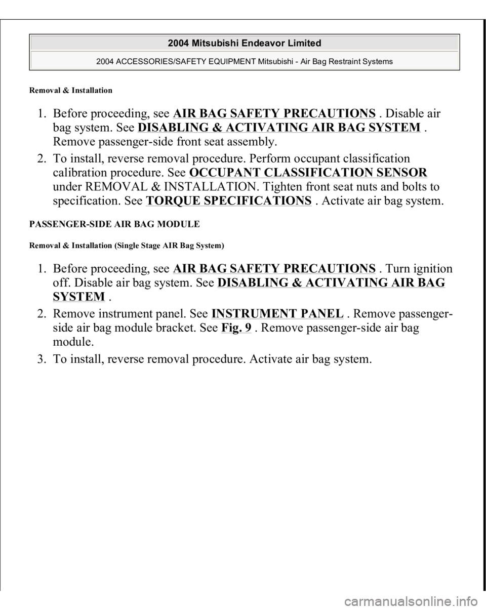
Removal & Installation 1. Before proceeding, see AIR BAG SAFETY PRECAUTIONS
. Disable air
bag system. See DISABLING & ACTIVATING AIR BAG SYSTEM
.
Remove passenger-side front seat assembly.
2. To install, reverse removal procedure. Perform occupant classification
calibration procedure. See OCCUPANT CLASSIFICATION SENSOR
under REMOVAL & INSTALLATION. Tighten front seat nuts and bolts to
specification. See TORQUE SPECIFICATIONS
. Activate air bag system.
PASSENGER-SIDE AIR BAG MODULE Removal & Installation (Single Stage AIR Bag System) 1. Before proceeding, see AIR BAG SAFETY PRECAUTIONS
. Turn ignition
off. Disable air bag system. See DISABLING & ACTIVATING AIR BAG
SYSTEM
.
2. Remove instrument panel. See INSTRUMENT PANEL
. Remove passenger-
side air bag module bracket. See Fig. 9
. Remove passenger-side air bag
module.
3. To install, reverse removal
procedure. Activate ai
r ba
g system.
2004 Mitsubishi Endeavor Limited
2004 ACCESSORIES/SAFETY EQUIPMENT Mitsubishi - Air Bag Restraint Systems
Page 291 of 3870
Fig. 10: Identifying Passenger
-side Air Bag Module (Dual
-stage Air Bag
System)
Courtesy of MITSUBISHI MOTOR SALES OF AMERICA.
SEAT BELT PRETENSIONER (DUAL STAGE AIR BAG SYSTEM) Removal & Installation (Single Stage AIR Bag System) 1. Before proceeding, see AIR BAG SAFETY PRECAUTIONS
. Disable air
bag system. See DISABLING & ACTIVATING AIR BAG SYSTEM
.
2. Remove appropriate upper anchor bolt cover. See Fig. 11
. Remove upper
anchor bolt. Remove lower anchor bolt. Remove lower B-pillar trim panel.
Disconnect seat belt pretensioner electrical connector. Remove seat belt
pretensioner retaining bolt. Remove seat belt pretensioner.
3. To install, reverse removal procedure. Tighten seat belt pretensioner anchor
bolts to specification. See TORQUE SPECIFICATIONS . Activate air bag
s
ystem.
2004 Mitsubishi Endeavor Limited
2004 ACCESSORIES/SAFETY EQUIPMENT Mitsubishi - Air Bag Restraint Systems
Page 293 of 3870
See OCCUPANT CLASSIFICATION SENSOR CALIBRATION
under
COMPONENT TESTING. Tighten seat belt pretensioner anchor bolts to
specification. See TORQUE SPECIFICATIONS
. Activate air bag system.
Fig. 12: Identifying Passenger Seat Slide Adjuster Rear Cover (Dual
-stage Air
Bag System)
Courtesy of MITSUBISHI MOTOR SALES OF AMERICA.
SEAT SLIDE SENSOR (DUAL STAGE AIR BAG SYSTEM) Removal & Installation 1. Before proceeding, see AIR BAG SAFETY PRECAUTIONS
. Disable air
bag system. See DISABLING & ACTIVATING AIR BAG SYSTEM
.
2. Remove driver seat. Remove seat slide sensor bolt. See Fig. 13
. Remove seat
2004 Mitsubishi Endeavor Limited
2004 ACCESSORIES/SAFETY EQUIPMENT Mitsubishi - Air Bag Restraint Systems
Page 294 of 3870
slide sensor.
3. To install, reverse removal procedure. Tighten seat slide sensor bolt and front
seat bolts to specification. See TORQUE SPECIFICATIONS
. Activate air
bag system.
Fig. 13: Identifying Seat Slide Sensor
Courtesy of MITSUBISHI MOTOR SALES OF AMERICA.
SIDE IMPACT AIR BAG MODULE Removal & Installation 1. Before proceeding, see AIR BAG SAFETY PRECAUTIONS
. Disable air
bag system. See DISABLING & ACTIVATING AIR BAG SYSTEM
.
2. Disconnect wiring under appropriate front seat. Remove seat nuts and bolts.
Remove seat from vehicle. Remove bolts securing seat back assembly to seat
recliner hin
ges. Remove front seat back assembl
y.
NOTE: Side impact air bag module is replaced with seat back
assembly and cannot be serviced separately.
2004 Mitsubishi Endeavor Limited
2004 ACCESSORIES/SAFETY EQUIPMENT Mitsubishi - Air Bag Restraint Systems