2004 MITSUBISHI ENDEAVOR torque
[x] Cancel search: torquePage 3120 of 3870
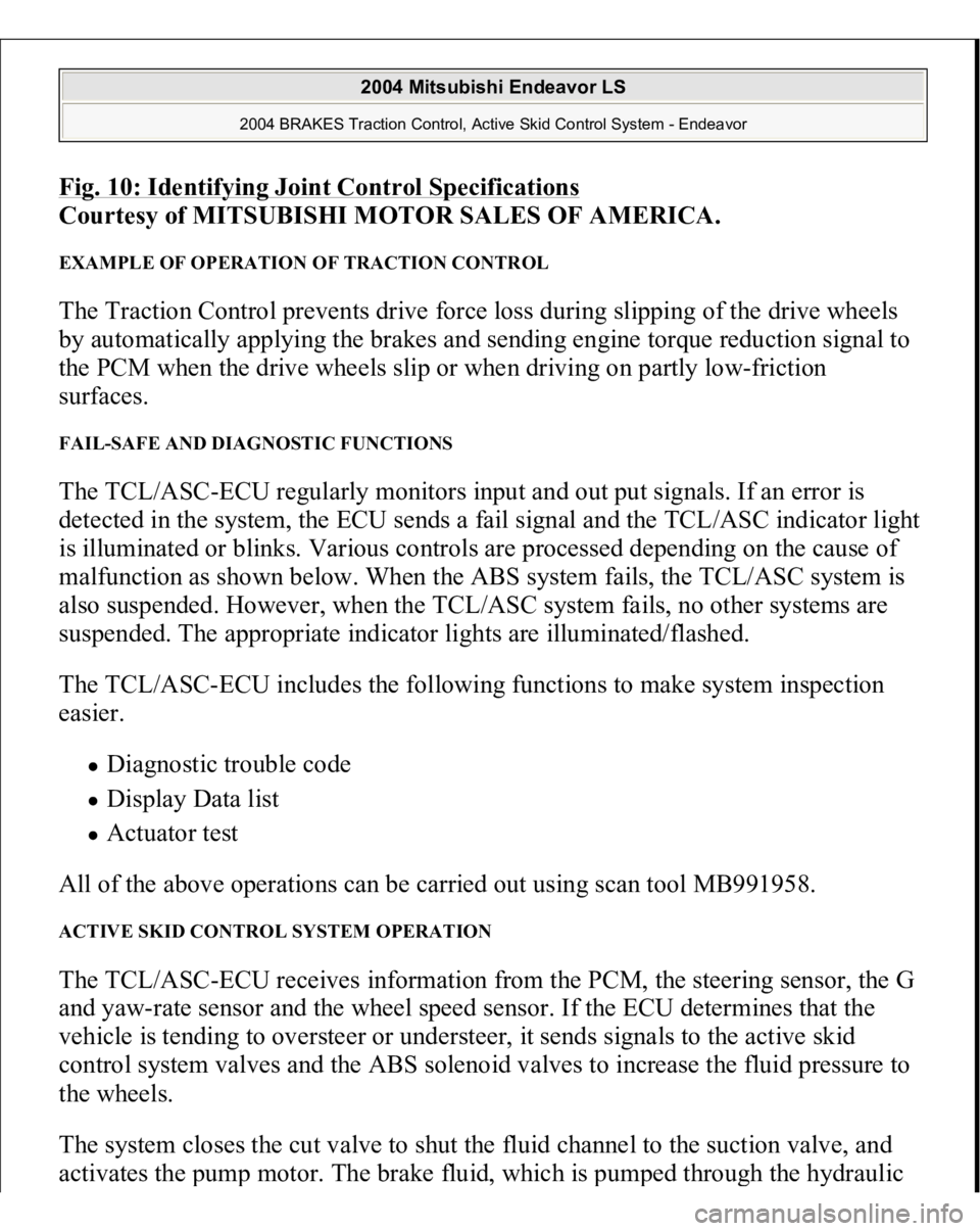
Fig. 10: Identifying Joint Control Specification
s
Courtesy of MITSUBISHI MOTOR SALES OF AMERICA.
EXAMPLE OF OPERATION OF TRACTION CONTROL The Traction Control prevents drive force loss during slipping of the drive wheels
by automatically applying the brakes and sending engine torque reduction signal to
the PCM when the drive wheels slip or when driving on partly low-friction
surfaces. FAIL-SAFE AND DIAGNOSTIC FUNCTIONS The TCL/ASC-ECU regularly monitors input and out put signals. If an error is
detected in the system, the ECU sends a fail signal and the TCL/ASC indicator light
is illuminated or blinks. Various controls are processed depending on the cause of
malfunction as shown below. When the ABS system fails, the TCL/ASC system is
also suspended. However, when the TCL/ASC system fails, no other systems are
suspended. The appropriate indicator lights are illuminated/flashed.
The TCL/ASC-ECU includes the following functions to make system inspection
easier.
Diagnostic trouble code Display Data list Actuator test
All of the above operations can be carried out using scan tool MB991958.
ACTIVE SKID CONTROL SYSTEM OPERATION The TCL/ASC-ECU receives information from the PCM, the steering sensor, the G
and yaw-rate sensor and the wheel speed sensor. If the ECU determines that the
vehicle is tending to oversteer or understeer, it sends signals to the active skid
control system valves and the ABS solenoid valves to increase the fluid pressure to
the wheels.
The system closes the cut valve to shut the fluid channel to the suction valve, and
activates the
pum
p motor. The brake fluid, which is
pum
ped throu
gh the h
ydraulic
2004 Mitsubishi Endeavor LS
2004 BRAKES Traction Control, Active Skid Control System - Endeavor
Page 3134 of 3870
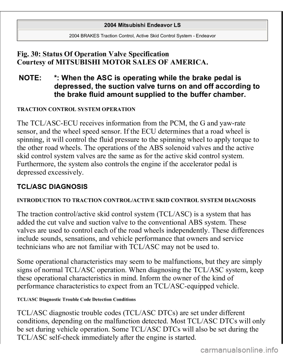
Fig. 30: Status Of Operation Valve Specificatio
n
Courtesy of MITSUBISHI MOTOR SALES OF AMERICA.
TRACTION CONTROL SYSTEM OPERATION The TCL/ASC-ECU receives information from the PCM, the G and yaw-rate
sensor, and the wheel speed sensor. If the ECU determines that a road wheel is
spinning, it will control the fluid pressure to the spinning wheel to apply torque to
the other road wheels. The operations of the ABS solenoid valves and the active
skid control system valves are the same as for the active skid control system.
Furthermore, the system also controls the engine if the accelerator pedal is
depressed excessively. TCL/ASC DIAGNOSIS INTRODUCTION TO TRACTION CONTROL/ACTIVE SKID CONTROL SYSTEM DIAGNOSIS The traction control/active skid control system (TCL/ASC) is a system that has
added the cut valve and suction valve to the conventional ABS system. These
valves are used to control each of the road wheels independently. These differences
include sounds, sensations, and vehicle performance that owners and service
technicians who are not familiar with TCL/ASC may not be used to.
Some operational characteristics may seem to be malfunctions, but they are simply
signs of normal TCL/ASC operation. When diagnosing the TCL/ASC system, keep
these operational characteristics in mind. Inform the owner of the kind of
performance characteristics to expect from an TCL/ASC-equipped vehicle. TCL/ASC Diagnostic Trouble Code Detection Conditions TCL/ASC diagnostic trouble codes (TCL/ASC DTCs) are set under different
conditions, depending on the malfunction detected. Most TCL/ASC DTCs will only
be set during vehicle operation. Some TCL/ASC DTCs will also be set during the
TCL/ASC self-check immediatel
y after the en
gine is started.
NOTE: *: When the ASC is operating while the brake pedal is
depressed, the suction valve turns on and off according to
the brake fluid amount supplied to the buffer chamber.
2004 Mitsubishi Endeavor LS
2004 BRAKES Traction Control, Active Skid Control System - Endeavor
Page 3514 of 3870
1. Jack up the vehicle. Then support the vehicle with rigid racks at the specified
jack-up points or place the front or rear wheels on the rollers of the braking
force tester.
2. Release the parking brake, and feel the drag force (drag torque) on each road
wheel. When using the braking force tester, take a reading of the brake drag
force.
3. Connect scan tool MB991958 to the data link connec
tor. CAUTION:
The roller of the braking force tester and the tire
should be dry during testing. When testing the front brakes, apply the parking
brake. When testing the rear brakes, stop the
front wheels with chocks.
CAUTION: To prevent damage to scan tool MB991958,
always turn the ignition switch to the
"LOCK" (OFF) position before connecting or
disconnecting scan tool MB991958.
2004 Mitsubishi Endeavor LS
2004 BRAKES Traction Control, Active Skid Control System - Endeavor
Page 3552 of 3870
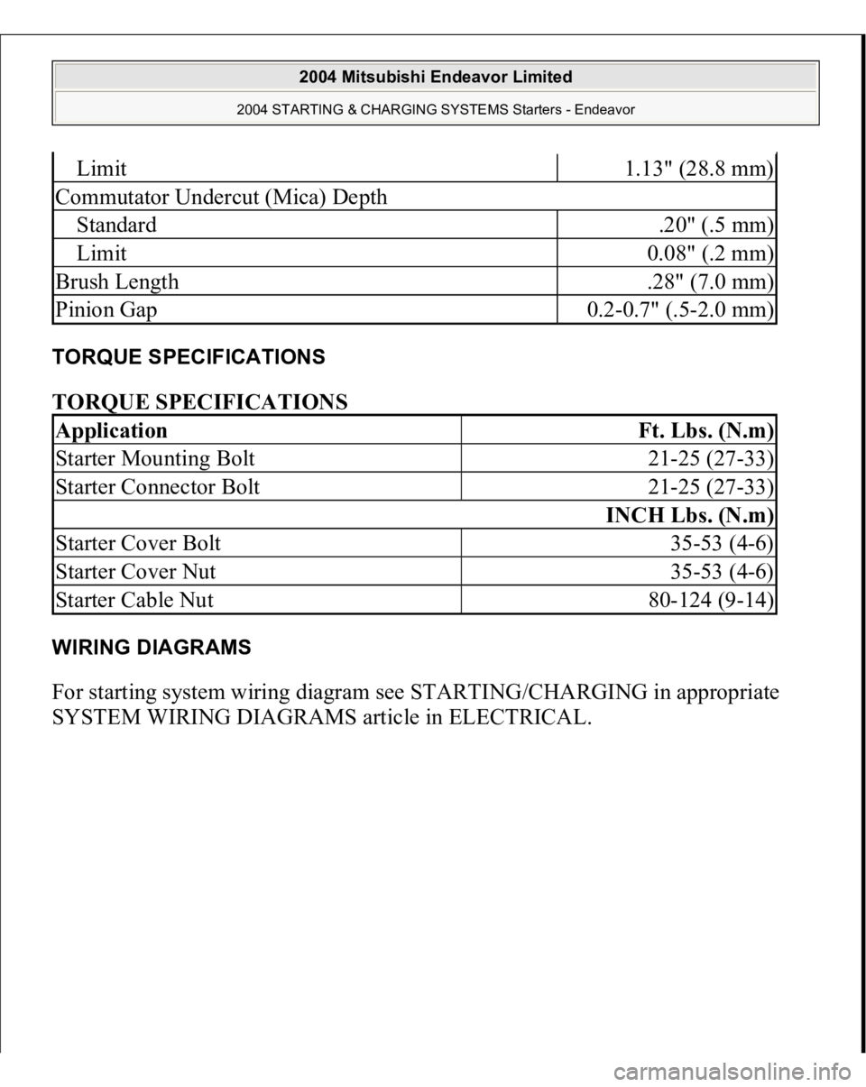
TORQUE SPECIFICATIONS TORQUE SPECIFICATIONS WIRING DIAGRAMS For starting system wiring diagram see STARTING/CHARGING in appropriate
SYSTEM WIRING DIAGRAMS article in ELECTRICAL.
Limit
1.13" (28.8 mm)
Commutator Undercut (Mica) DepthStandard
.20" (.5 mm)
Limit
0.08" (.2 mm)
Brush Length
.28" (7.0 mm)
Pinion Gap
0.2-0.7" (.5-2.0 mm)
Application
Ft. Lbs. (N.m)
Starter Mounting Bolt
21-25 (27-33)
Starter Connector Bolt
21-25 (27-33)
INCH Lbs. (N.m)
Starter Cover Bolt
35-53 (4-6)
Starter Cover Nut
35-53 (4-6)
Starter Cable Nut
80-124 (9-14)
2004 Mitsubishi Endeavor Limited
2004 STARTING & CHARGING SYSTEMS Starters - Endeavor
Page 3577 of 3870
Courtesy of MITSUBISHI MOTOR SALES OF AMERICA
.
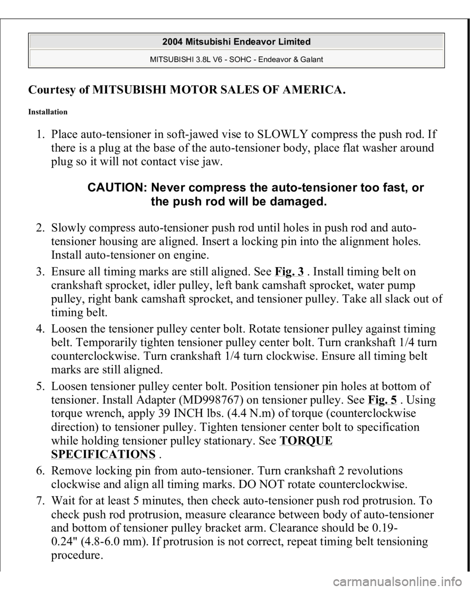
Installation 1. Place auto-tensioner in soft-jawed vise to SLOWLY compress the push rod. If
there is a plug at the base of the auto-tensioner body, place flat washer around
plug so it will not contact vise jaw.
2. Slowly compress auto-tensioner push rod until holes in push rod and auto-
tensioner housing are aligned. Insert a locking pin into the alignment holes.
Install auto-tensioner on engine.
3. Ensure all timing marks are still aligned. See Fig. 3
. Install timing belt on
crankshaft sprocket, idler pulley, left bank camshaft sprocket, water pump
pulley, right bank camshaft sprocket, and tensioner pulley. Take all slack out o
f
timing belt.
4. Loosen the tensioner pulley center bolt. Rotate tensioner pulley against timing
belt. Temporarily tighten tensioner pulley center bolt. Turn crankshaft 1/4 turn
counterclockwise. Turn crankshaft 1/4 turn clockwise. Ensure all timing belt
marks are still aligned.
5. Loosen tensioner pulley center bolt. Position tensioner pin holes at bottom of
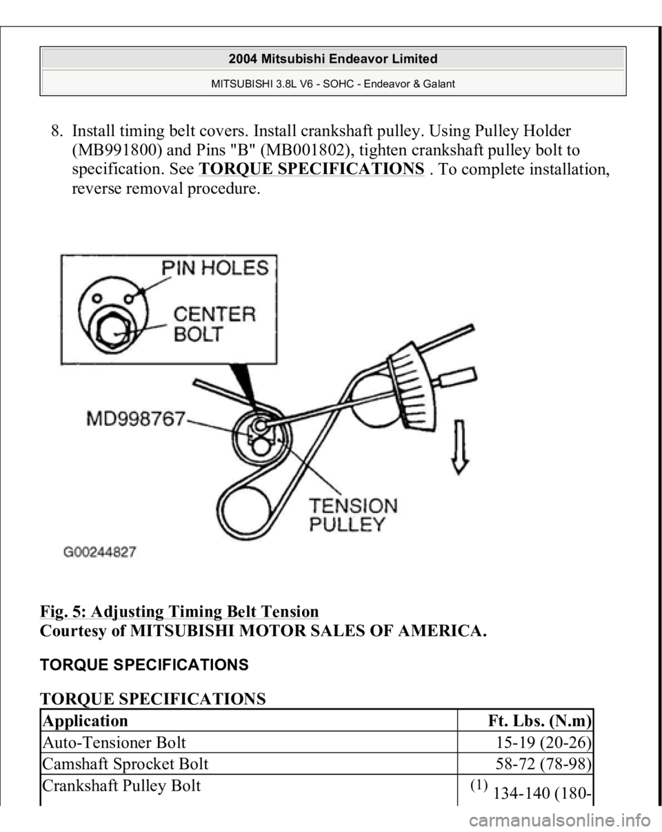
tensioner. Install Adapter (MD998767) on tensioner pulley. See Fig. 5
. Using
torque wrench, apply 39 INCH lbs. (4.4 N.m) of torque (counterclockwise
direction) to tensioner pulley. Tighten tensioner center bolt to specification
while holding tensioner pulley stationary. See TORQUE
SPECIFICATIONS
.
6. Remove locking pin from auto-tensioner. Turn crankshaft 2 revolutions
clockwise and align all timing marks. DO NOT rotate counterclockwise.
7. Wait for at least 5 minutes, then check auto-tensioner push rod protrusion. To
check push rod protrusion, measure clearance between body of auto-tensioner
and bottom of tensioner pulley bracket arm. Clearance should be 0.19-
0.24" (4.8-6.0 mm). If protrusion is not correct, repeat timing belt tensioning
procedure. CAUTION: Never compress the auto-tensioner too fast, or
the push rod will be damaged.
2004 Mitsubishi Endeavor Limited MITSUBISHI 3.8L V6 - SOHC - Endeavor & Galant
Page 3578 of 3870
8. Install timing belt covers. Install crankshaft pulley. Using Pulley Holder
(MB991800) and Pins "B" (MB001802), tighten crankshaft pulley bolt to
specification. See TORQUE SPECIFICATIONS
. To complete installation,
reverse removal procedure.
Fig. 5: Adjusting Timing Belt Tension
Courtesy of MITSUBISHI MOTOR SALES OF AMERICA.
TORQUE SPECIFICATIONS TORQUE SPECIFICATIONS Application
Ft. Lbs. (N.m)
Auto-Tensioner Bolt
15-19 (20-26)
Camshaft Sprocket Bolt
58-72 (78-98)
Crankshaft Pulley Bolt
(1) 134-140 (180-
2004 Mitsubishi Endeavor Limited MITSUBISHI 3.8L V6 - SOHC - Endeavor & Galant
Page 3596 of 3870
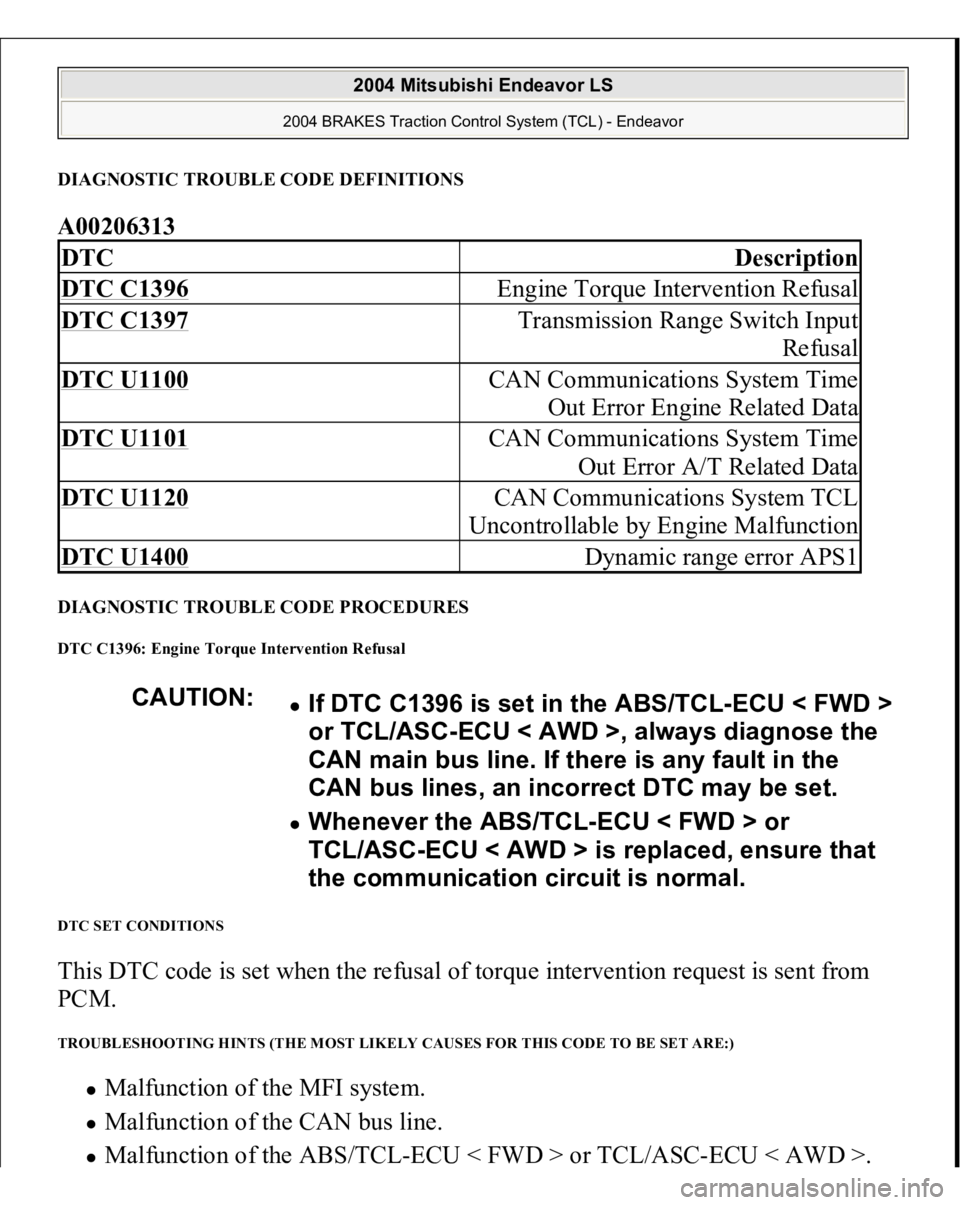
DIAGNOSTIC TROUBLE CODE DEFINITIONSA00206313 DIAGNOSTIC TROUBLE CODE PROCEDURES DTC C1396: Engine Torque Intervention Refusal DTC SET CONDITIONS This DTC code is set when the refusal of torque intervention request is sent from
PCM. TROUBLESHOOTING HINTS (THE MOST LIKELY CAUSES FOR THIS CODE TO BE SET ARE:)
Malfunction of the MFI system. Malfunction of the CAN bus line. Malfunction of the ABS/TC
L-ECU < FWD > or TCL/ASC-ECU < AWD >.
DTC
Description
DTC C1396
Engine Torque Intervention Refusal
DTC C1397
Transmission Range Switch Input
Refusal
DTC U1100
CAN Communications System Time
Out Error Engine Related Data
DTC U1101
CAN Communications System Time
Out Error A/T Related Data
DTC U1120
CAN Communications System TCL
Uncontrollable by Engine Malfunction
DTC U1400
Dynamic range error APS1
CAUTION:
If DTC C1396 is set in the ABS/TCL-ECU < FWD >
or TCL/ASC-ECU < AWD >, always diagnose the
CAN main bus line. If there is any fault in the
CAN bus lines, an incorrect DTC may be set. Whenever the ABS/TCL-ECU < FWD > or
TCL/ASC-ECU < AWD > is replaced, ensure that
the communication circuit is normal.
2004 Mitsubishi Endeavor LS
2004 BRAKES Traction Control System (TCL) - Endeavor
Page 3716 of 3870
![MITSUBISHI ENDEAVOR 2004 Service Repair Manual 2004 Mitsubishi ENDEAVOR 04 - Body > STRUCTURE : BODY [Part 162000 ]
TSB No: 94 NHTSA ID: , June 01, 2003 : Replacement:
Summary: wind deflector installation to reduce wind turbulence inside the ve MITSUBISHI ENDEAVOR 2004 Service Repair Manual 2004 Mitsubishi ENDEAVOR 04 - Body > STRUCTURE : BODY [Part 162000 ]
TSB No: 94 NHTSA ID: , June 01, 2003 : Replacement:
Summary: wind deflector installation to reduce wind turbulence inside the ve](/manual-img/19/57105/w960_57105-3715.png)
2004 Mitsubishi ENDEAVOR 04 - Body > STRUCTURE : BODY [Part 162000 ]
TSB No: 94 NHTSA ID: , June 01, 2003 : Replacement:
Summary: wind deflector installation to reduce wind turbulence inside the vehicle when
driving with the sunroof open. *tt
2004 Mitsubishi ENDEAVOR 04 - Radio CD Player > EQUIPMENT : ELECTRICAL :
RADIO/TAPE DECK/CD ETC. [Part 353400 ]
TSB No: 0354005 NHTSA ID: , May 01, 2003 : Replacement:
Summary: improper alignment between the cd player and the cd opening on the center
instrument panel may cause difficulty ejecting cds. *tt
2004 Mitsubishi ENDEAVOR 04 - Tires > TIRES [Part 190000 ]
TSB No: 93 NHTSA ID: , May 01, 2003 : Replacement:
Summary: tire pressure monitoring system (tpms). *tt
2004 Mitsubishi ENDEAVOR 04 - Body > STRUCTURE : BODY [Part 162000 ]
TSB No: 93 NHTSA ID: , May 01, 2003 : Replacement:
Summary: undercoating appearance. *tt
2004 Mitsubishi ENDEAVOR 04 - Trailer Hitch > TRAILER HITCHES [Part 210000 ]
TSB No: 0300009 NHTSA ID: , May 01, 2003 : Replacement:
Summary: tow hitch torque specification. *tt
2004 Mitsubishi ENDEAVOR 04 - Electrical System > ELECTRICAL SYSTEM [Part
110000 ]
TSB No: 0352A002 NHTSA ID: , May 01, 2003 : Replacement:
Summary: center instrument panel removal. *tt
2004 Mitsubishi ENDEAVOR 04 - Labels > EQUIPMENT : OTHER : LABELS [Part
355100 ]
TSB No: 93 NHTSA ID: , May 01, 2003 : Replacement:
Summary: immobilizer engine control unit (ecu) serial number sticker. *tt