Page 253 of 3870
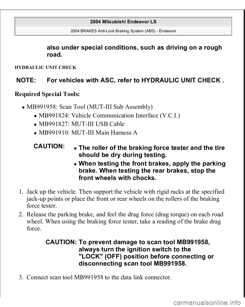
HYDRAULIC UNIT CHECK Required Special Tools:
MB991958: Scan Tool (MUT-III Sub Assembly)
MB991824: Vehicle Communication Interface (V.C.I.) MB991827: MUT-III USB Cable MB991910: MUT-III Main Harness A
1. Jack up the vehicle. Then support the vehicle with rigid racks at the specified
jack-up points or place the front or rear wheels on the rollers of the braking
force tester.
2. Release the parking brake, and feel the drag force (drag torque) on each road
wheel. When using the braking force tester, take a reading of the brake drag
force.
3. Connect scan tool MB991958 to the data link connec
tor. also under special conditions, such as driving on a rough
road.
NOTE: For vehicles with ASC, refer to HYDRAULIC UNIT CHECK
.
CAUTION:
The roller of the braking force tester and the tire
should be dry during testing. When testing the front brakes, apply the parking
brake. When testing the rear brakes, stop the
front wheels with chocks.
CAUTION: To prevent damage to scan tool MB991958,
always turn the ignition switch to the
"LOCK" (OFF) position before connecting or
disconnecting scan tool MB991958.
2004 Mitsubishi Endeavor LS
2004 BRAKES Anti-Lock Braking System (ABS) - Endeavor
Page 281 of 3870
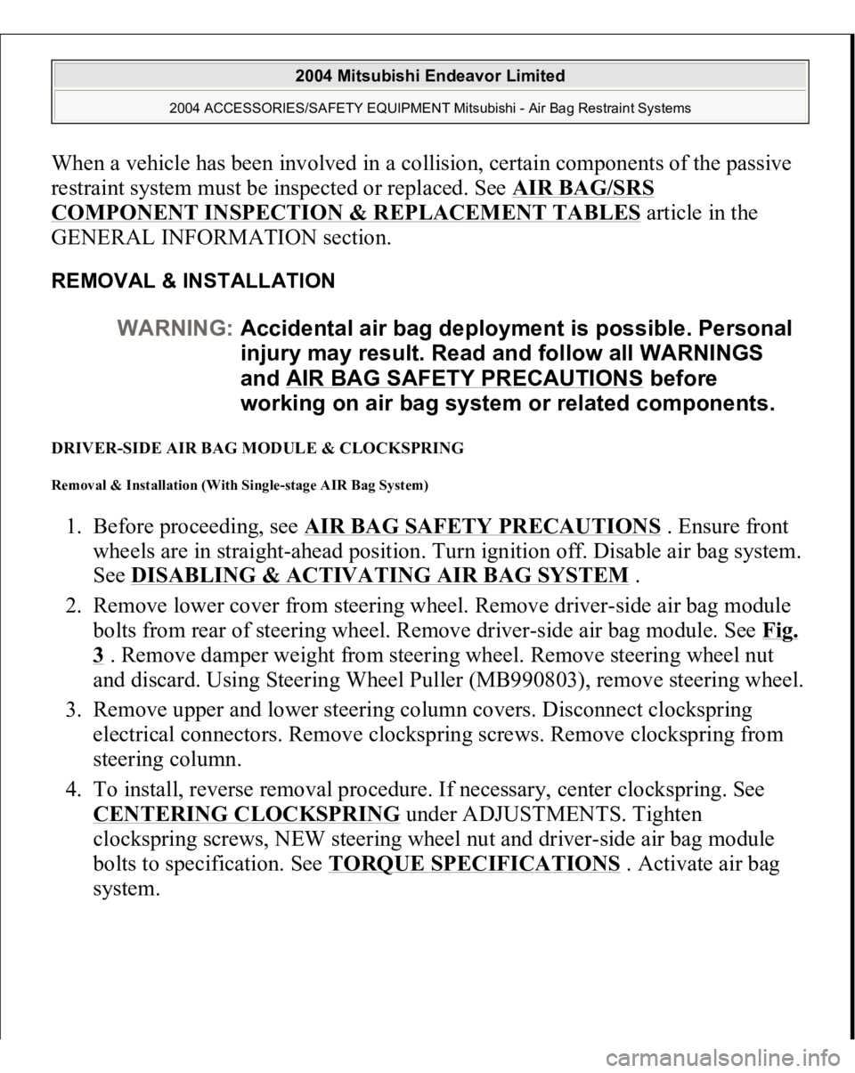
When a vehicle has been involved in a collision, certain components of the passive
restraint system must be inspected or replaced. See
AIR BAG/SRS
COMPONENT INSPECTION & REPLACEMENT TABLES
article in the
GENERAL INFORMATION section.
REMOVAL & INSTALLATION DRIVER-SIDE AIR BAG MODULE & CLOCKSPRING Removal & Installation (With Single-stage AIR Bag System) 1. Before proceeding, see
AIR BAG SAFETY PRECAUTIONS
. Ensure front
wheels are in straight-ahead position. Turn ignition off. Disable air bag system.
See
DISABLING & ACTIVATING AIR BAG SYSTEM
.
2. Remove lower cover from steering wheel. Remove driver-side air bag module
bolts from rear of steering wheel. Remove driver-side air bag module. See
Fig.
3 . Remove damper weight from steering wheel. Remove steering wheel nut
and discard. Using Steering Wheel Puller (MB990803), remove steering wheel.
3. Remove upper and lower steering column covers. Disconnect clockspring
electrical connectors. Remove clockspring screws. Remove clockspring from
steering column.
4. To install, reverse removal procedure. If necessary, center clockspring. See CENTERING CLOCKSPRING
under ADJUSTMENTS. Tighten
clockspring screws, NEW steering wheel nut and driver-side air bag module
bolts to specification. See
TORQUE SPECIFICATIONS
. Activate air bag
s
ystem. WARNING:Accidental air bag deployment is possible. Personal
injury may result. Read and follow all WARNINGS
and AIR BAG SAFETY PRECAUTIONS
before
working on air bag system or related components.
2004 Mitsubishi Endeavor Limited
2004 ACCESSORIES/SAFETY EQUIPMENT Mitsubishi - Air Bag Restraint Systems
Page 283 of 3870
steering column.
4. To install, reverse removal procedure. If necessary, center clockspring. See
CENTERING CLOCKSPRING
under ADJUSTMENTS. Tighten
clockspring screws, NEW steering wheel nut and driver-side air bag module
bolts to specification. See TORQUE SPECIFICATIONS
. Activate air bag
system.
Fig. 4: Identifying Driver
-side Air Bag Module & Clockspring (Dual
-stage Air
Bag System)
Courtesy of MITSUBISHI MOTOR SALES OF AMERICA.
FLOOR CONSOLE ASSEMBLY (WITH DUAL STAGE AIR BAG SYSTEM) Removal & Installation 1. Before proceeding, see AIR BAG SAFETY PRECAUTIONS
. Disable air
bag system. See DISABLING & ACTIVATING AIR BAG SYSTEM
.
2. Remove inner box tray. See Fig. 5
. Remove plate. Remove cup holder,
Remove left and right side covers. Remove gearshift lever panel. Remove
accessory panel. Remove rear A/C switch and accessory socket. Remove floor
console assembl
y.
2004 Mitsubishi Endeavor Limited
2004 ACCESSORIES/SAFETY EQUIPMENT Mitsubishi - Air Bag Restraint Systems
Page 299 of 3870
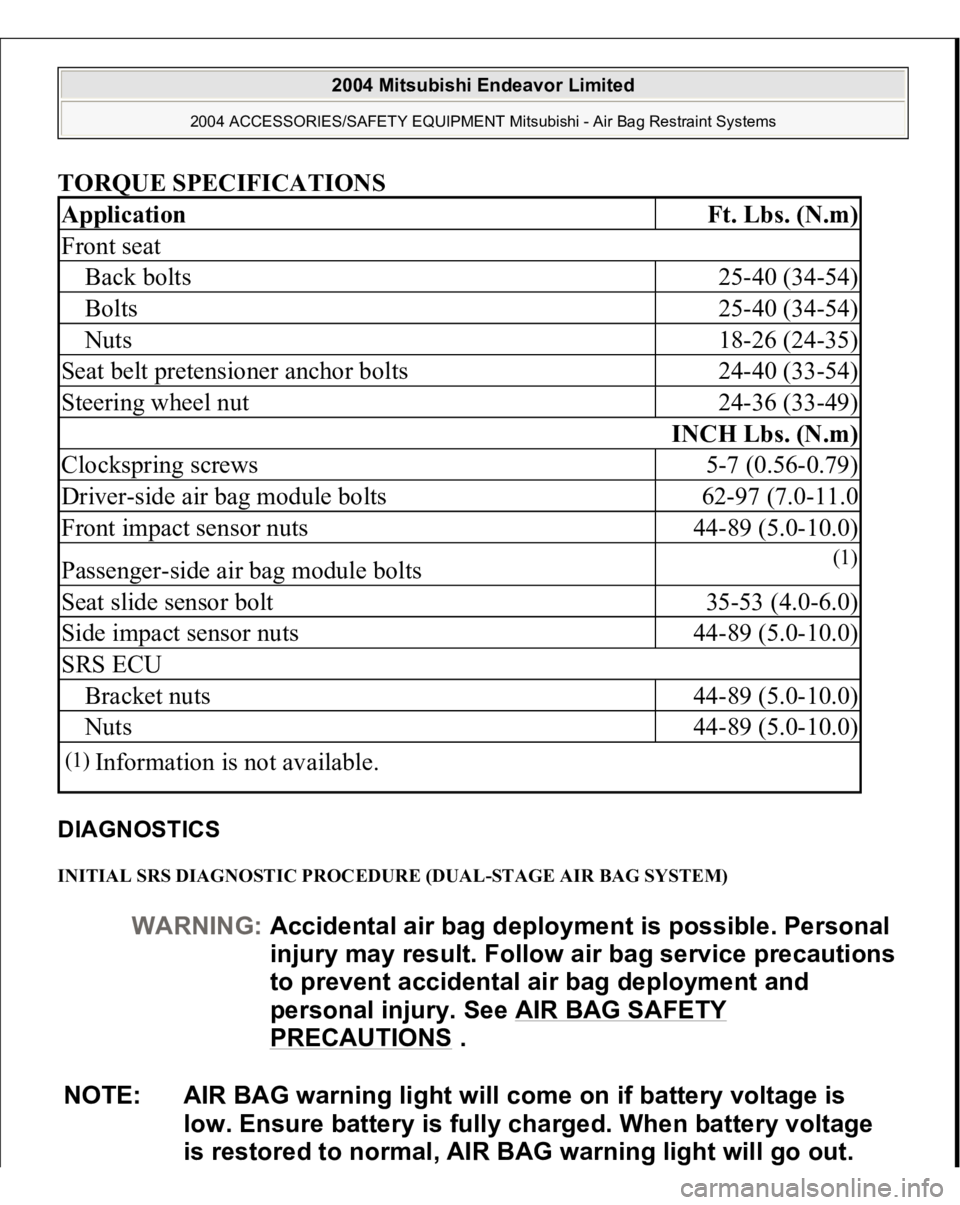
TORQUE SPECIFICATIONS DIAGNOSTICS INITIAL SRS DIAGNOSTIC PROCEDURE (DUAL-STAGE AIR BAG SYSTEM) Application
Ft. Lbs. (N.m)
Front seatBack bolts
25-40 (34-54)
Bolts
25-40 (34-54)
Nuts
18-26 (24-35)
Seat belt pretensioner anchor bolts
24-40 (33-54)
Steering wheel nut
24-36 (33-49)
INCH Lbs. (N.m)
Clockspring screws
5-7 (0.56-0.79)
Driver-side air bag module bolts
62-97 (7.0-11.0
Front impact sensor nuts
44-89 (5.0-10.0)
Passenger-side air bag module bolts
(1)
Seat slide sensor bolt
35-53 (4.0-6.0)
Side impact sensor nuts
44-89 (5.0-10.0)
SRS ECUBracket nuts
44-89 (5.0-10.0)
Nuts
44-89 (5.0-10.0)
(1)
Information is not available.
WARNING:Accidental air bag deployment is possible. Personal
in
jury ma
y result. Follow air ba
g service precautions
to prevent accidental air bag deployment and
personal injury. See AIR BAG SAFETY
PRECAUTIONS
.
NOTE: AIR BAG warning light will come on if battery voltage is
low. Ensure battery is fully charged. When battery voltage
is restored to normal, AIR BAG warning light will go out.
2004 Mitsubishi Endeavor Limited
2004 ACCESSORIES/SAFETY EQUIPMENT Mitsubishi - Air Bag Restraint Systems
Page 673 of 3870
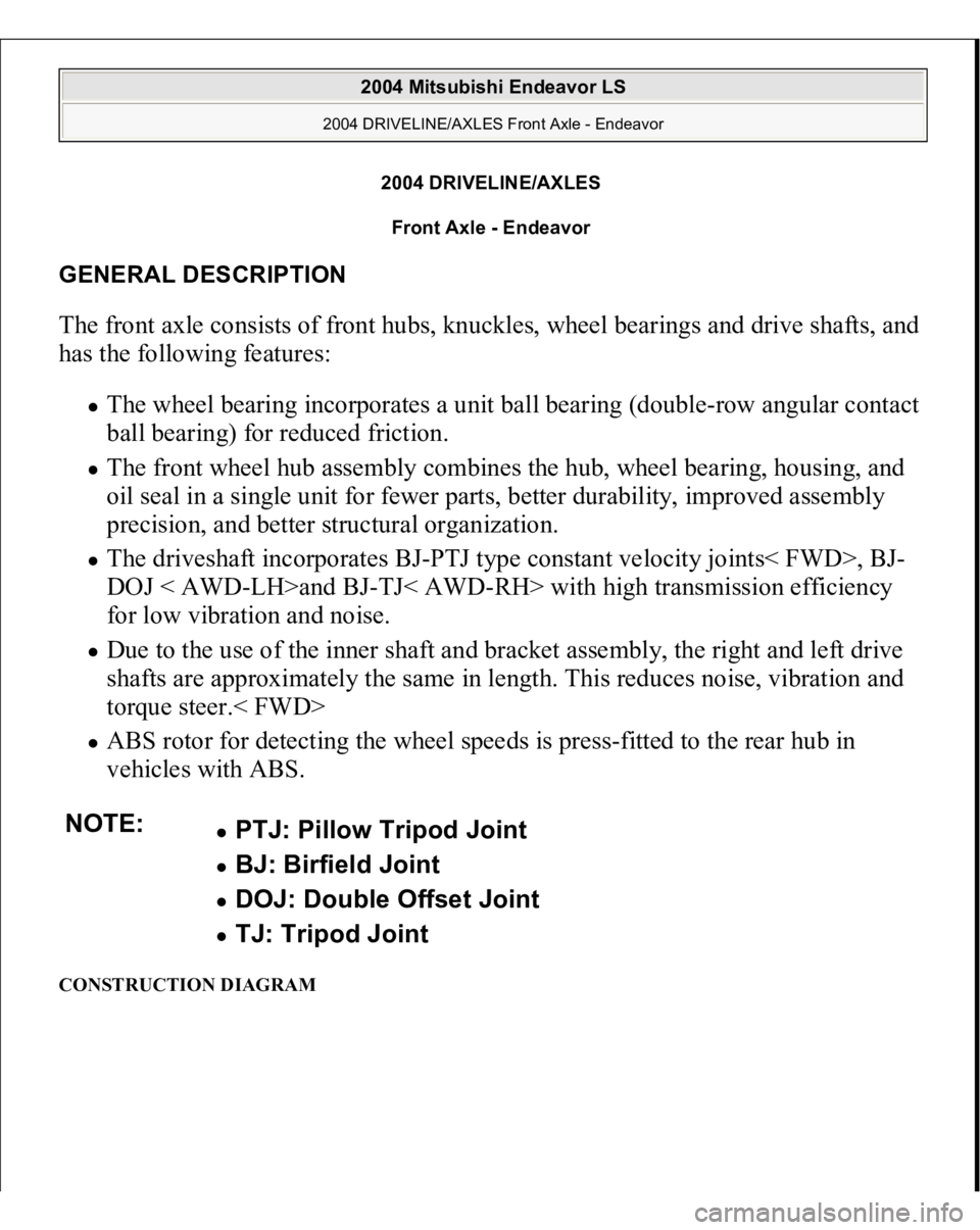
2004 DRIVELINE/AXLES
Front Axle - Endeavor
GENERAL DESCRIPTION The front axle consists of front hubs, knuckles, wheel bearings and drive shafts, and
has the following features:
The wheel bearing incorporates a unit ball bearing (double-row angular contact
ball bearing) for reduced friction. The front wheel hub assembly combines the hub, wheel bearing, housing, and
oil seal in a single unit for fewer parts, better durability, improved assembly
precision, and better structural organization. The driveshaft incorporates BJ-PTJ type constant velocity joints< FWD>, BJ-
DOJ < AWD-LH>and BJ-TJ< AWD-RH> with high transmission efficiency
for low vibration and noise. Due to the use of the inner shaft and bracket assembly, the right and left drive
shafts are approximately the same in length. This reduces noise, vibration and
torque steer.< FWD> ABS rotor for detecting the wheel speeds is press-fitted to the rear hub in
vehicles with ABS.
CONSTRUCTION DIAGRAM NOTE:
PTJ: Pillow Tripod Joint BJ: Birfield Joint DOJ: Double Offset Joint TJ: Tripod Joint
2004 Mitsubishi Endeavor LS
2004 DRIVELINE/AXLES Front Axle - Endeavor
2004 Mitsubishi Endeavor LS
2004 DRIVELINE/AXLES Front Axle - Endeavor
Page 682 of 3870
ON
-VEHICLE SERVIC
E
WHEEL BEARING END PLAY CHECK 1. Remove the caliper assembly and suspend it with a wire.
2. Remove the brake disc from the front hub.
3. Attach a dial gauge as shown in the illustration, and then measure the end play
while moving the hub in the axial direction.
Limit: 0.05 mm (0.002 inch)
4. If end play exceeds the limit, disassemble the front hub assembly and check the
parts.
5. Install the brake disc, caliper assembly and tighten the caliper assembly
mounting bolts to the specified torque 90 +/- 10 N.m (67 +/- 7 ft-lb).
2004 Mitsubishi Endeavor LS
2004 DRIVELINE/AXLES Front Axle - Endeavor
Page 688 of 3870
Fig. 3: Identifying Spacer (MB991000 Or MB990998) & Front Hub Remover & Installer (MB991017)
Courtesy of MITSUBISHI MOTOR SALES OF AMERICA.
Installation Service Points A. When installing the axle shaft, be careful that the splined part of the axle shaft
does not damage the oil seal.
B. Assemble the axle shaft washer as shown. See Fig. 4
. Tighten the axle shaft
nut. See TORQUE SPECIFICATIONS
.
Fig. 4: Removing Washer & Axle Shaft Nut
Courtesy of MITSUBISHI MOTOR SALES OF AMERICA.
CAUTION: DO NOT apply pressure (by vehicle weight) to
wheel bearing before tightening axle shaft nut.
2004 Mitsubishi Endeavor LS
2004 DRIVE AXLES Axle Shafts - Rear - Endeavor
Page 755 of 3870
2. If the disc thickness is less than the limits, replace it with a new one. If
thickness variation exceeds the specification, turn rotor with an on-the-car type
brake lathe ("Accuturn-8750" or equivalent). If the calculated final thickness
after turning the rotor is less than the standard value, replace the disc. BRAKE DISC RUN-OUT CHECK AND CORRECTION 1. Remove the brake assembly, and then hold it with wire.
2. Temporarily install the disc with the hub nut.
3. Place a dial gauge approximately 5 mm (0.2 inch) from the outer
circumference of the brake disc, and measure the run-out of the disc.
Limit:
< Front brake disc>: 0.03 mm (0.0012 inch)
< Rear brake disc>: 0.08 mm (0.0031 inch)
Fig. 37: Identifying M12 Flat Washer
Courtes
y of MITSUBISHI MOTOR SALES OF
A
Grind the brake disc with all wheel nuts dia
gon
equall
y tightened to the specified torque 100
N
lb). When all numbers of wheel nuts are not u
s
the ti
ghtenin
g torque is excessive or not equa
brake disc rotor or drum ma
y be deformed, re
s
judder.
2004 Mitsubishi Endeavor LS
2004 BRAKES Basic Brake System - Endeavor