Page 1096 of 3870

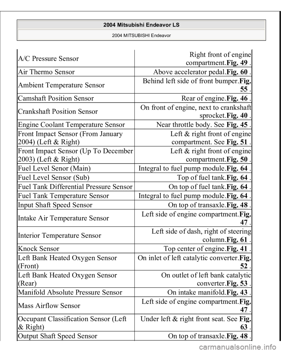
A/C Pressure Sensor
Right front of engine
compartment.Fig. 49
.
Air Thermo Sensor
Above accelerator pedal.Fig. 60
.
Ambient Temperature Sensor
Behind left side of front bumper.Fig.
55 .
Camshaft Position Sensor
Rear of engine.Fig. 46
.
Crankshaft Position Sensor
On front of engine, next to crankshaft
sprocket.Fig. 40
.
Engine Coolant Temperature Sensor
Near throttle body. See Fig. 45
.
Front Impact Sensor (From January
2004) (Left & Right)
Left & right front of engine
compartment. See Fig. 51
.
Front Impact Sensor (Up To December
2003) (Left & Right)
Left & right front of engine
compartment.Fig. 50
.
Fuel Level Senor (Main)
Integral to fuel pump module.Fig. 64
.
Fuel Level Sensor (Sub)
Top of fuel tank.Fig. 64
.
Fuel Tank Differential Pressure Sensor
On top of fuel tank.Fig. 64
.
Fuel Tank Temperature Sensor
Integral to fuel pump module.Fig. 64
.
Input Shaft Speed Sensor
On top of transaxle.Fig. 48
.
Intake Air Temperature Sensor
Left side of engine compartment.Fi
g.
47 .
Interior Temperature Sensor
Left side of dash, right of steering
column.Fig. 61
.
Knock Sensor
Top center of engine.Fig. 41
.
Left Bank Heated Oxygen Sensor
(Front)
On inlet of left catalytic converter.Fi
g.
52 .
Left Bank Heated Oxygen Sensor
(Rear)
On outlet of left bank catalytic
converter.Fig. 53
.
Manifold Absolute Pressure Sensor
On intake manifold.Fig. 43
.
Mass Airflow Sensor
Left side of engine compartment.Fi
g.
47 .
Occupant Classification Sensor (Left
& Right)
Under left & right front seat. See Fi
g.
63 .
Output Shaft Speed Sensor
On top of transaxle.Fig. 48
.
2004 Mitsubishi Endeavor LS
2004 MITSUBISHI Endeavor
Page 1518 of 3870

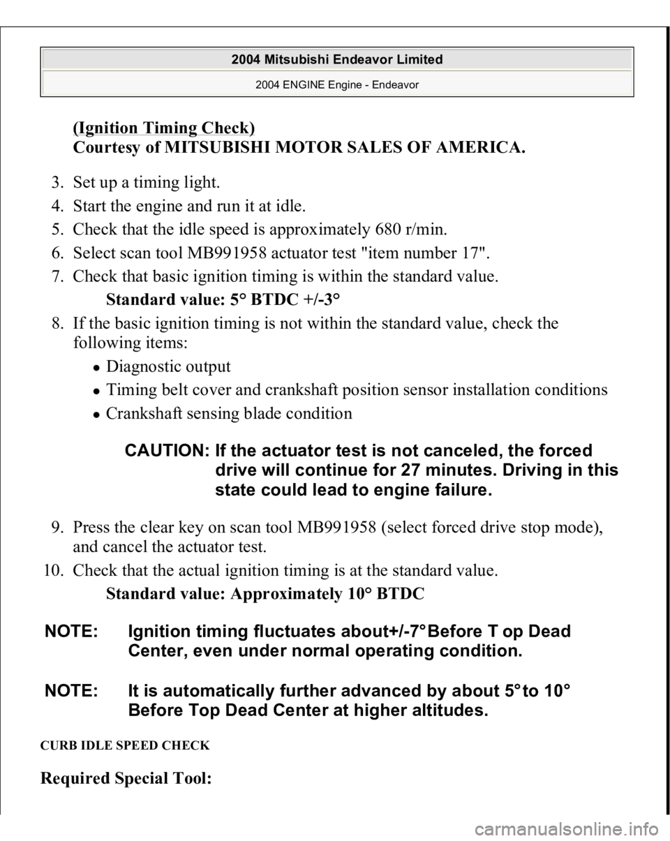
(Ignition Timing Check)
Courtesy of MITSUBISHI MOTOR SALES OF AMERICA.
3. Set up a timing light.
4. Start the engine and run it at idle.
5. Check that the idle speed is approximately 680 r/min.
6. Select scan tool MB991958 actuator test "item number 17".
7. Check that basic ignition timing is within the standard value.
Standard value: 5° BTDC +/-3°
8. If the basic ignition timing is not within the standard value, check the
following items:
Diagnostic output Timing belt cover and crankshaft position sensor installation conditions Crankshaft sensing blade condition
9. Press the clear key on scan tool MB991958 (select forced drive stop mode),
and cancel the actuator test.
10. Check that the actual ignition timing is at the standard value.
Standard value: Approximately 10° BTDC
CURB IDLE SPEED CHECK Required Special Tool:
CAUTION: If the actuator test is not canceled, the forced
drive will continue for 27 minutes. Driving in this
state could lead to engine failure.
NOTE: Ignition timing fluctuates about+/-7° Before T op Dead
Center, even under normal operating condition.
NOTE: It is automatically further advanced by about 5° to 10°
Before Top Dead Center at higher altitudes.
2004 Mitsubishi Endeavor Limited
2004 ENGINE Engine - Endeavor
Page 1525 of 3870
MB991958: Scan Tool (MUT-III Sub Assembly)
MB991824: V.C.I. MB991827: MUT-III USB Cable MB991910: MUT-III Main Harness A
1. Before checks set the vehicle in the following condition:
Engine coolant temperature: 80 - 95°C (176 - 203°F) Lights and all accessories: OFF Transaxle: P range
2. Remove all of the ignition coils and spark plugs.
3. Disconnect the crankshaft position sensor connector.
NOTE: Vehicles for Canada, the headlight, taillight, etc. remain
lit even when the lighting switch is in "OFF" position
but this is no problem for checks.
NOTE: Doing this will prevent the engine control module from
carrying out ignition and fuel injection.
2004 Mitsubishi Endeavor Limited
2004 ENGINE Engine - Endeavor
Page 1526 of 3870
Fig. 21: Disconnecting Crankshaft Position Sensor Connector
Courtesy of MITSUBISHI MOTOR SALES OF AMERICA.
4. Cover the spark plug hole with a shop towel etc., during cranking. After the
engine has been cranked, check for foreign material adhering to the shop towel.
5. Set compression gauge to one of the spark plug holes.
WARNING:Keep your distance from the spark plug hole
when cranking. Oil, fuel, etc., may spray out
from the spark plug hole and may cause serious
injury.
2004 Mitsubishi Endeavor Limited
2004 ENGINE Engine - Endeavor
Page 1528 of 3870
malfunction is a worn or damaged piston ring and/or cylinder inner
surface.
2. If the compression does not rise after oil is added, the cause is a burnt or
defective valve seat, or pressure is leaking from the gasket.
9. Connect the crankshaft position sensor connector.
10. Install the spark plugs and ignition coils.
11. Use the scan tool MB991958 to erase the diagnostic trouble codes.
NOTE: This will erase the diagnostic trouble code resulting from
the crankshaft position sensor connector being
disconnected.
2004 Mitsubishi Endeavor Limited
2004 ENGINE Engine - Endeavor
Page 2683 of 3870

2004 ENGINE
Ignition System - Endeavor
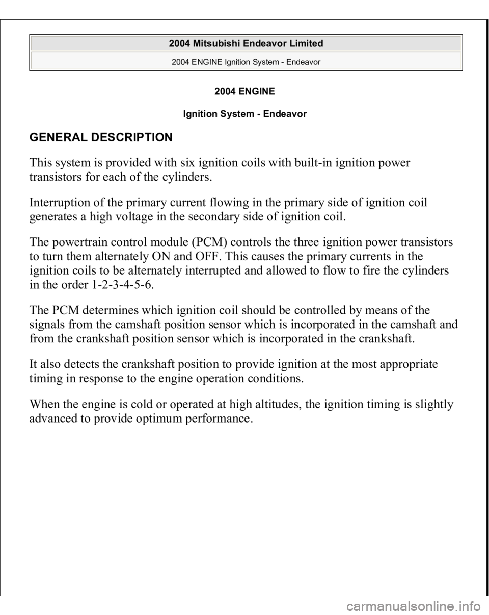
GENERAL DESCRIPTION This system is provided with six ignition coils with built-in ignition power
transistors for each of the cylinders.
Interruption of the primary current flowing in the primary side of ignition coil
generates a high voltage in the secondary side of ignition coil.
The powertrain control module (PCM) controls the three ignition power transistors
to turn them alternately ON and OFF. This causes the primary currents in the
ignition coils to be alternately interrupted and allowed to flow to fire the cylinders
in the order 1-2-3-4-5-6.
The PCM determines which ignition coil should be controlled by means of the
signals from the camshaft position sensor which is incorporated in the camshaft and
from the crankshaft position sensor which is incorporated in the crankshaft.
It also detects the crankshaft position to provide ignition at the most appropriate
timing in response to the engine operation conditions.
When the engine is cold or operated at high altitudes, the ignition timing is slightly
advanced to
provide o
ptimum
performance.
2004 Mitsubishi Endeavor Limited 2004 ENGINE Ignition System - Endeavor
2004 Mitsubishi Endeavor Limited 2004 ENGINE Ignition System - Endeavor
Page 2689 of 3870
Fig. 7: Locating Iridium Tip
Courtesy of MITSUBISHI MOTOR SALES OF AMERICA.
CAMSHAFT POSITION SENSOR CHECK Refer to DTC P0340: CAMSHAFT POSITION SENSOR CIRCUIT
.
CRANKSHAFT POSITION SENSOR CHECK Refer to DTC P0335: CRANKSHAFT POSITION SENSOR CIRCUIT
.
2004 Mitsubishi Endeavor Limited 2004 ENGINE Ignition System - Endeavor
Page 2691 of 3870
Fig. 9: Removing And Installing Camshaft Position Sensor
Courtesy of MITSUBISHI MOTOR SALES OF AMERICA.
CRANKSHAFT POSITION SENSOR REMOVAL AND INSTALLATION Pre-removal and Post-installation Operation
Timin
g Belt Lower Cover Removal and Installation
(Refer to TIMING BELT
).
2004 Mitsubishi Endeavor Limited 2004 ENGINE Ignition System - Endeavor